Page 1890 of 2493
Trouble Diagnoses: ªAIR BAGº Warning Lamp
Does Not Turn On
=NJRS0051DIAGNOSTIC PROCEDURE 10NJRS0051S01
1 CHECK ªMETERº FUSE
Is meter fuse OK?
SRS836
OK or NG
OK©GO TO 3.
NG©GO TO 2.
2 CHECK ªMETERº FUSE AGAIN
Replace meter fuse and turn ignition switch ON.
Is meter fuse blown again?
Ye s©Repair main harness.
No©INSPECTION END
3 CHECK ªAIR BAGº WARNING LAMP LED
Is ªAIR BAGº warning lamp LED OK?
OK or NG
OK©GO TO 4.
NG©Replace ªAIR BAGº warning lamp LED.
4 CHECK HARNESS CONNECTION BETWEEN DIAGNOSIS SENSOR UNIT AND ªAIR BAGº WARNING
LAMP
Disconnect diagnosis sensor unit connector and turn ignition switch ªONº.
+Does ªAIR BAGº warning lamp turn on?
YesorNo
Ye s©Replace diagnosis sensor unit.
No©Check the ground circuit of ªAIR BAGº warning lamp.
SUPPLEMENTAL RESTRAINT SYSTEM (SRS)
Trouble Diagnoses: ªAIR BAGº Warning Lamp Does Not Turn On
RS-70
Page 1950 of 2493
Removal and InstallationNJBT0018+When removing or installing the seat trim, carefully handle it to keep dirt out and avoid damage.
HFor Wiring Diagram, refer to EL-163, ªWiring Diagram Ð HEATED SEAT к.
CAUTION:
+Before removing the front seat, turn the ignition switch off, disconnect both battery cables and wait
at least 3 minutes.
+Do not drop, tilt, or bump the side air bag module installed in the seat. Always handle it with care.
+Disconnect the side air bag harness connector and heated seat harness connector from under the
seat before removing the seat.
+Disconnect the side air bag harness connector before removing the seat back. Refer to RS-33,
ªFront Side Air Bag Moduleº for details.
FRONT SEAT
Removal and Installation
BT-56
Page 1986 of 2493
CSV613 Variable Displacement Compressor
GENERAL INFORMATIONNJHA02061. The CSV613 compressor differs from previous units. The vent temperatures of the CSV613 compressor
do not drop too far below 5ÉC (41ÉF) when:
+evaporator intake air temperature is less than 20ÉC (68ÉF)
+engine is running at speeds less than 1,500 rpm.
This is because the CSV613 compressor provides a means of ªcapacityº control.
2. The CSV613 compressor provides refrigerant control under varying conditions. During cold winters, it may
not produce high refrigerant pressure discharge (compared to previous units) when used with air condi-
tioning systems.
3. A ªclankingº sound may occasionally be heard during refrigerant charge. The sound indicates that the tilt
angle of the swash plate has changed and is not a problem.
4. For air conditioning systems with the CSV613 compressor, the clutch remains engaged unless: the sys-
tem main switch, fan switch or ignition switch is turned OFF. When ambient (outside) temperatures are
low or when the amount of refrigerant is insufficient, the clutch is disengaged to protect the compressor.
5. A constant range of suction pressure is maintained when engine speed is greater than a certain value. It
normally ranges from 147 to 177 kPa (1.47 to 1.77 bar, 1.5 to 1.8 kg/cm
2, 21 to 26 psi) under varying con-
ditions.
In previous compressors, however, suction pressure was reduced with increases in engine speed.
DESCRIPTION
CSV613 Variable Displacement Compressor
HA-14
Page 2023 of 2493
RHA796H
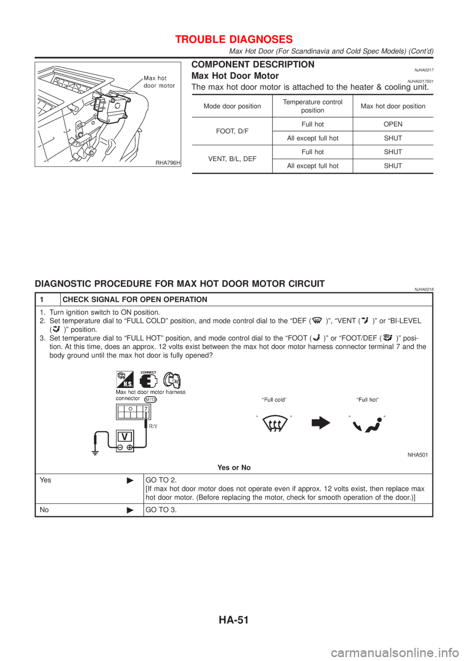
COMPONENT DESCRIPTIONNJHA0217Max Hot Door MotorNJHA0217S01The max hot door motor is attached to the heater & cooling unit.
Mode door positionTemperature control
positionMax hot door position
FOOT, D/FFull hot OPEN
All except full hot SHUT
VENT, B/L, DEFFull hot SHUT
All except full hot SHUT
DIAGNOSTIC PROCEDURE FOR MAX HOT DOOR MOTOR CIRCUITNJHA0218
1 CHECK SIGNAL FOR OPEN OPERATION
1. Turn ignition switch to ON position.
2. Set temperature dial to ªFULL COLDº position, and mode control dial to the ªDEF (
)º, ªVENT ()º or ªBI-LEVEL
(
)º position.
3. Set temperature dial to ªFULL HOTº position, and mode control dial to the ªFOOT (
)º or ªFOOT/DEF ()º posi-
tion. At this time, does an approx. 12 volts exist between the max hot door motor harness connector terminal 7 and the
body ground until the max hot door is fully opened?
NHA501
YesorNo
Ye s©GO TO 2.
[If max hot door motor does not operate even if approx. 12 volts exist, then replace max
hot door motor. (Before replacing the motor, check for smooth operation of the door.)]
No©GO TO 3.
TROUBLE DIAGNOSES
Max Hot Door (For Scandinavia and Cold Spec Models) (Cont'd)
HA-51
Page 2024 of 2493
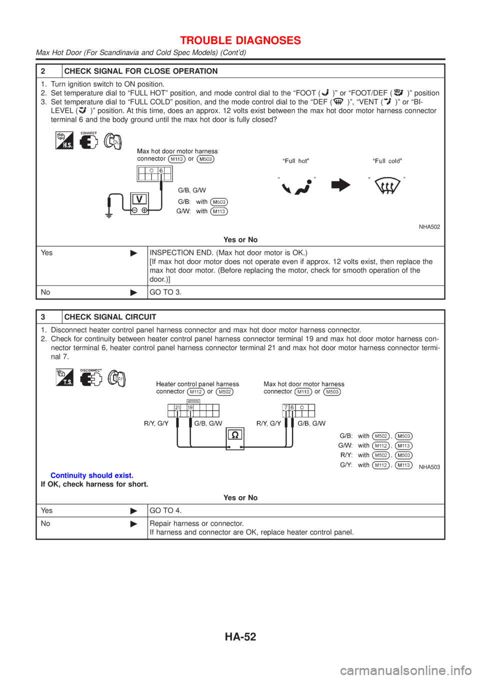
2 CHECK SIGNAL FOR CLOSE OPERATION
1. Turn ignition switch to ON position.
2. Set temperature dial to ªFULL HOTº position, and mode control dial to the ªFOOT (
)º or ªFOOT/DEF ()º position
3. Set temperature dial to ªFULL COLDº position, and the mode control dial to the ªDEF (
)º, ªVENT ()º or ªBI-
LEVEL (
)º position. At this time, does an approx. 12 volts exist between the max hot door motor harness connector
terminal 6 and the body ground until the max hot door is fully closed?
NHA502
YesorNo
Ye s©INSPECTION END. (Max hot door motor is OK.)
[If max hot door motor does not operate even if approx. 12 volts exist, then replace the
max hot door motor. (Before replacing the motor, check for smooth operation of the
door.)]
No©GO TO 3.
3 CHECK SIGNAL CIRCUIT
1. Disconnect heater control panel harness connector and max hot door motor harness connector.
2. Check for continuity between heater control panel harness connector terminal 19 and max hot door motor harness con-
nector terminal 6, heater control panel harness connector terminal 21 and max hot door motor harness connector termi-
nal 7.
NHA503
Continuity should exist.
If OK, check harness for short.
YesorNo
Ye s©GO TO 4.
No©Repair harness or connector.
If harness and connector are OK, replace heater control panel.
TROUBLE DIAGNOSES
Max Hot Door (For Scandinavia and Cold Spec Models) (Cont'd)
HA-52
Page 2025 of 2493
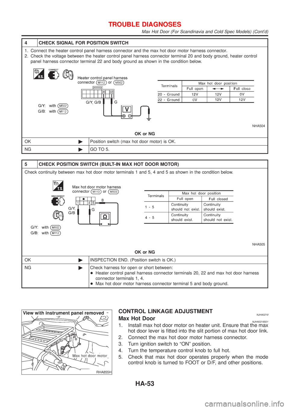
4 CHECK SIGNAL FOR POSITION SWITCH
1. Connect the heater control panel harness connector and the max hot door motor harness connector.
2. Check the voltage between the heater control panel harness connector terminal 20 and body ground, heater control
panel harness connector terminal 22 and body ground as shown in the condition below.
NHA504
OK or NG
OK©Position switch (max hot door motor) is OK.
NG©GO TO 5.
5 CHECK POSITION SWITCH (BUILT-IN MAX HOT DOOR MOTOR)
Check continuity between max hot door motor terminals 1 and 5, 4 and 5 as shown in the condition below.
NHA505
OK or NG
OK©INSPECTION END. (Position switch is OK.)
NG©Check harness for open or short between:
+Heater control panel harness connector terminals 20, 22 and max hot door harness
connector terminals 1, 4.
+Max hot door motor harness connector terminal 5 and body ground.
RHA855H
CONTROL LINKAGE ADJUSTMENTNJHA0219Max Hot DoorNJHA0219S011. Install max hot door motor on heater unit. Ensure that the max
hot door lever is fitted into the slit portion of max hot door link.
2. Connect the max hot door motor harness connector.
3. Turn ignition switch to ªONº position.
4. Turn the temperature control knob to full hot.
5. Check that max hot door operates properly when the mode
control knob is turned to FOOT or D/F, and other positions.
TROUBLE DIAGNOSES
Max Hot Door (For Scandinavia and Cold Spec Models) (Cont'd)
HA-53
Page 2075 of 2493
CompressorNJHA0174
ModelCALSONIC make CSV613
TypeSwash plate (Variable displacement)
Displacement cm
3(cu in)/rev.6.0 - 125 (0.37 - 7.63)
Direction of rotationClockwise (viewed from drive end)
Drive beltQG engine model: Poly V
YD engine model: Type A
LubricantNJHA0175
ModelCALSONIC make CSV613
NameNissan A/C System Oil Type S
Part numberKLH00-PAGS0
Capacity
m!(Imp fl oz)Total in system 180 (6.3) - 200 (7.0)
Compressor (Service part) charging amount 180 (6.3) - 200 (7.0)
RefrigerantNJHA0176
TypeHFC-134a (R-134a)
Capacity kg (lb)0.45 - 0.55 (0.99 - 1.21)
Engine Idling Speed (When A/C is On)NJHA0177+Refer to EC-489 (QG), EC-702 (YD), ªIdle Speed and Ignition Timingº.
Belt TensionNJHA0178+Refer to EM-15 (QG), EM-84 (YD), ªChecking Drive Beltsº.
SERVICE DATA AND SPECIFICATIONS (SDS)
Compressor
HA-103
Page 2089 of 2493
System DescriptionNJSC0004M/T MODELSNJSC0004S01Power is supplied at all times
+through 40A fusible link (letterB, located in the fuse and fusible link box)
+to ignition switch terminal 1.
With the ignition switch in START position, power is supplied
+from ignition switch terminal 5
+to starter motor harness connector terminal 1.
The starter motor plunger closes and provides a closed circuit between the battery and starter motor. The
starter motor is grounded to the engine block. With power and ground supplied, cranking occurs and the engine
starts.
A/T MODELSNJSC0004S02Power is supplied at all times
+through 40A fusible link (letterB, located in the fuse and fusible link box)
+to ignition switch terminal 1.
With the ignition switch in the START position, power is supplied
+from ignition switch terminal 5
+to park/neutral position relay terminal 5.
With the ignition switch ON or START position, power is supplied
+through 10A fuse [No. 20, located in the fuse block (J/B)]
+to park/neutral position (PNP) relay terminal 1.
With the selector lever in the P or N position, ground is supplied
+to park/neutral position relay terminal 2 through the park/neutral position switch
+from body grounds, F9 and F10.
Then park/neutral position relay is energized and power is supplied
+from park/neutral position relay terminal 3
+to starter motor harness connector terminal 1.
The starter motor plunger closes and provides a closed circuit between the battery and starter motor. The
starter motor is grounded to the engine block. With power and ground supplied, cranking occurs and the engine
starts.
STARTING SYSTEM
System Description
SC-13