Page 2224 of 2493

NEL796
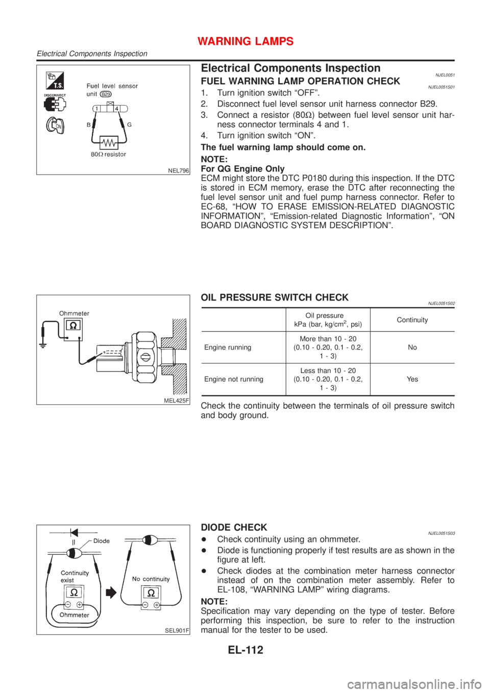
Electrical Components InspectionNJEL0051FUEL WARNING LAMP OPERATION CHECKNJEL0051S011. Turn ignition switch ªOFFº.
2. Disconnect fuel level sensor unit harness connector B29.
3. Connect a resistor (80W) between fuel level sensor unit har-
ness connector terminals 4 and 1.
4. Turn ignition switch ªONº.
The fuel warning lamp should come on.
NOTE:
For QG Engine Only
ECM might store the DTC P0180 during this inspection. If the DTC
is stored in ECM memory, erase the DTC after reconnecting the
fuel level sensor unit and fuel pump harness connector. Refer to
EC-68, ªHOW TO ERASE EMISSION-RELATED DIAGNOSTIC
INFORMATIONº, ªEmission-related Diagnostic Informationº, ªON
BOARD DIAGNOSTIC SYSTEM DESCRIPTIONº.
MEL425F
OIL PRESSURE SWITCH CHECKNJEL0051S02
Oil pressure
kPa (bar, kg/cm2, psi)Continuity
Engine runningMore than 10 - 20
(0.10 - 0.20, 0.1 - 0.2,
1-3)No
Engine not runningLess than 10 - 20
(0.10 - 0.20, 0.1 - 0.2,
1-3)Ye s
Check the continuity between the terminals of oil pressure switch
and body ground.
SEL901F
DIODE CHECKNJEL0051S03+Check continuity using an ohmmeter.
+Diode is functioning properly if test results are as shown in the
figure at left.
+Check diodes at the combination meter harness connector
instead of on the combination meter assembly. Refer to
EL-108, ªWARNING LAMPº wiring diagrams.
NOTE:
Specification may vary depending on the type of tester. Before
performing this inspection, be sure to refer to the instruction
manual for the tester to be used.
WARNING LAMPS
Electrical Components Inspection
EL-112
Page 2225 of 2493

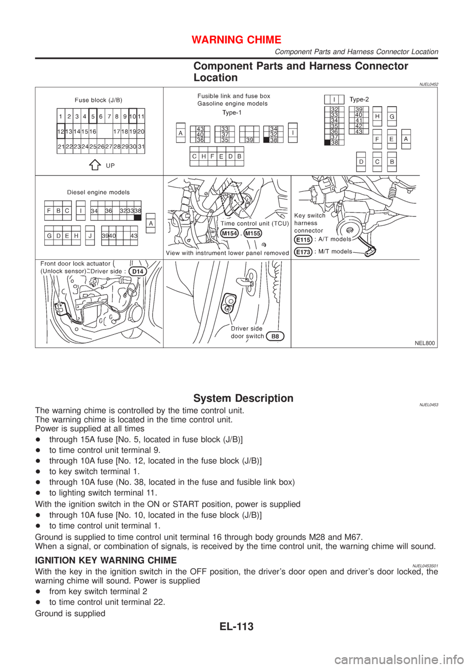
Component Parts and Harness Connector
Location
NJEL0452
NEL800
System DescriptionNJEL0453The warning chime is controlled by the time control unit.
The warning chime is located in the time control unit.
Power is supplied at all times
+through 15A fuse [No. 5, located in fuse block (J/B)]
+to time control unit terminal 9.
+through 10A fuse [No. 12, located in the fuse block (J/B)]
+to key switch terminal 1.
+through 10A fuse (No. 38, located in the fuse and fusible link box)
+to lighting switch terminal 11.
With the ignition switch in the ON or START position, power is supplied
+through 10A fuse [No. 10, located in the fuse block (J/B)]
+to time control unit terminal 1.
Ground is supplied to time control unit terminal 16 through body grounds M28 and M67.
When a signal, or combination of signals, is received by the time control unit, the warning chime will sound.
IGNITION KEY WARNING CHIMENJEL0453S01With the key in the ignition switch in the OFF position, the driver's door open and driver's door locked, the
warning chime will sound. Power is supplied
+from key switch terminal 2
+to time control unit terminal 22.
Ground is supplied
WARNING CHIME
Component Parts and Harness Connector Location
EL-113
Page 2226 of 2493
+from body grounds B9, B21 and D96 (Hatchback) or B308 (Sedan)
+through front door switch (driver side) terminal 3 and 2
+to time control unit terminal 6, and
Ground is interrupted,
+from body grounds M28 and M67
+to time control unit terminal 35
LIGHT WARNING CHIMENJEL0453S02With ignition switch OFF, driver's door open, and lighting switch in 1ST or 2ND position, warning chime will
sound. Power is supplied.
+from lighting switch terminal 12
+to time control unit terminal 10
Ground is supplied
+from front door switch (driver side) terminal 2
+to time control unit terminal 6.
Front door switch (driver side) terminal 3 is grounded through body grounds B9, B21 and D96 (Hatchback) or
B308 (Sedan).
WARNING CHIME
System Description (Cont'd)
EL-114
Page 2229 of 2493
Trouble DiagnosesNJEL0455SYMPTOM CHARTNJEL0455S01
REFERENCE PAGE (EL- ) 117 118 119 120 121
SYMPTOM
POWER SUPPLY AND
GROUND CIRCUIT CHECK
DIAGNOSTIC PROCEDURE 1
(LIGHTING SWITCH INPUT
SIGNAL CHECK)
DIAGNOSTIC PROCEDURE 2
(KEY SWITCH INSERT
SIGNAL CHECK)
DIAGNOSTIC PROCEDURE 3
(DOOR UNLOCK SENSOR CHECK)
DIAGNOSTIC PROCEDURE 4
Light warning chime does not acti-
vate.XX X
Ignition key warning chime does not
activate.XXXX
All warning chimes do not activate. XX
POWER SUPPLY AND GROUND CIRCUIT CHECKNJEL0455S02Power Supply Circuit CheckNJEL0455S0201
SEL447X
Ground Circuit CheckNJEL0455S0202
SEL448X
WARNING CHIME
Trouble Diagnoses
EL-117
Page 2233 of 2493
DIAGNOSTIC PROCEDURE 4NJEL0455S06
1 CHECK IGNITION ON SIGNAL
Check voltage between time control unit terminal 1 or 9 and ground.
SEL447X
OK or NG
OK©GO TO 2.
NG©Check the following.
+10A fuse [No. 10, located in fuse block (J/B)]
+15A fuse [No. 5, located in the fuse block (J/B)]
+Harness for open or short between time control unit and fuse
2 CHECK DOOR SWITCH INPUT SIGNAL
Check voltage between time control unit terminal 6 and ground.
SEL430X
OK or NG
OK©System is OK.
NG©Check voltage between time control unit terminal 6 and body ground with disconnecting
front door switch (driver side).
If approx. 5V is supplied, GO TO 3.
If approx. 5V is not supplied, replace time control unit.
WARNING CHIME
Trouble Diagnoses (Cont'd)
EL-121
Page 2235 of 2493

System DescriptionNJEL0456WIPER OPERATIONNJEL0456S01The wiper switch is controlled by a lever built into the combination switch.
There are three wiper switch positions:
+LO speed
+HI speed
+INT (Intermittent)
With the ignition switch in the ON or START position, power is supplied
+through 20A fuse [No. 25, located in the fuse block (J/B)]
+to front wiper motor terminal 5 and front wiper relay terminal 2.
Low and High Speed Wiper OperationNJEL0456S0101Ground is supplied to wiper and washer switch terminal 17 through body grounds E30 and E73.
When the wiper switch is placed in the LO position, ground is supplied
+through terminal 14 of the front wiper and washer switch
+to front wiper motor terminal 2.
With power and ground supplied, the wiper motor operates at low speed.
When the wiper switch is placed in the HI position, ground is supplied
+through terminal 16 of the front wiper and washer switch
+to wiper motor terminal 1.
With power and ground supplied, the wiper motor operates at high speed.
Auto Stop OperationNJEL0456S0102With wiper switch turned OFF, wiper motor will continue to operate until wiper arms reach windshield base.
When wiper arms are not located at base of windshield with wiper switch OFF, ground is provided
+from terminal 14 of the front wiper and washer switch
+to front wiper motor terminal 2, in order to continue wiper motor operation at low speed.
Ground is also supplied
+through terminal 13 of the front wiper and washer switch
+to front wiper relay terminal 3
+through terminal 4 of the front wiper relay.
+to front wiper motor terminal 3
+through terminal 4 of front wiper motor
+through body grounds E30 and E73.
When wiper arms reach base of windshield, front wiper motor terminals 3 and 5 are connected instead of ter-
minals 3 and 4. Wiper motor will then stop wiper arms at the STOP position.
Intermittent OperationNJEL0456S0103The front wiper motor operates the wiper arms one time at low speed at a set interval of approximately 1 to
13 seconds. This feature is controlled by the wiper amplifier (INT SW) combined with front wiper switch.
When the wiper switch is placed in the INT position, ground is supplied to wiper amplifier (WIPER SW INT)
and (ACC).
The desired interval time is input to wiper amplifier (INT VR) from wiper volume switch combined with front
wiper and washer switch.
Then intermittent ground is supplied
+from body grounds E30 and E73
+through terminal 5 of front wiper relay,
+through terminal 3 of front wiper relay,
+through terminal 13 of front wiper switch and,
+through terminal 14 of front wiper switch
+to terminal 2 of front wiper motor.
The desired interval time is input
+to front wiper relay terminal 1
+from terminal 20 of front wiper switch
FRONT WIPER AND WASHER
System Description
EL-123
Page 2236 of 2493
WASHER OPERATIONNJEL0456S02With the ignition switch in the ON or START position, power is supplied
+through 10A fuse [No. 27, located in the fuse block (J/B)]
+to front wiper switch terminal 5.
When the lever is pulled to the WASH/F position, ground is supplied
+from body grounds E30 and E73,
+through terminal 4 of the front wiper switch, and
+through terminal 18 of the frotn wiper switch
+to front washer motor terminal 2.
With power and ground supplied, the washer motor operates.
When the lever is pulled to the WASH position for one second or more, the wiper motor operates at low speed
for approximately 3 seconds to clean windshield. This feature is controlled by the wiper amplifier in the same
manner as the intermittent operation.
FRONT WIPER AND WASHER
System Description (Cont'd)
EL-124
Page 2250 of 2493

System Description=NJEL0463The rear window defogger system is controlled by the time control unit. The rear window defogger operates
only for approximately 15 minutes.
Power is supplied at all times
+through 20A fuse [No. 7, located in the fuse block (J/B)]
+to rear window defogger relay terminal 5 (B7 relay models) or 3 (B6 relay models)
+through 10A fuse [No. 13, located in the fuse block (J/B)]
+to rear window defogger relay terminal 6 (B6 relay models).
+through 15A fuse [No. 5, located in the fuse block (J/B)]
+to time control unit terminal 9.
With the ignition switch in the ON or START position, power is supplied
+through 10A fuse [No. 10, located in the fuse block (J/B)]
+to the rear window defogger relay terminal 1 and
+to time control unit terminal 1.
Ground is supplied to terminal 5 of the rear window defogger switch through body grounds M28 and M67.
When the rear defogger switch is turned ON, ground is supplied
+through terminal 3 of the rear defogger switch
+to time control unit terminal 3.
Terminal 13 of time control unit then supplies ground to the rear window defogger relay terminal 2.
With power and ground supplied, the rear window defogger relay is energized.
Power is supplied
+through terminals 5 and 7 of the rear window defogger relay (B6 relay models) or
+through terminal 3 of the rear window defogger relay (B7 relay models)
+to the rear window defogger and door mirror defogger.
The rear window defogger has an independent ground.
With power and ground supplied, the rear window defogger filaments heat and defog the rear window.
When the system is activated, the rear window defogger indicator illuminates in the rear window defogger
switch.
REAR WINDOW DEFOGGER
System Description
EL-138