2001 NISSAN ALMERA N16 Tail
[x] Cancel search: TailPage 1852 of 2493
SRS824
Front Passenger Air Bag Module
REMOVALNJRS0018CAUTION:
+Before servicing SRS, turn the ignition switch off, discon-
nect both battery cables and wait for at least 3 minutes.
+Always work from the side of or under front passenger air
bag module.
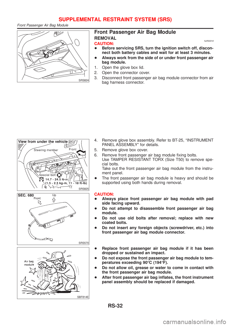
1. Open the glove box lid.
2. Open the connector cover.
3. Disconnect front passenger air bag module connector from air
bag harness connector.
SRS825
4. Remove glove box assembly. Refer to BT-25, ªINSTRUMENT
PANEL ASSEMBLYº for details.
5. Remove glove box cover.
6. Remove front passenger air bag module fixing bolts.
Use TAMPER RESISTANT TORX (Size T50) to remove spe-
cial bolts.
Take out the front passenger air bag module from the instru-
ment panel.
+The front passenger air bag module is heavy and should be
supported using both hands during removal.
SRS570
CAUTION:
+Always place front passenger air bag module with pad
side facing upward.
+Do not attempt to disassemble front passenger air bag
module.
+Do not use old bolts after removal; replace with new
coated bolts.
+Do not insert any foreign objects (screwdriver, etc.) into
front passenger air bag module connector.
SBF814E
+Replace front passenger air bag module if it has been
dropped or sustained an impact.
+Do not expose the front passenger air bag module to tem-
peratures exceeding 90ÉC (194ÉF).
+Do not allow oil, grease or water to come in contact with
the front passenger air bag module.
+After front passenger air bag inflates, the front instrument
panel assembly should be replaced if damaged.
SUPPLEMENTAL RESTRAINT SYSTEM (SRS)
Front Passenger Air Bag Module
RS-32
Page 1891 of 2493
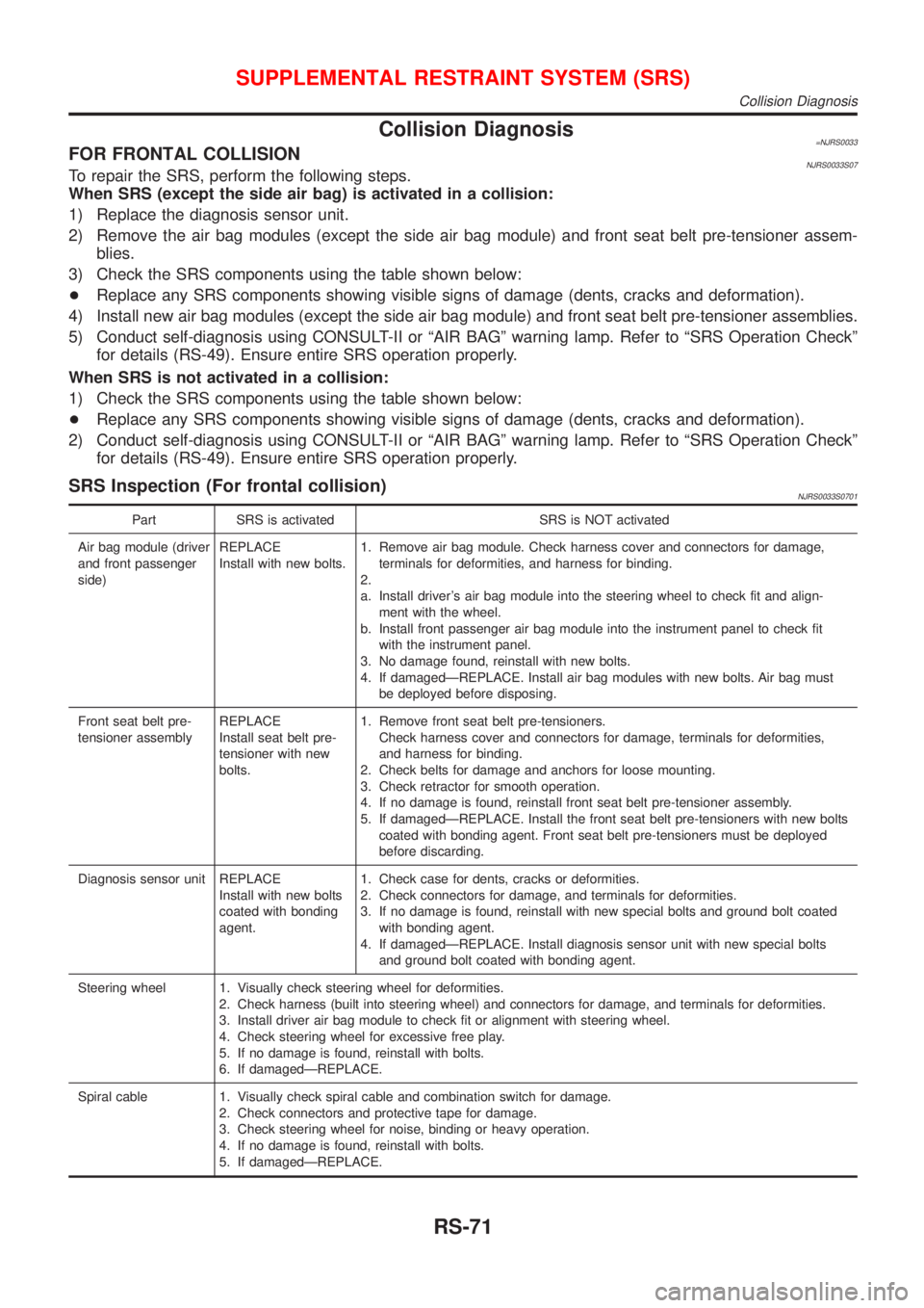
Collision Diagnosis=NJRS0033FOR FRONTAL COLLISIONNJRS0033S07To repair the SRS, perform the following steps.
When SRS (except the side air bag) is activated in a collision:
1) Replace the diagnosis sensor unit.
2) Remove the air bag modules (except the side air bag module) and front seat belt pre-tensioner assem-
blies.
3) Check the SRS components using the table shown below:
+Replace any SRS components showing visible signs of damage (dents, cracks and deformation).
4) Install new air bag modules (except the side air bag module) and front seat belt pre-tensioner assemblies.
5) Conduct self-diagnosis using CONSULT-II or ªAIR BAGº warning lamp. Refer to ªSRS Operation Checkº
for details (RS-49). Ensure entire SRS operation properly.
When SRS is not activated in a collision:
1) Check the SRS components using the table shown below:
+Replace any SRS components showing visible signs of damage (dents, cracks and deformation).
2) Conduct self-diagnosis using CONSULT-II or ªAIR BAGº warning lamp. Refer to ªSRS Operation Checkº
for details (RS-49). Ensure entire SRS operation properly.
SRS Inspection (For frontal collision)NJRS0033S0701
Part SRS is activated SRS is NOT activated
Air bag module (driver
and front passenger
side)REPLACE
Install with new bolts.1. Remove air bag module. Check harness cover and connectors for damage,
terminals for deformities, and harness for binding.
2.
a. Install driver's air bag module into the steering wheel to check fit and align-
ment with the wheel.
b. Install front passenger air bag module into the instrument panel to check fit
with the instrument panel.
3. No damage found, reinstall with new bolts.
4. If damagedÐREPLACE. Install air bag modules with new bolts. Air bag must
be deployed before disposing.
Front seat belt pre-
tensioner assemblyREPLACE
Install seat belt pre-
tensioner with new
bolts.1. Remove front seat belt pre-tensioners.
Check harness cover and connectors for damage, terminals for deformities,
and harness for binding.
2. Check belts for damage and anchors for loose mounting.
3. Check retractor for smooth operation.
4. If no damage is found, reinstall front seat belt pre-tensioner assembly.
5. If damagedÐREPLACE. Install the front seat belt pre-tensioners with new bolts
coated with bonding agent. Front seat belt pre-tensioners must be deployed
before discarding.
Diagnosis sensor unit REPLACE
Install with new bolts
coated with bonding
agent.1. Check case for dents, cracks or deformities.
2. Check connectors for damage, and terminals for deformities.
3. If no damage is found, reinstall with new special bolts and ground bolt coated
with bonding agent.
4. If damagedÐREPLACE. Install diagnosis sensor unit with new special bolts
and ground bolt coated with bonding agent.
Steering wheel 1. Visually check steering wheel for deformities.
2. Check harness (built into steering wheel) and connectors for damage, and terminals for deformities.
3. Install driver air bag module to check fit or alignment with steering wheel.
4. Check steering wheel for excessive free play.
5. If no damage is found, reinstall with bolts.
6. If damagedÐREPLACE.
Spiral cable 1. Visually check spiral cable and combination switch for damage.
2. Check connectors and protective tape for damage.
3. Check steering wheel for noise, binding or heavy operation.
4. If no damage is found, reinstall with bolts.
5. If damagedÐREPLACE.
SUPPLEMENTAL RESTRAINT SYSTEM (SRS)
Collision Diagnosis
RS-71
Page 1893 of 2493
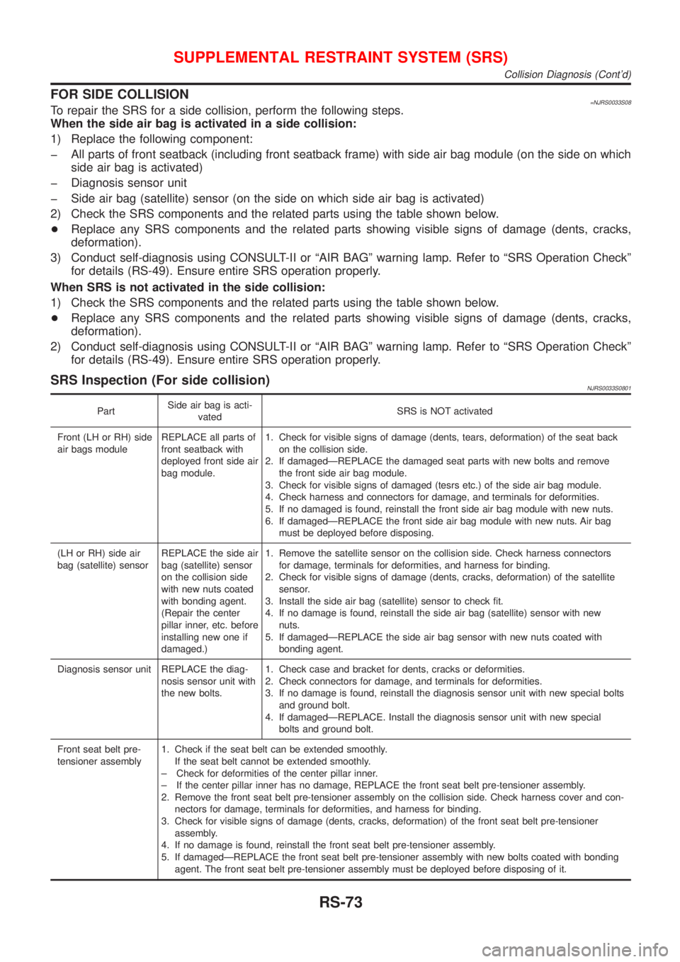
FOR SIDE COLLISION=NJRS0033S08To repair the SRS for a side collision, perform the following steps.
When the side air bag is activated in a side collision:
1) Replace the following component:
þ All parts of front seatback (including front seatback frame) with side air bag module (on the side on which
side air bag is activated)
þ Diagnosis sensor unit
þ Side air bag (satellite) sensor (on the side on which side air bag is activated)
2) Check the SRS components and the related parts using the table shown below.
+Replace any SRS components and the related parts showing visible signs of damage (dents, cracks,
deformation).
3) Conduct self-diagnosis using CONSULT-II or ªAIR BAGº warning lamp. Refer to ªSRS Operation Checkº
for details (RS-49). Ensure entire SRS operation properly.
When SRS is not activated in the side collision:
1) Check the SRS components and the related parts using the table shown below.
+Replace any SRS components and the related parts showing visible signs of damage (dents, cracks,
deformation).
2) Conduct self-diagnosis using CONSULT-II or ªAIR BAGº warning lamp. Refer to ªSRS Operation Checkº
for details (RS-49). Ensure entire SRS operation properly.
SRS Inspection (For side collision)NJRS0033S0801
PartSide air bag is acti-
vatedSRS is NOT activated
Front (LH or RH) side
air bags moduleREPLACE all parts of
front seatback with
deployed front side air
bag module.1. Check for visible signs of damage (dents, tears, deformation) of the seat back
on the collision side.
2. If damagedÐREPLACE the damaged seat parts with new bolts and remove
the front side air bag module.
3. Check for visible signs of damaged (tesrs etc.) of the side air bag module.
4. Check harness and connectors for damage, and terminals for deformities.
5. If no damaged is found, reinstall the front side air bag module with new nuts.
6. If damagedÐREPLACE the front side air bag module with new nuts. Air bag
must be deployed before disposing.
(LH or RH) side air
bag (satellite) sensorREPLACE the side air
bag (satellite) sensor
on the collision side
with new nuts coated
with bonding agent.
(Repair the center
pillar inner, etc. before
installing new one if
damaged.)1. Remove the satellite sensor on the collision side. Check harness connectors
for damage, terminals for deformities, and harness for binding.
2. Check for visible signs of damage (dents, cracks, deformation) of the satellite
sensor.
3. Install the side air bag (satellite) sensor to check fit.
4. If no damage is found, reinstall the side air bag (satellite) sensor with new
nuts.
5. If damagedÐREPLACE the side air bag sensor with new nuts coated with
bonding agent.
Diagnosis sensor unit REPLACE the diag-
nosis sensor unit with
the new bolts.1. Check case and bracket for dents, cracks or deformities.
2. Check connectors for damage, and terminals for deformities.
3. If no damage is found, reinstall the diagnosis sensor unit with new special bolts
and ground bolt.
4. If damagedÐREPLACE. Install the diagnosis sensor unit with new special
bolts and ground bolt.
Front seat belt pre-
tensioner assembly1. Check if the seat belt can be extended smoothly.
If the seat belt cannot be extended smoothly.
± Check for deformities of the center pillar inner.
± If the center pillar inner has no damage, REPLACE the front seat belt pre-tensioner assembly.
2. Remove the front seat belt pre-tensioner assembly on the collision side. Check harness cover and con-
nectors for damage, terminals for deformities, and harness for binding.
3. Check for visible signs of damage (dents, cracks, deformation) of the front seat belt pre-tensioner
assembly.
4. If no damage is found, reinstall the front seat belt pre-tensioner assembly.
5. If damagedÐREPLACE the front seat belt pre-tensioner assembly with new bolts coated with bonding
agent. The front seat belt pre-tensioner assembly must be deployed before disposing of it.
SUPPLEMENTAL RESTRAINT SYSTEM (SRS)
Collision Diagnosis (Cont'd)
RS-73
Page 1925 of 2493
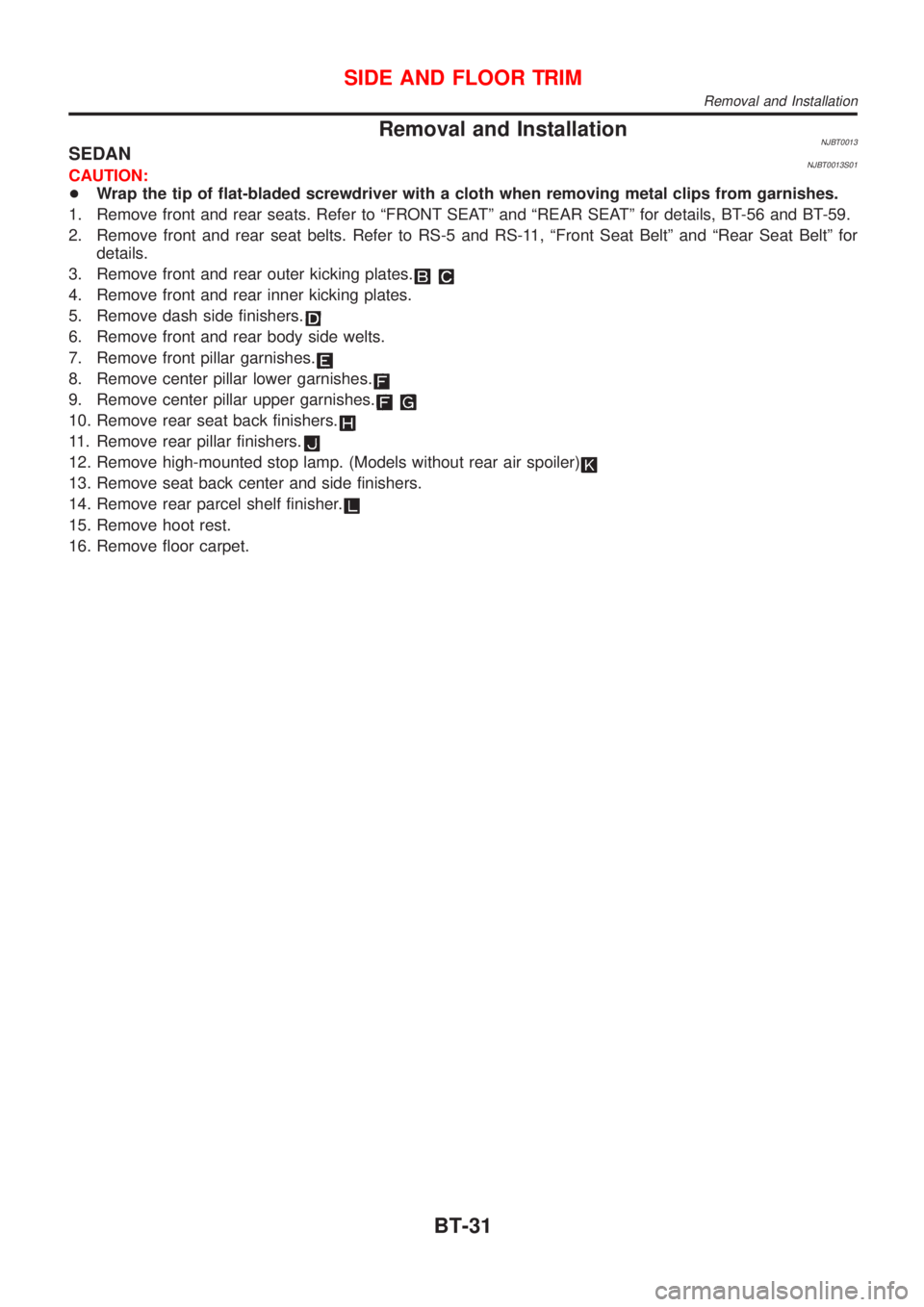
Removal and InstallationNJBT0013SEDANNJBT0013S01CAUTION:
+Wrap the tip of flat-bladed screwdriver with a cloth when removing metal clips from garnishes.
1. Remove front and rear seats. Refer to ªFRONT SEATº and ªREAR SEATº for details, BT-56 and BT-59.
2. Remove front and rear seat belts. Refer to RS-5 and RS-11, ªFront Seat Beltº and ªRear Seat Beltº for
details.
3. Remove front and rear outer kicking plates.
4. Remove front and rear inner kicking plates.
5. Remove dash side finishers.
6. Remove front and rear body side welts.
7. Remove front pillar garnishes.
8. Remove center pillar lower garnishes.
9. Remove center pillar upper garnishes.
10. Remove rear seat back finishers.
11. Remove rear pillar finishers.
12. Remove high-mounted stop lamp. (Models without rear air spoiler)
13. Remove seat back center and side finishers.
14. Remove rear parcel shelf finisher.
15. Remove hoot rest.
16. Remove floor carpet.
SIDE AND FLOOR TRIM
Removal and Installation
BT-31
Page 1928 of 2493
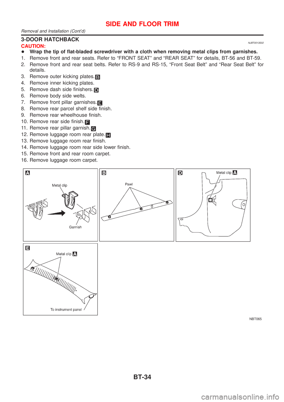
3-DOOR HATCHBACKNJBT0013S02CAUTION:
+Wrap the tip of flat-bladed screwdriver with a cloth when removing metal clips from garnishes.
1. Remove front and rear seats. Refer to ªFRONT SEATº and ªREAR SEATº for details, BT-56 and BT-59.
2. Remove front and rear seat belts. Refer to RS-9 and RS-15, ªFront Seat Beltº and ªRear Seat Beltº for
details.
3. Remove outer kicking plates.
4. Remove inner kicking plates.
5. Remove dash side finishers.
6. Remove body side welts.
7. Remove front pillar garnishes.
8. Remove rear parcel shelf side finish.
9. Remove rear wheelhouse finish.
10. Remove rear side finish.
11. Remove rear pillar garnish.
12. Remove luggage room rear plate.
13. Remove luggage room rear finish.
14. Remove luggage room rear side lower finish.
15. Remove front and rear room carpet.
16. Remove luggage room carpet.
NBT065
SIDE AND FLOOR TRIM
Removal and Installation (Cont'd)
BT-34
Page 1930 of 2493
5-DOOR HATCHBACKNJBT0013S03CAUTION:
+Wrap the tip of flat-bladed screwdriver with a cloth when removing metal clips from garnishes.
1. Remove front and rear seats. Refer to ªFRONT SEATº and ªREAR SEATº for details, BT-56 and BT-59.
2. Remove front and rear seat belts. Refer to RS-7 and RS-15, ªFront Seat Beltº and ªRear Seat Beltº for
details.
3. Remove front and rear outer kicking plates.
4. Remove front and rear inner kicking plates.
5. Remove dash side finishers.
6. Remove front and rear body side welts.
7. Remove front pillar garnishes.
8. Remove center pillar lower garnishes.
9. Remove center pillar upper garnishes.
10. Remove rear parcel shelf side finish.
11. Remove rear pillar garnish.
12. Remove rear wheelhouse finish.
13. Remove luggage room rear plate.
14. Remove luggage room rear finish.
15. Remove luggage room rear side lower finish.
16. Remove front and rear room carpet.
17. Remove luggage room carpet.
SIDE AND FLOOR TRIM
Removal and Installation (Cont'd)
BT-36
Page 1937 of 2493
Removal and InstallationNJBT00151. Remove rear seat. Refer to ªREAR SEATº for details, BT-59.
2. Remove shoulder anchor bolts. Refer to RS-5, ªFront Seat Beltº for details.
3. Remove front pillar garnishes, center pillar upper garnishes, center pillar lower garnishes and rear pillar
garnishes. Refer to ªSIDE AND FLOOR TRIMº for details, BT-31.
4. Push back the front seat back.
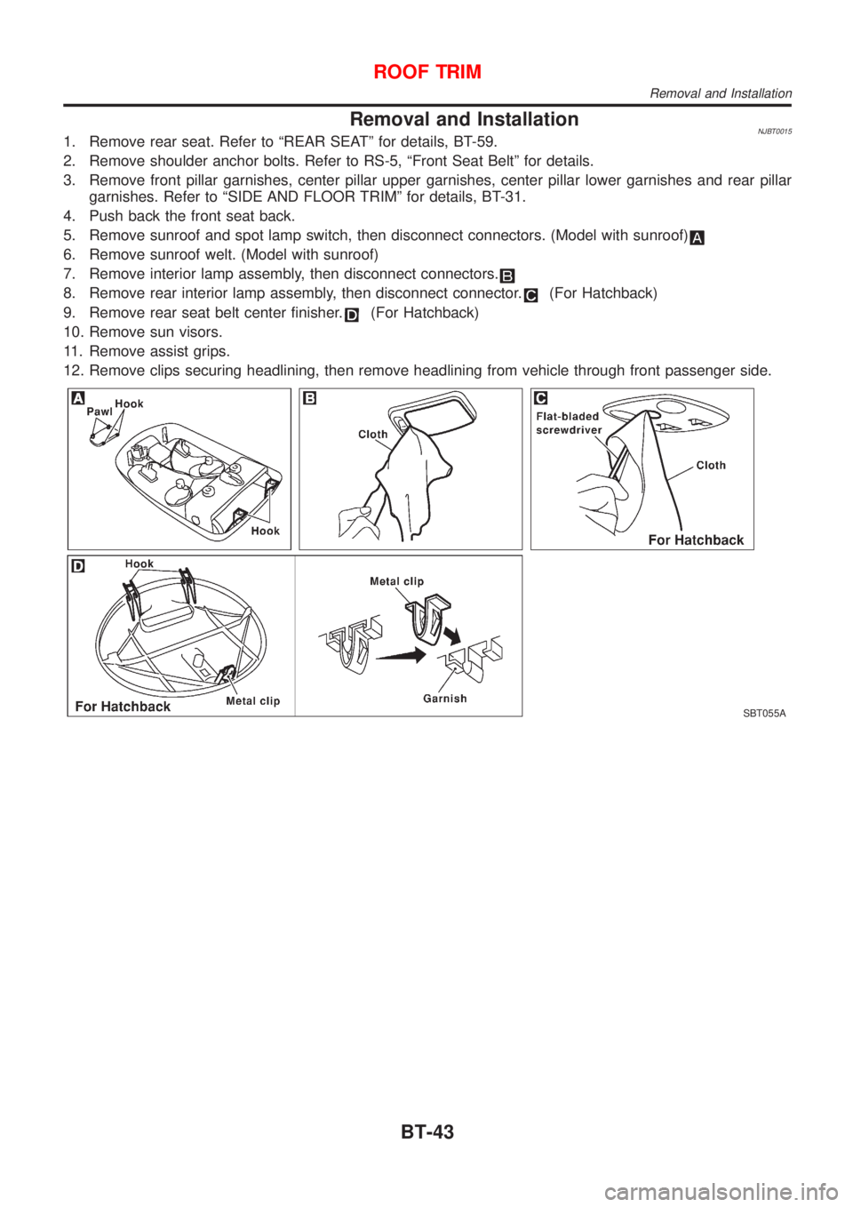
5. Remove sunroof and spot lamp switch, then disconnect connectors. (Model with sunroof)
6. Remove sunroof welt. (Model with sunroof)
7. Remove interior lamp assembly, then disconnect connectors.
8. Remove rear interior lamp assembly, then disconnect connector.(For Hatchback)
9. Remove rear seat belt center finisher.
(For Hatchback)
10. Remove sun visors.
11. Remove assist grips.
12. Remove clips securing headlining, then remove headlining from vehicle through front passenger side.
SBT055A
ROOF TRIM
Removal and Installation
BT-43
Page 1950 of 2493
Removal and InstallationNJBT0018+When removing or installing the seat trim, carefully handle it to keep dirt out and avoid damage.
HFor Wiring Diagram, refer to EL-163, ªWiring Diagram Ð HEATED SEAT к.
CAUTION:
+Before removing the front seat, turn the ignition switch off, disconnect both battery cables and wait
at least 3 minutes.
+Do not drop, tilt, or bump the side air bag module installed in the seat. Always handle it with care.
+Disconnect the side air bag harness connector and heated seat harness connector from under the
seat before removing the seat.
+Disconnect the side air bag harness connector before removing the seat back. Refer to RS-33,
ªFront Side Air Bag Moduleº for details.
FRONT SEAT
Removal and Installation
BT-56