2001 NISSAN ALMERA N16 Tail
[x] Cancel search: TailPage 385 of 2493

TEST ITEM CONDITION JUDGEMENT CHECK ITEM (REMEDY)
IACV-AAC/V
OPENING+Engine: After warming up, idle
the engine.
+Change the IACV-AAC valve
opening steps using CONSULT-
II.Engine speed changes according
to the opening steps.+Harness and connector
+IACV-AAC valve
POWER BAL-
ANCE+Engine: After warming up, idle
the engine.
+Air conditioner switch ªOFFº
+Shift lever ªNº
+Cut off each injector signal one
at a time using CONSULT-II.Engine runs rough or dies.+Harness and connector
+Compression
+Injectors
+Power transistor
+Spark plugs
+Ignition coils
COOLING FAN+Ignition switch: ON
+Turn the cooling fan ªONº and
ªOFFº using CONSULT-II.Cooling fan moves and stops.+Harness and connector
+Cooling fan motor
ENG COOLANT
TEMP+Engine: Return to the original
trouble condition
+Change the engine coolant tem-
perature indication using CON-
SULT-II.If trouble symptom disappears, see
CHECK ITEM.+Harness and connector
+Engine coolant temperature sen-
sor
+Fuel injectors
FUEL PUMP
RELAY+Ignition switch: ON
(Engine stopped)
+Turn the fuel pump relay ªONº
and ªOFFº using CONSULT-II
and listen to operating sound.Fuel pump relay makes the operat-
ing sound.+Harness and connector
+Fuel pump relay
EGR VOL
CONT/V
(If so equipped)+Engine: After warming up, idle
the engine.
+Change the EGR volume control
valve opening step using CON-
SULT-II.Engine speed changes according
to the opening step.+Harness and connector
+EGR volume control valve
VALVE TIMING
SOL+Ignition switch: ON
+Turn intake valve timing control
solenoid valve ªONº and ªOFFº
using CONSULT-II and listen for
operating sound.Intake valve timing control solenoid
valve makes an operating sound.+Harness and connector
+Intake valve timing control sole-
noid valve
PURG VOL
CONT/V+Engine: After warming up, idle
the engine.
+Change the EVAP canister
purge volume control solenoid
valve opening percent using
CONSULT-II.Engine speed changes according
to the opening percent.+Harness and connector
+EVAP canister purge volume
control solenoid valve
DTC AND SRT CONFIRMATION MODENJEC0034S08This mode is not available for models without Euro-OBD system.
SRT STATUS ModeNJEC0034S0801For details, refer to ªSYSTEM READINESS TEST (SRT) CODEº,
EC-60.
SRT Work Support ModeNJEC0034S0803This mode enables a technician to drive a vehicle to set the SRT
while monitoring the SRT status.
ON BOARD DIAGNOSTIC SYSTEM DESCRIPTIONQG
CONSULT-II (Cont'd)
EC-89
Page 389 of 2493

FUNCTIONNJEC0035S03
Diagnostic test mode Function
MODE 1 READINESS TESTSThis mode gains access to current emission-related data values, including analog
inputs and outputs, digital inputs and outputs, distance traveled while MI is activated
and system status information.
MODE 2 (FREEZE DATA)This mode gains access to emission-related data value which were stored by ECM
during the freeze frame. (For details, refer to ªFreeze Frame Dataº, EC-84.)
MODE 3 DTCsThis mode gains access to emission-related power train trouble codes which were
stored by ECM.
MODE 4 CLEAR DIAG INFOThis mode can clear all emission-related diagnostic information. This includes:
+Clear number of diagnostic trouble codes (MODE 1)
+Clear diagnostic trouble codes (MODE 3)
+Clear trouble code for freeze frame data (MODE 1)
+Clear freeze frame data (MODE 2)
+Reset status of system monitoring test (MODE 1)
+Clear on board monitoring test results (MODE 6 and 7)
MODE 6 (ON BOARD TESTS)This mode accesses the results of on board diagnostic monitoring tests of specific
components/systems that are not continuously monitored.
MODE 7 (ON BOARD TESTS)This mode enables the off board test drive to obtain test results for emission-related
powertrain components/systems that are continuously monitored during normal driving
conditions.
MODE 8 Ð This mode is not applicable on this vehicle.
MODE 9 (CALIBRATION ID)This mode enables the off-board (External test equipment) to request specific vehicle
information such as Vehicle Identification Number (VIN) and Calibration IDs.
ON BOARD DIAGNOSTIC SYSTEM DESCRIPTIONQG
Generic Scan Tool (GST) (Cont'd)
EC-93
Page 393 of 2493
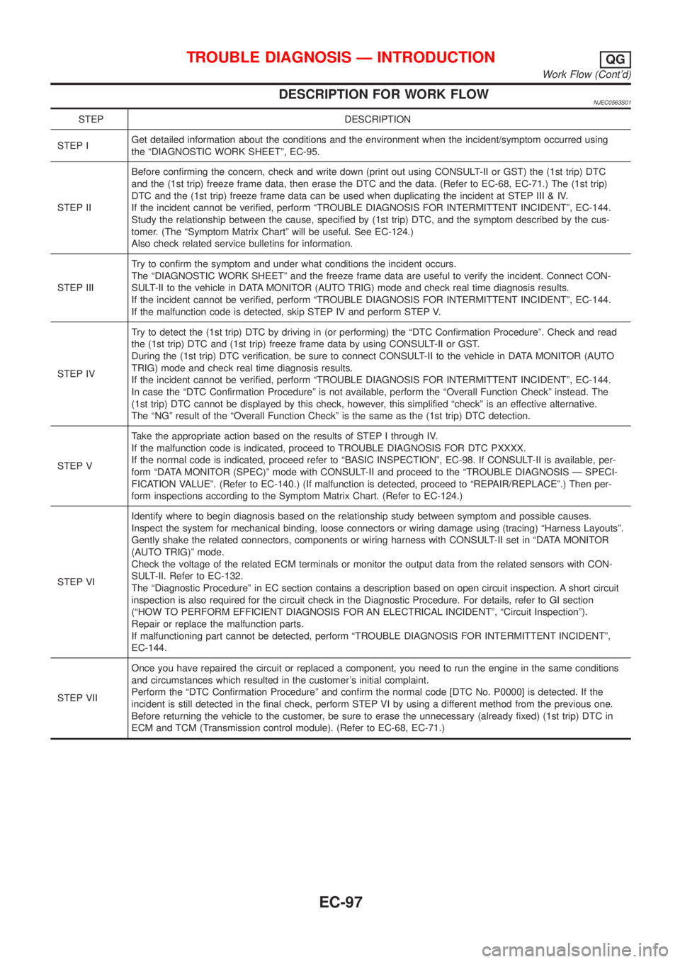
DESCRIPTION FOR WORK FLOWNJEC0563S01
STEP DESCRIPTION
STEP IGet detailed information about the conditions and the environment when the incident/symptom occurred using
the ªDIAGNOSTIC WORK SHEETº, EC-95.
STEP IIBefore confirming the concern, check and write down (print out using CONSULT-II or GST) the (1st trip) DTC
and the (1st trip) freeze frame data, then erase the DTC and the data. (Refer to EC-68, EC-71.) The (1st trip)
DTC and the (1st trip) freeze frame data can be used when duplicating the incident at STEP III & IV.
If the incident cannot be verified, perform ªTROUBLE DIAGNOSIS FOR INTERMITTENT INCIDENTº, EC-144.
Study the relationship between the cause, specified by (1st trip) DTC, and the symptom described by the cus-
tomer. (The ªSymptom Matrix Chartº will be useful. See EC-124.)
Also check related service bulletins for information.
STEP IIITry to confirm the symptom and under what conditions the incident occurs.
The ªDIAGNOSTIC WORK SHEETº and the freeze frame data are useful to verify the incident. Connect CON-
SULT-II to the vehicle in DATA MONITOR (AUTO TRIG) mode and check real time diagnosis results.
If the incident cannot be verified, perform ªTROUBLE DIAGNOSIS FOR INTERMITTENT INCIDENTº, EC-144.
If the malfunction code is detected, skip STEP IV and perform STEP V.
STEP IVTry to detect the (1st trip) DTC by driving in (or performing) the ªDTC Confirmation Procedureº. Check and read
the (1st trip) DTC and (1st trip) freeze frame data by using CONSULT-II or GST.
During the (1st trip) DTC verification, be sure to connect CONSULT-II to the vehicle in DATA MONITOR (AUTO
TRIG) mode and check real time diagnosis results.
If the incident cannot be verified, perform ªTROUBLE DIAGNOSIS FOR INTERMITTENT INCIDENTº, EC-144.
In case the ªDTC Confirmation Procedureº is not available, perform the ªOverall Function Checkº instead. The
(1st trip) DTC cannot be displayed by this check, however, this simplified ªcheckº is an effective alternative.
The ªNGº result of the ªOverall Function Checkº is the same as the (1st trip) DTC detection.
STEP VTake the appropriate action based on the results of STEP I through IV.
If the malfunction code is indicated, proceed to TROUBLE DIAGNOSIS FOR DTC PXXXX.
If the normal code is indicated, proceed refer to ªBASIC INSPECTIONº, EC-98. If CONSULT-II is available, per-
form ªDATA MONITOR (SPEC)º mode with CONSULT-II and proceed to the ªTROUBLE DIAGNOSIS Ð SPECI-
FICATION VALUEº. (Refer to EC-140.) (If malfunction is detected, proceed to ªREPAIR/REPLACEº.) Then per-
form inspections according to the Symptom Matrix Chart. (Refer to EC-124.)
STEP VIIdentify where to begin diagnosis based on the relationship study between symptom and possible causes.
Inspect the system for mechanical binding, loose connectors or wiring damage using (tracing) ªHarness Layoutsº.
Gently shake the related connectors, components or wiring harness with CONSULT-II set in ªDATA MONITOR
(AUTO TRIG)º mode.
Check the voltage of the related ECM terminals or monitor the output data from the related sensors with CON-
SULT-II. Refer to EC-132.
The ªDiagnostic Procedureº in EC section contains a description based on open circuit inspection. A short circuit
inspection is also required for the circuit check in the Diagnostic Procedure. For details, refer to GI section
(ªHOW TO PERFORM EFFICIENT DIAGNOSIS FOR AN ELECTRICAL INCIDENTº, ªCircuit Inspectionº).
Repair or replace the malfunction parts.
If malfunctioning part cannot be detected, perform ªTROUBLE DIAGNOSIS FOR INTERMITTENT INCIDENTº,
EC-144.
STEP VIIOnce you have repaired the circuit or replaced a component, you need to run the engine in the same conditions
and circumstances which resulted in the customer's initial complaint.
Perform the ªDTC Confirmation Procedureº and confirm the normal code [DTC No. P0000] is detected. If the
incident is still detected in the final check, perform STEP VI by using a different method from the previous one.
Before returning the vehicle to the customer, be sure to erase the unnecessary (already fixed) (1st trip) DTC in
ECM and TCM (Transmission control module). (Refer to EC-68, EC-71.)
TROUBLE DIAGNOSIS Ð INTRODUCTIONQG
Work Flow (Cont'd)
EC-97
Page 639 of 2493
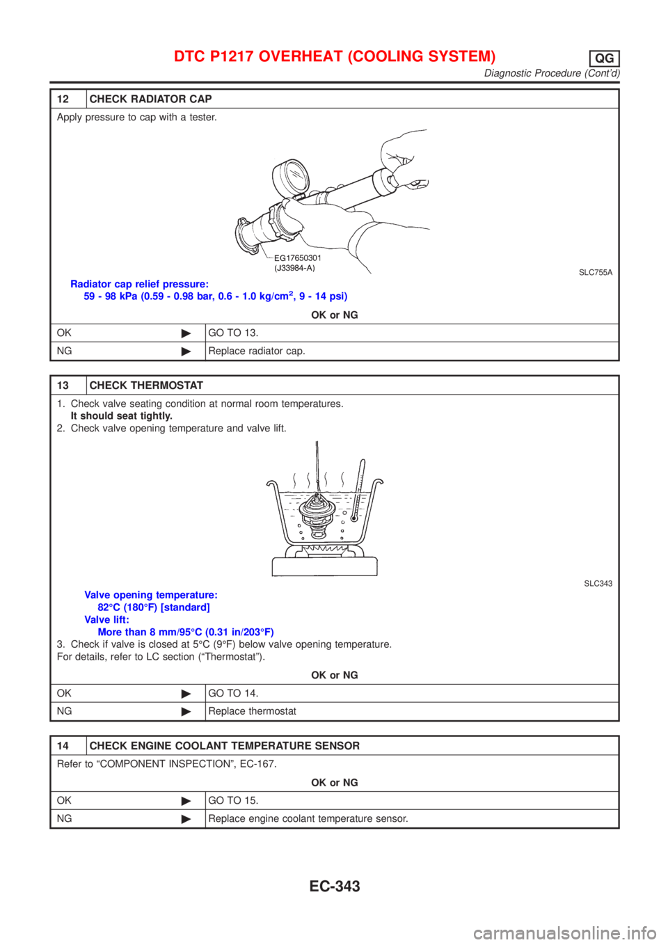
12 CHECK RADIATOR CAP
Apply pressure to cap with a tester.
SLC755A
Radiator cap relief pressure:
59 - 98 kPa (0.59 - 0.98 bar, 0.6 - 1.0 kg/cm2,9-14psi)
OK or NG
OK©GO TO 13.
NG©Replace radiator cap.
13 CHECK THERMOSTAT
1. Check valve seating condition at normal room temperatures.
It should seat tightly.
2. Check valve opening temperature and valve lift.
SLC343
Valve opening temperature:
82ÉC (180ÉF) [standard]
Valve lift:
More than 8 mm/95ÉC (0.31 in/203ÉF)
3. Check if valve is closed at 5ÉC (9ÉF) below valve opening temperature.
For details, refer to LC section (ªThermostatº).
OK or NG
OK©GO TO 14.
NG©Replace thermostat
14 CHECK ENGINE COOLANT TEMPERATURE SENSOR
Refer to ªCOMPONENT INSPECTIONº, EC-167.
OK or NG
OK©GO TO 15.
NG©Replace engine coolant temperature sensor.
DTC P1217 OVERHEAT (COOLING SYSTEM)QG
Diagnostic Procedure (Cont'd)
EC-343
Page 795 of 2493
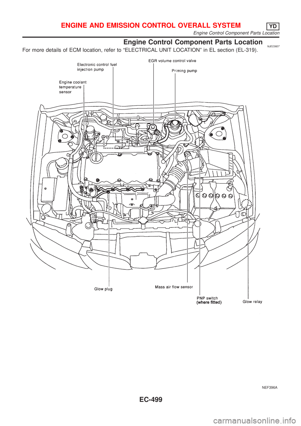
Engine Control Component Parts LocationNJEC0607For more details of ECM location, refer to ªELECTRICAL UNIT LOCATIONº in EL section (EL-319).
NEF396A
ENGINE AND EMISSION CONTROL OVERALL SYSTEMYD
Engine Control Component Parts Location
EC-499
Page 831 of 2493
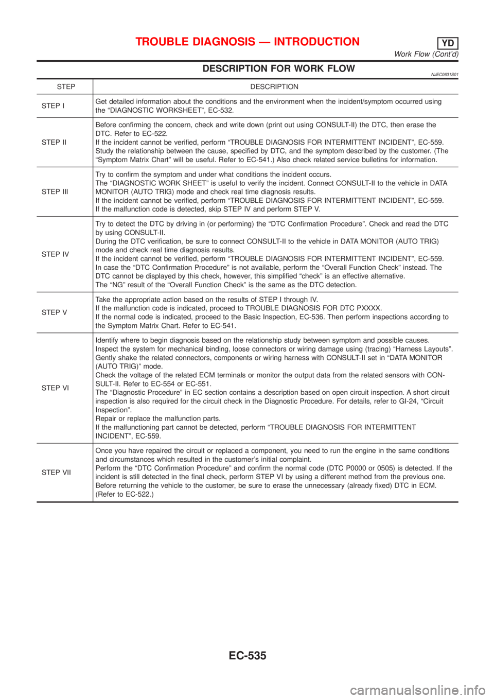
DESCRIPTION FOR WORK FLOWNJEC0631S01
STEP DESCRIPTION
STEP IGet detailed information about the conditions and the environment when the incident/symptom occurred using
the ªDIAGNOSTIC WORKSHEETº, EC-532.
STEP IIBefore confirming the concern, check and write down (print out using CONSULT-II) the DTC, then erase the
DTC. Refer to EC-522.
If the incident cannot be verified, perform ªTROUBLE DIAGNOSIS FOR INTERMITTENT INCIDENTº, EC-559.
Study the relationship between the cause, specified by DTC, and the symptom described by the customer. (The
ªSymptom Matrix Chartº will be useful. Refer to EC-541.) Also check related service bulletins for information.
STEP IIITry to confirm the symptom and under what conditions the incident occurs.
The ªDIAGNOSTIC WORK SHEETº is useful to verify the incident. Connect CONSULT-II to the vehicle in DATA
MONITOR (AUTO TRIG) mode and check real time diagnosis results.
If the incident cannot be verified, perform ªTROUBLE DIAGNOSIS FOR INTERMITTENT INCIDENTº, EC-559.
If the malfunction code is detected, skip STEP IV and perform STEP V.
STEP IVTry to detect the DTC by driving in (or performing) the ªDTC Confirmation Procedureº. Check and read the DTC
by using CONSULT-II.
During the DTC verification, be sure to connect CONSULT-II to the vehicle in DATA MONITOR (AUTO TRIG)
mode and check real time diagnosis results.
If the incident cannot be verified, perform ªTROUBLE DIAGNOSIS FOR INTERMITTENT INCIDENTº, EC-559.
In case the ªDTC Confirmation Procedureº is not available, perform the ªOverall Function Checkº instead. The
DTC cannot be displayed by this check, however, this simplified ªcheckº is an effective alternative.
The ªNGº result of the ªOverall Function Checkº is the same as the DTC detection.
STEP VTake the appropriate action based on the results of STEP I through IV.
If the malfunction code is indicated, proceed to TROUBLE DIAGNOSIS FOR DTC PXXXX.
If the normal code is indicated, proceed to the Basic Inspection, EC-536. Then perform inspections according to
the Symptom Matrix Chart. Refer to EC-541.
STEP VIIdentify where to begin diagnosis based on the relationship study between symptom and possible causes.
Inspect the system for mechanical binding, loose connectors or wiring damage using (tracing) ªHarness Layoutsº.
Gently shake the related connectors, components or wiring harness with CONSULT-II set in ªDATA MONITOR
(AUTO TRIG)º mode.
Check the voltage of the related ECM terminals or monitor the output data from the related sensors with CON-
SULT-II. Refer to EC-554 or EC-551.
The ªDiagnostic Procedureº in EC section contains a description based on open circuit inspection. A short circuit
inspection is also required for the circuit check in the Diagnostic Procedure. For details, refer to GI-24, ªCircuit
Inspectionº.
Repair or replace the malfunction parts.
If the malfunctioning part cannot be detected, perform ªTROUBLE DIAGNOSIS FOR INTERMITTENT
INCIDENTº, EC-559.
STEP VIIOnce you have repaired the circuit or replaced a component, you need to run the engine in the same conditions
and circumstances which resulted in the customer's initial complaint.
Perform the ªDTC Confirmation Procedureº and confirm the normal code (DTC P0000 or 0505) is detected. If the
incident is still detected in the final check, perform STEP VI by using a different method from the previous one.
Before returning the vehicle to the customer, be sure to erase the unnecessary (already fixed) DTC in ECM.
(Refer to EC-522.)
TROUBLE DIAGNOSIS Ð INTRODUCTIONYD
Work Flow (Cont'd)
EC-535
Page 922 of 2493
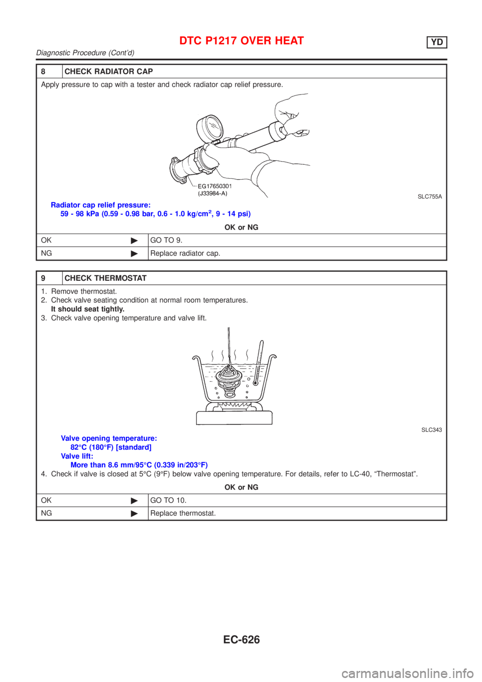
8 CHECK RADIATOR CAP
Apply pressure to cap with a tester and check radiator cap relief pressure.
SLC755A
Radiator cap relief pressure:
59 - 98 kPa (0.59 - 0.98 bar, 0.6 - 1.0 kg/cm2,9-14psi)
OK or NG
OK©GO TO 9.
NG©Replace radiator cap.
9 CHECK THERMOSTAT
1. Remove thermostat.
2. Check valve seating condition at normal room temperatures.
It should seat tightly.
3. Check valve opening temperature and valve lift.
SLC343
Valve opening temperature:
82ÉC (180ÉF) [standard]
Valve lift:
More than 8.6 mm/95ÉC (0.339 in/203ÉF)
4. Check if valve is closed at 5ÉC (9ÉF) below valve opening temperature. For details, refer to LC-40, ªThermostatº.
OK or NG
OK©GO TO 10.
NG©Replace thermostat.
DTC P1217 OVER HEATYD
Diagnostic Procedure (Cont'd)
EC-626
Page 1196 of 2493

+The fluid has an odor, is discolored, and there is no evidence of metal or clutch facing particles.
+The threads in one or more of the converter bolt holes are damaged.
+Transaxle failure did not display evidence of damaged or worn internal parts, steel particles or clutch plate
lining material in unit and inside the fluid filter.
+Vehicle has been exposed to high mileage (only). The exception may be where the torque converter clutch
dampener plate lining has seen excess wear by vehicles operated in heavy and/or constant traffic, such
as taxi, delivery or police use.
EURO-OBD SELF-DIAGNOSIS Ð EURO-OBD ÐNJAT0247S04+A/T self-diagnosis is performed by the TCM in combination with the ECM. The results can be read through
the blinking pattern of the O/D OFF indicator or the malfunction indicator (MI). Refer to the table on AT-53
for the indicator used to display each self-diagnostic result.
+The self-diagnostic results indicated by the MI are automatically stored in both the ECM and TCM memo-
ries.
Always perform the procedure ªHOW TO ERASE DTCº on AT-50 to complete the repair and avoid
unnecessary blinking of the MI.
+The following self-diagnostic items can be detected using ECM self-diagnostic results mode* only when
the O/D OFF indicator lamp does not indicate any malfunctions.
þ PNP switch
þ A/T 1st, 2nd, 3rd, or 4th gear function
*: For details of EURO-OBD, refer to EC-57, ªON BOARD DIAGNOSTIC SYSTEM DESCRIPTIONº.
+Certain systems and components, especially those related to EURO-OBD, may use a new style
slide-locking type harness connector.
For description and how to disconnect, refer to EL-5, ªHARNESS CONNECTORº.
Wiring Diagrams and Trouble DiagnosisNJAT0248When you read wiring diagrams, refer to the following:
+GI-12, ªHOW TO READ WIRING DIAGRAMSº
+EL-10, ªPOWER SUPPLY ROUTINGº
When you perform trouble diagnosis, refer to the following:
+GI-32, ªHOW TO FOLLOW TEST GROUP IN TROUBLE DIAGNOSISº
+GI-21, ªHOW TO PERFORM EFFICIENT DIAGNOSIS FOR AN ELECTRICAL INCIDENTº
PRECAUTIONS
Service Notice or Precautions (Cont'd)
AT-10