2001 NISSAN ALMERA N16 Tail
[x] Cancel search: TailPage 1952 of 2493
Heated SeatNJBT0036HFor Wiring Diagram, refer to EL-163, ªHEATED SEATº for details.
SBT014A
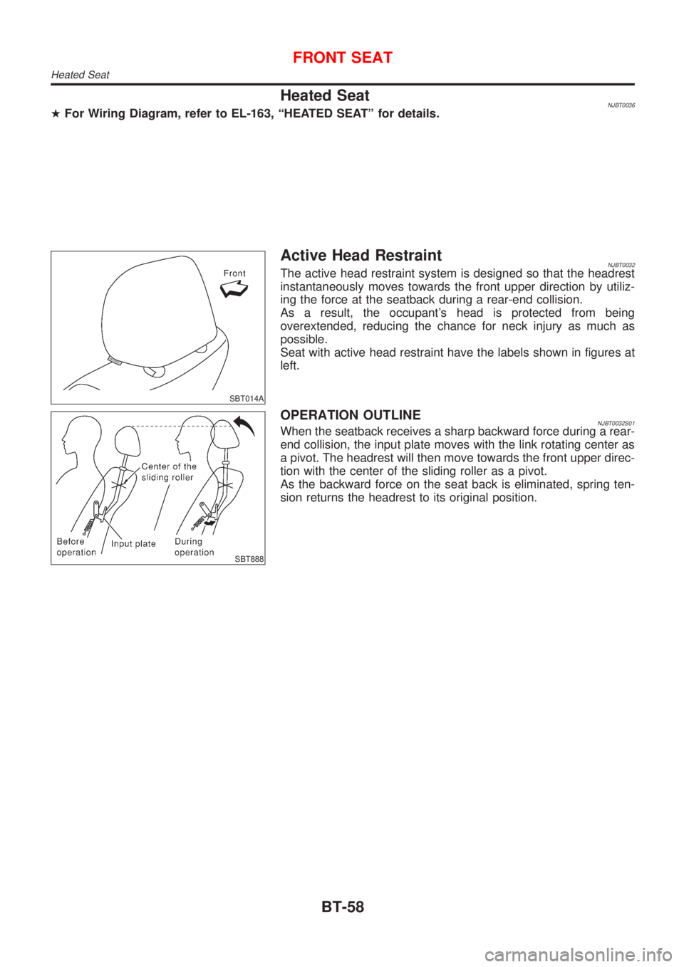
Active Head RestraintNJBT0032The active head restraint system is designed so that the headrest
instantaneously moves towards the front upper direction by utiliz-
ing the force at the seatback during a rear-end collision.
As a result, the occupant's head is protected from being
overextended, reducing the chance for neck injury as much as
possible.
Seat with active head restraint have the labels shown in figures at
left.
SBT888
OPERATION OUTLINENJBT0032S01When the seatback receives a sharp backward force during a rear-
end collision, the input plate moves with the link rotating center as
a pivot. The headrest will then move towards the front upper direc-
tion with the center of the sliding roller as a pivot.
As the backward force on the seat back is eliminated, spring ten-
sion returns the headrest to its original position.
FRONT SEAT
Heated Seat
BT-58
Page 1960 of 2493
DRAIN HOSESNJBT0022S04
SBT005A
SBT333
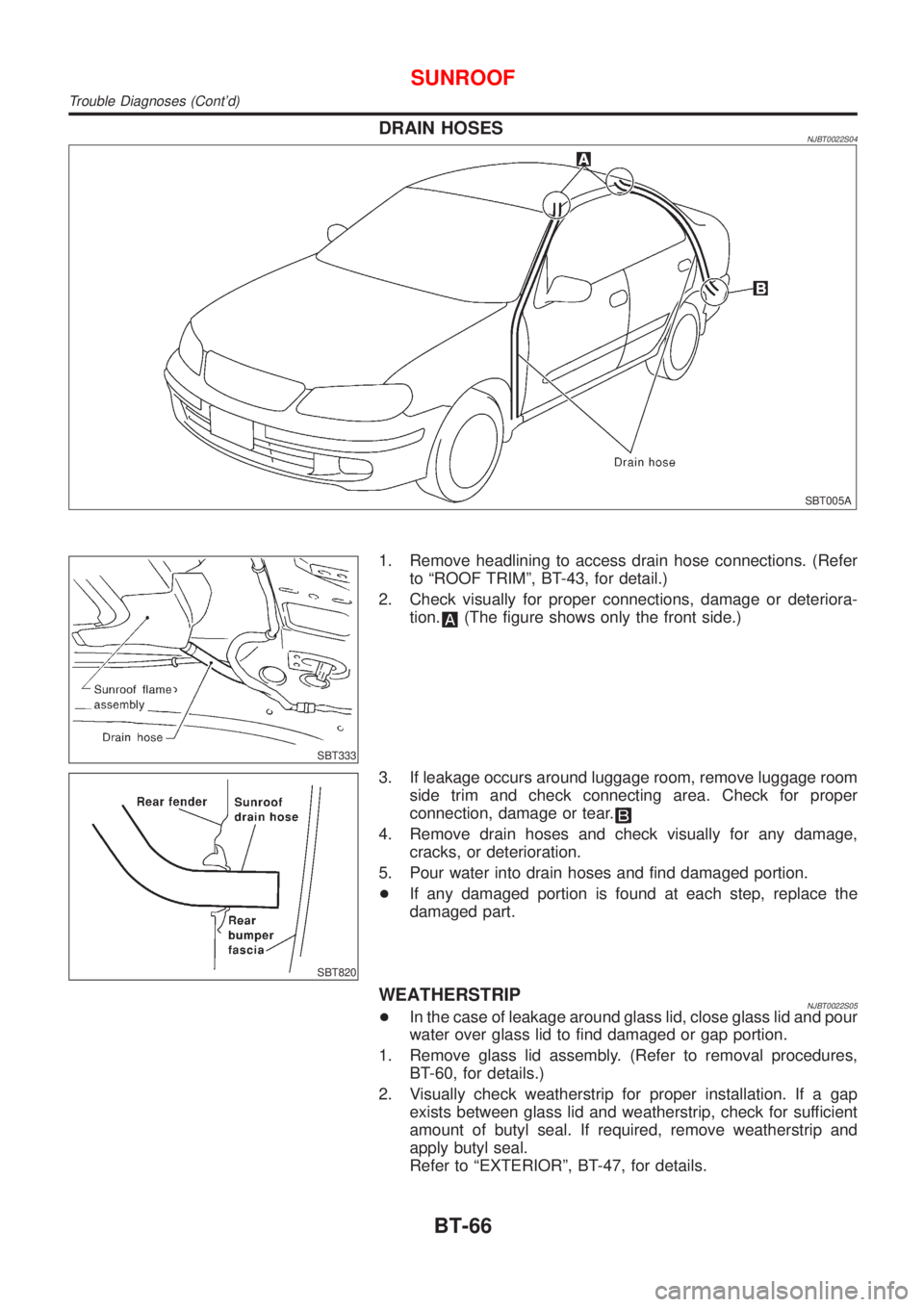
1. Remove headlining to access drain hose connections. (Refer
to ªROOF TRIMº, BT-43, for detail.)
2. Check visually for proper connections, damage or deteriora-
tion.
(The figure shows only the front side.)
SBT820
3. If leakage occurs around luggage room, remove luggage room
side trim and check connecting area. Check for proper
connection, damage or tear.
4. Remove drain hoses and check visually for any damage,
cracks, or deterioration.
5. Pour water into drain hoses and find damaged portion.
+If any damaged portion is found at each step, replace the
damaged part.
WEATHERSTRIPNJBT0022S05+In the case of leakage around glass lid, close glass lid and pour
water over glass lid to find damaged or gap portion.
1. Remove glass lid assembly. (Refer to removal procedures,
BT-60, for details.)
2. Visually check weatherstrip for proper installation. If a gap
exists between glass lid and weatherstrip, check for sufficient
amount of butyl seal. If required, remove weatherstrip and
apply butyl seal.
Refer to ªEXTERIORº, BT-47, for details.
SUNROOF
Trouble Diagnoses (Cont'd)
BT-66
Page 1961 of 2493
3. Check weatherstrip visually for any damage, deterioration, or
flattening.
+If any damage is found, replace weatherstrip.
CAUTION:
Do not remove weatherstrip except when replacing, or filling
up butyl seal.
LINK AND WIRE ASSEMBLYNJBT0022S06NOTE:
Before replacing a suspect part, carefully ensure it is the source of
noise being experienced.
1. Check link to determine if coating film has peeled off to such
an extent that substrate is visible. Check also to determine if
link is the source of noise. If it is, replace it.
2. Visually check to determine if a sufficient amount of petroleum
jelly has been applied to wire or rail groove. If not, add petro-
leum jelly as required.
3. Check wire for any damage or deterioration. If any damage is
found, remove rear guide (refer to removal procedures, BT-60,
for details), then replace wire.
SUNROOF
Trouble Diagnoses (Cont'd)
BT-67
Page 1966 of 2493
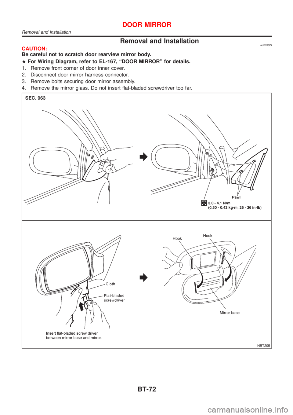
Removal and InstallationNJBT0024CAUTION:
Be careful not to scratch door rearview mirror body.
HFor Wiring Diagram, refer to EL-167, ªDOOR MIRRORº for details.
1. Remove front corner of door inner cover.
2. Disconnect door mirror harness connector.
3. Remove bolts securing door mirror assembly.
4. Remove the mirror glass. Do not insert flat-bladed screwdriver too far.
NBT205
DOOR MIRROR
Removal and Installation
BT-72
Page 2113 of 2493
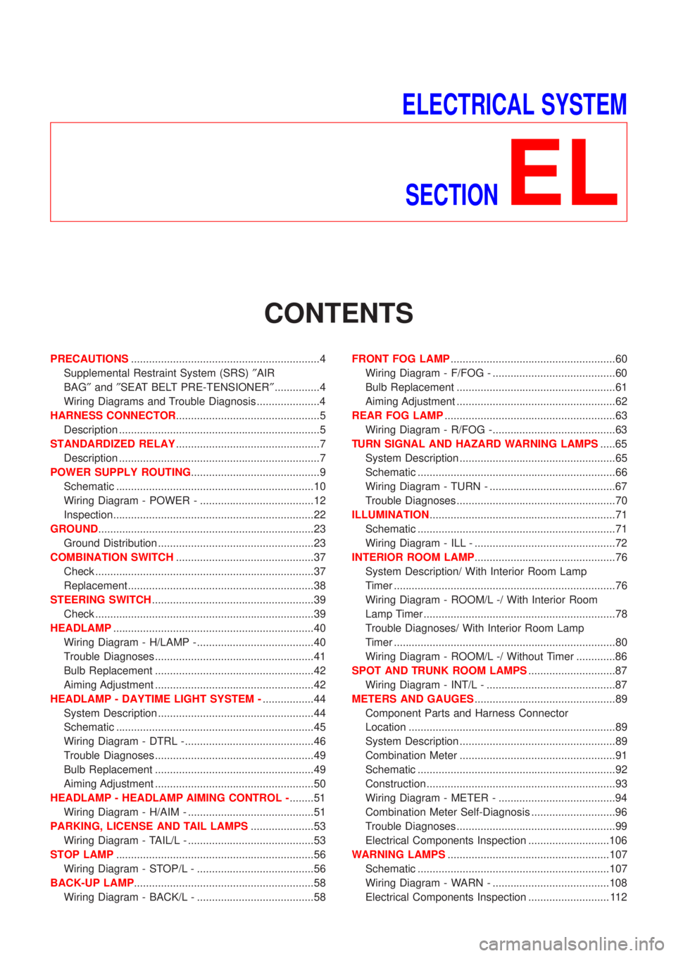
ELECTRICAL SYSTEM
SECTION
EL
CONTENTS
PRECAUTIONS...............................................................4
Supplemental Restraint System (SRS)²AIR
BAG²and²SEAT BELT PRE-TENSIONER²...............4
Wiring Diagrams and Trouble Diagnosis .....................4
HARNESS CONNECTOR................................................5
Description ...................................................................5
STANDARDIZED RELAY................................................7
Description ...................................................................7
POWER SUPPLY ROUTING...........................................9
Schematic ..................................................................10
Wiring Diagram - POWER - ......................................12
Inspection...................................................................22
GROUND........................................................................23
Ground Distribution ....................................................23
COMBINATION SWITCH..............................................37
Check .........................................................................37
Replacement ..............................................................38
STEERING SWITCH......................................................39
Check .........................................................................39
HEADLAMP...................................................................40
Wiring Diagram - H/LAMP -.......................................40
Trouble Diagnoses.....................................................41
Bulb Replacement .....................................................42
Aiming Adjustment .....................................................42
HEADLAMP - DAYTIME LIGHT SYSTEM -.................44
System Description ....................................................44
Schematic ..................................................................45
Wiring Diagram - DTRL - ...........................................46
Trouble Diagnoses.....................................................49
Bulb Replacement .....................................................49
Aiming Adjustment .....................................................50
HEADLAMP - HEADLAMP AIMING CONTROL -........51
Wiring Diagram - H/AIM - ..........................................51
PARKING, LICENSE AND TAIL LAMPS.....................53
Wiring Diagram - TAIL/L - ..........................................53
STOP LAMP..................................................................56
Wiring Diagram - STOP/L - .......................................56
BACK-UP LAMP............................................................58
Wiring Diagram - BACK/L - .......................................58FRONT FOG LAMP.......................................................60
Wiring Diagram - F/FOG - .........................................60
Bulb Replacement .....................................................61
Aiming Adjustment .....................................................62
REAR FOG LAMP.........................................................63
Wiring Diagram - R/FOG -.........................................63
TURN SIGNAL AND HAZARD WARNING LAMPS.....65
System Description ....................................................65
Schematic ..................................................................66
Wiring Diagram - TURN - ..........................................67
Trouble Diagnoses.....................................................70
ILLUMINATION..............................................................71
Schematic ..................................................................71
Wiring Diagram - ILL - ...............................................72
INTERIOR ROOM LAMP...............................................76
System Description/ With Interior Room Lamp
Timer ..........................................................................76
Wiring Diagram - ROOM/L -/ With Interior Room
Lamp Timer ................................................................78
Trouble Diagnoses/ With Interior Room Lamp
Timer ..........................................................................80
Wiring Diagram - ROOM/L -/ Without Timer .............86
SPOT AND TRUNK ROOM LAMPS.............................87
Wiring Diagram - INT/L - ...........................................87
METERS AND GAUGES...............................................89
Component Parts and Harness Connector
Location .....................................................................89
System Description ....................................................89
Combination Meter ....................................................91
Schematic ..................................................................92
Construction ...............................................................93
Wiring Diagram - METER - .......................................94
Combination Meter Self-Diagnosis ............................96
Trouble Diagnoses.....................................................99
Electrical Components Inspection ...........................106
WARNING LAMPS......................................................107
Schematic ................................................................107
Wiring Diagram - WARN - .......................................108
Electrical Components Inspection ........................... 112
Page 2154 of 2493
SEL921W
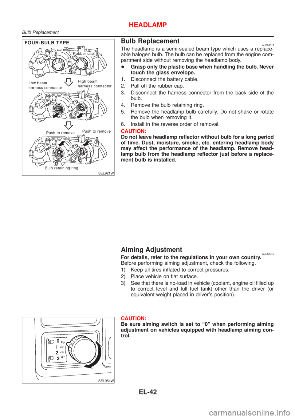
Bulb ReplacementNJEL0015The headlamp is a semi-sealed beam type which uses a replace-
able halogen bulb. The bulb can be replaced from the engine com-
partment side without removing the headlamp body.
+Grasp only the plastic base when handling the bulb. Never
touch the glass envelope.
1. Disconnect the battery cable.
2. Pull off the rubber cap.
3. Disconnect the harness connector from the back side of the
bulb.
4. Remove the bulb retaining ring.
5. Remove the headlamp bulb carefully. Do not shake or rotate
the bulb when removing it.
6. Install in the reverse order of removal.
CAUTION:
Do not leave headlamp reflector without bulb for a long period
of time. Dust, moisture, smoke, etc. entering headlamp body
may affect the performance of the headlamp. Remove head-
lamp bulb from the headlamp reflector just before a replace-
ment bulb is installed.
Aiming AdjustmentNJEL0016For details, refer to the regulations in your own country.
Before performing aiming adjustment, check the following.
1) Keep all tires inflated to correct pressures.
2) Place vehicle on flat surface.
3) See that there is no-load in vehicle (coolant, engine oil filled up
to correct level and full fuel tank) other than the driver (or
equivalent weight placed in driver's position).
SEL984W
CAUTION:
Be sure aiming switch is set to ª0º when performing aiming
adjustment on vehicles equipped with headlamp aiming con-
trol.
HEADLAMP
Bulb Replacement
EL-42
Page 2156 of 2493
System DescriptionNJEL0351The headlamp system on vehicles for North Europe contains a daytime light unit. The unit activates the fol-
lowing whenever the engine is running with the lighting switch in the OFF position:
+Low beam headlamps
+Parking, license, tail and illumination lamps
Power is supplied at all times
+through 10A fuse (No. 38, located in the fusible link and fuse box)
+to daytime light unit terminal 1 and
+to lighting switch terminal 11.
Power is also supplied at all times
+through 15A fuse (No. 39, located in the fusible link and fuse box)
+to daytime light unit terminal 3 and
+to lighting switch terminal 5.
Power is also supplied at all times
+through 15A fuse (No. 40, located in the fusible link and fuse box)
+to daytime light unit terminal 2 and
+to lighting switch terminal 8.
With the ignition switch in the ON or START position, power is supplied
+through 10A fuse [No. 20, located in the fuse block (J/B)]
+to daytime light unit terminal 7.
With the ignition switch in the START position, power is supplied
+through 10A fuse [No. 21, located in the fuse block (J/B)]
+to daytime light unit terminal 6.
Ground is supplied to daytime light unit terminal 9 through body grounds E30 and E73.
HEADLAMP OPERATION (DAYTIME LIGHT CANCEL OPERATION)NJEL0351S01When the lighting switch is turned to the 1st or 2nd position, power is supplied
+through lighting switch terminal 12,
+to daytime light unit terminal 11.
Then daytime light will be canceled. And the lighting system operation will be the same as no daytime light
system.
DAYTIME LIGHT OPERATIONNJEL0351S02With the engine running and the lighting switch in the OFF position, power is supplied
+from alternator terminal 3
+to daytime light unit terminal 8,
+through daytime light unit terminal 5
+to terminal 3 of headlamp LH,
+through daytime light unit terminal 4
+to terminal 3 of headlamp RH and
+through daytime light unit terminal 10
+to tail lamp and illumination.
Ground is supplied to terminal 2 of each headlamp through body grounds E30 and E73.
HEADLAMP Ð DAYTIME LIGHT SYSTEM Ð
System Description
EL-44
Page 2161 of 2493
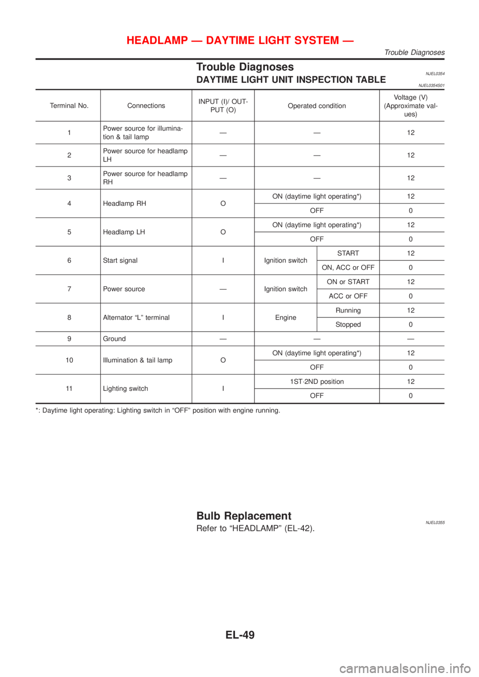
Trouble DiagnosesNJEL0354DAYTIME LIGHT UNIT INSPECTION TABLENJEL0354S01
Terminal No. ConnectionsINPUT (I)/ OUT-
PUT (O)Operated conditionVoltage (V)
(Approximate val-
ues)
1Power source for illumina-
tion & tail lampÐÐ12
2Power source for headlamp
LHÐÐ12
3Power source for headlamp
RHÐÐ12
4 Headlamp RH OON (daytime light operating*) 12
OFF 0
5 Headlamp LH OON (daytime light operating*) 12
OFF 0
6 Start signal I Ignition switchSTART 12
ON, ACC or OFF 0
7 Power source Ð Ignition switchON or START 12
ACC or OFF 0
8 Alternator ªLº terminal I EngineRunning 12
Stopped 0
9 Ground Ð Ð Ð
10 Illumination & tail lamp OON (daytime light operating*) 12
OFF 0
11 Lighting switch I1ST´2ND position 12
OFF 0
*: Daytime light operating: Lighting switch in ªOFFº position with engine running.
Bulb ReplacementNJEL0355Refer to ªHEADLAMPº (EL-42).
HEADLAMP Ð DAYTIME LIGHT SYSTEM Ð
Trouble Diagnoses
EL-49