2001 NISSAN ALMERA N16 Tail
[x] Cancel search: TailPage 2341 of 2493
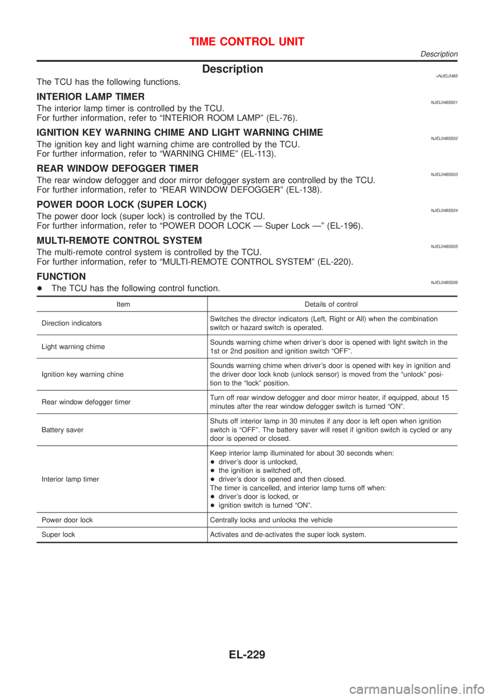
Description=NJEL0485The TCU has the following functions.
INTERIOR LAMP TIMERNJEL0485S01The interior lamp timer is controlled by the TCU.
For further information, refer to ªINTERIOR ROOM LAMPº (EL-76).
IGNITION KEY WARNING CHIME AND LIGHT WARNING CHIMENJEL0485S02The ignition key and light warning chime are controlled by the TCU.
For further information, refer to ªWARNING CHIMEº (EL-113).
REAR WINDOW DEFOGGER TIMERNJEL0485S03The rear window defogger and door mirror defogger system are controlled by the TCU.
For further information, refer to ªREAR WINDOW DEFOGGERº (EL-138).
POWER DOOR LOCK (SUPER LOCK)NJEL0485S04The power door lock (super lock) is controlled by the TCU.
For further information, refer to ªPOWER DOOR LOCK Ð Super Lock к (EL-196).
MULTI-REMOTE CONTROL SYSTEMNJEL0485S05The multi-remote control system is controlled by the TCU.
For further information, refer to ªMULTI-REMOTE CONTROL SYSTEMº (EL-220).
FUNCTIONNJEL0485S06+The TCU has the following control function.
Item Details of control
Direction indicatorsSwitches the director indicators (Left, Right or All) when the combination
switch or hazard switch is operated.
Light warning chimeSounds warning chime when driver's door is opened with light switch in the
1st or 2nd position and ignition switch ªOFFº.
Ignition key warning chineSounds warning chime when driver's door is opened with key in ignition and
the driver door lock knob (unlock sensor) is moved from the ªunlockº posi-
tion to the ªlockº position.
Rear window defogger timerTurn off rear window defogger and door mirror heater, if equipped, about 15
minutes after the rear window defogger switch is turned ªONº.
Battery saverShuts off interior lamp in 30 minutes if any door is left open when ignition
switch is ªOFFº. The battery saver will reset if ignition switch is cycled or any
door is opened or closed.
Interior lamp timerKeep interior lamp illuminated for about 30 seconds when:
+driver's door is unlocked,
+the ignition is switched off,
+driver's door is opened and then closed.
The timer is cancelled, and interior lamp turns off when:
+driver's door is locked, or
+ignition switch is turned ªONº.
Power door lock Centrally locks and unlocks the vehicle
Super lock Activates and de-activates the super lock system.
TIME CONTROL UNIT
Description
EL-229
Page 2343 of 2493
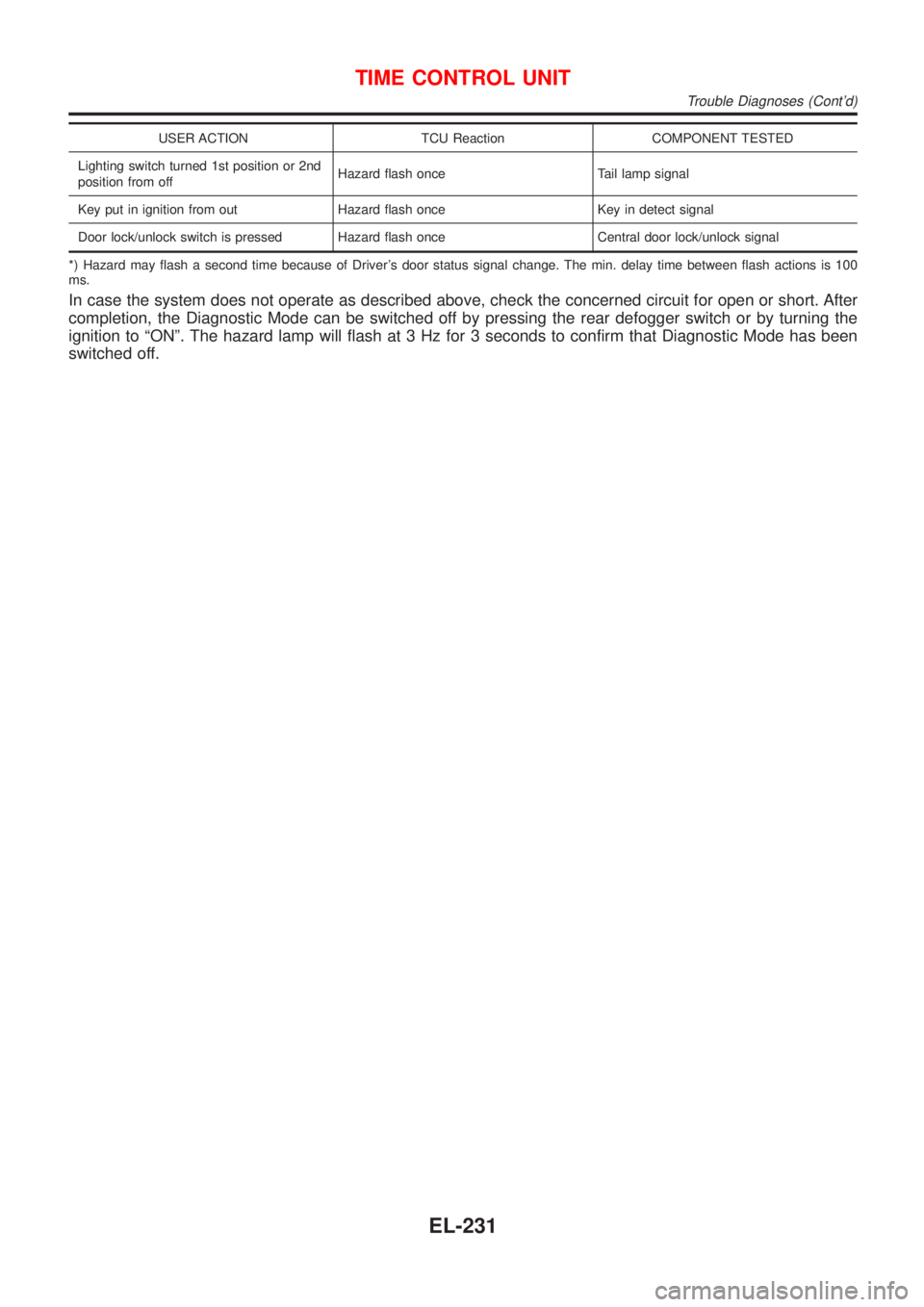
USER ACTION TCU Reaction COMPONENT TESTED
Lighting switch turned 1st position or 2nd
position from offHazard flash once Tail lamp signal
Key put in ignition from out Hazard flash once Key in detect signal
Door lock/unlock switch is pressed Hazard flash once Central door lock/unlock signal
*) Hazard may flash a second time because of Driver's door status signal change. The min. delay time between flash actions is 100
ms.
In case the system does not operate as described above, check the concerned circuit for open or short. After
completion, the Diagnostic Mode can be switched off by pressing the rear defogger switch or by turning the
ignition to ªONº. The hazard lamp will flash at 3 Hz for 3 seconds to confirm that Diagnostic Mode has been
switched off.
TIME CONTROL UNIT
Trouble Diagnoses (Cont'd)
EL-231
Page 2346 of 2493
Component Parts and Harness Connetor
Location
NJEL0406For details, refer to ªELECTRICAL UNIT LOCATIONº (EL-319) and
ªHARNESS LAYOUTº (EL-324).
System DescriptionNJEL0407NATS (Nissan Anti-Theft System) has the following immobilizer functions:
+Since only NATS ignition keys, whose ID nos. have been registered into the ECM and IMMU of NATS,
allow the engine to run, operation of a stolen vehicle without a NATS registered key is prevented by NATS.
That is to say, NATS will immobilize the engine if someone tries to start it without the registered key of
NATS.
+This version of NATS has dongle unit to improve its anti-theft performance (RHD models for Europe).
Dongle unit has its own ID which is registered into NATS IMMU. So if dongle unit is replaced, initialization
must be carried out.
+When malfunction of dongle unit is detected:
The security indicator lamp illuminates for about 15 minutes after ignition switch is turned to ON.
þ When dongle unit has a malfunction and the indicator lamp is illuminated, engine can not be started.
However engine can be started only one time when security indicator lamp turns off in about 15 minutes
after ignition switch is turned to ON.
+All of the originally supplied ignition key IDs have been NATS registered.
If requested by the vehicle owner, a maximum of five key IDs can be registered into the NATS compo-
nents.
+The security indicator blinks when the ignition switch is in ªOFFº or ªACCº position. Therefore, NATS warns
outsiders that the vehicle is equipped with the anti-theft system.
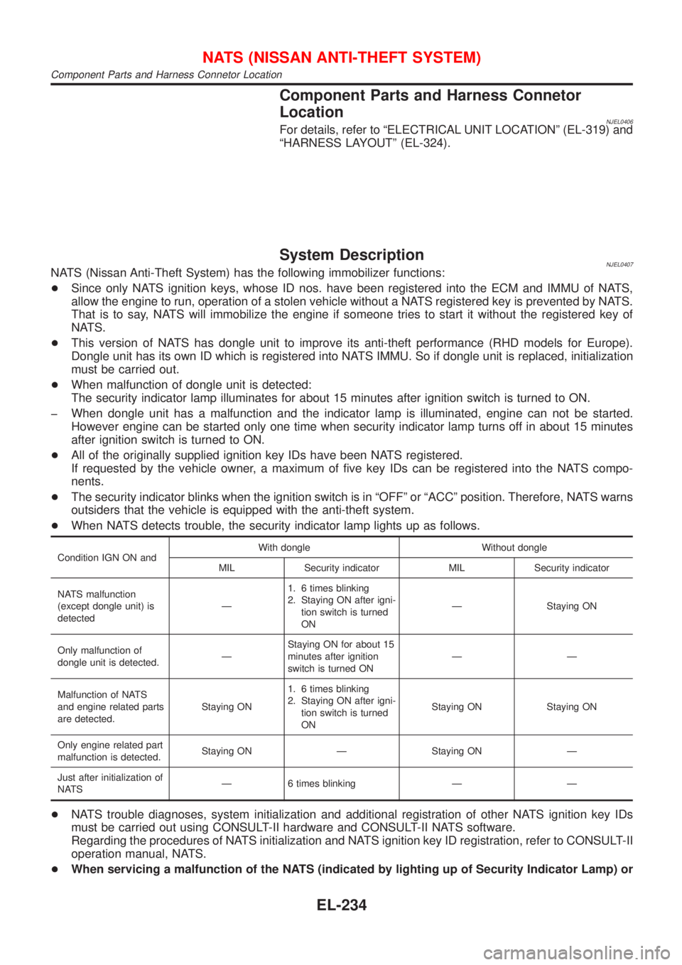
+When NATS detects trouble, the security indicator lamp lights up as follows.
Condition IGN ON andWith dongle Without dongle
MIL Security indicator MIL Security indicator
NATS malfunction
(except dongle unit) is
detectedÐ1. 6 times blinking
2. Staying ON after igni-
tion switch is turned
ONÐ Staying ON
Only malfunction of
dongle unit is detected.ÐStaying ON for about 15
minutes after ignition
switch is turned ONÐÐ
Malfunction of NATS
and engine related parts
are detected.Staying ON1. 6 times blinking
2. Staying ON after igni-
tion switch is turned
ONStaying ON Staying ON
Only engine related part
malfunction is detected.Staying ON Ð Staying ON Ð
Just after initialization of
NATSÐ 6 times blinking Ð Ð
+NATS trouble diagnoses, system initialization and additional registration of other NATS ignition key IDs
must be carried out using CONSULT-II hardware and CONSULT-II NATS software.
Regarding the procedures of NATS initialization and NATS ignition key ID registration, refer to CONSULT-II
operation manual, NATS.
+When servicing a malfunction of the NATS (indicated by lighting up of Security Indicator Lamp) or
NATS (NISSAN ANTI-THEFT SYSTEM)
Component Parts and Harness Connetor Location
EL-234
Page 2376 of 2493
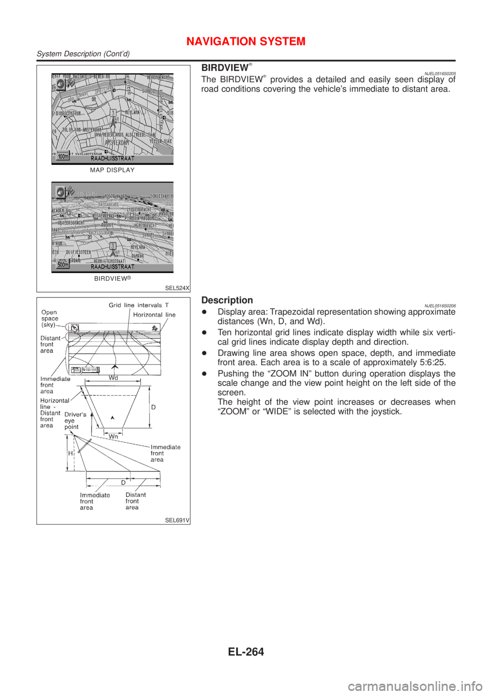
MAP DISPLAY
BIRDVIEW
R
SEL524X
BIRDVIEWTNJEL0516S0205The BIRDVIEWTprovides a detailed and easily seen display of
road conditions covering the vehicle's immediate to distant area.
SEL691V
DescriptionNJEL0516S0206+Display area: Trapezoidal representation showing approximate
distances (Wn, D, and Wd).
+Ten horizontal grid lines indicate display width while six verti-
cal grid lines indicate display depth and direction.
+Drawing line area shows open space, depth, and immediate
front area. Each area is to a scale of approximately 5:6:25.
+Pushing the ªZOOM INº button during operation displays the
scale change and the view point height on the left side of the
screen.
The height of the view point increases or decreases when
ªZOOMº or ªWIDEº is selected with the joystick.
NAVIGATION SYSTEM
System Description (Cont'd)
EL-264
Page 2391 of 2493
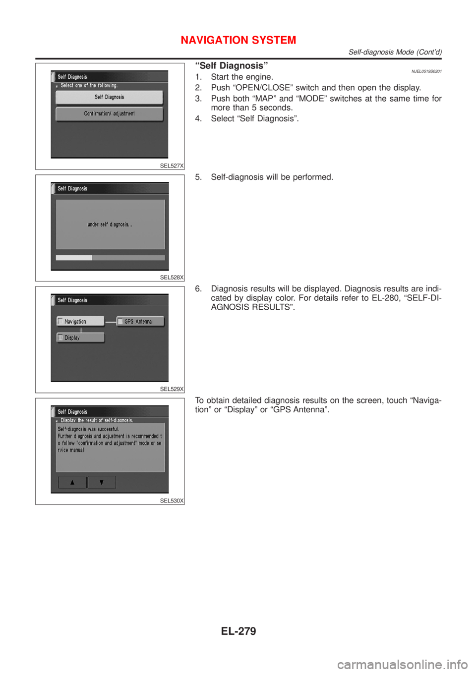
SEL527X
ªSelf DiagnosisºNJEL0519S02011. Start the engine.
2. Push ªOPEN/CLOSEº switch and then open the display.
3. Push both ªMAPº and ªMODEº switches at the same time for
more than 5 seconds.
4. Select ªSelf Diagnosisº.
SEL528X
5. Self-diagnosis will be performed.
SEL529X
6. Diagnosis results will be displayed. Diagnosis results are indi-
cated by display color. For details refer to EL-280, ªSELF-DI-
AGNOSIS RESULTSº.
SEL530X
To obtain detailed diagnosis results on the screen, touch ªNaviga-
tionº or ªDisplayº or ªGPS Antennaº.
NAVIGATION SYSTEM
Self-diagnosis Mode (Cont'd)
EL-279
Page 2392 of 2493
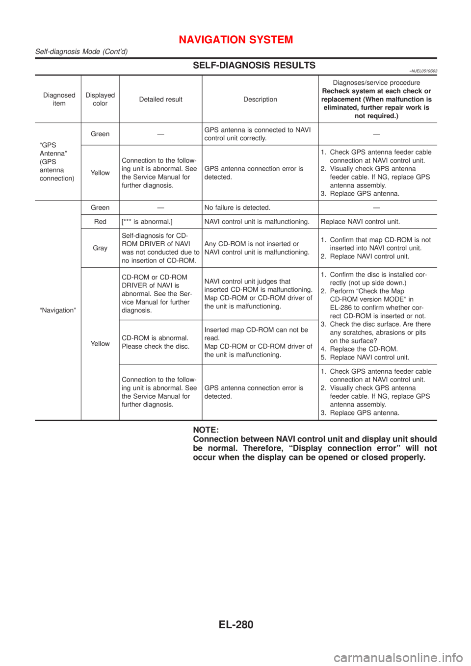
SELF-DIAGNOSIS RESULTS=NJEL0519S03
Diagnosed
itemDisplayed
colorDetailed result DescriptionDiagnoses/service procedure
Recheck system at each check or
replacement (When malfunction is
eliminated, further repair work is
not required.)
ªGPS
Antennaº
(GPS
antenna
connection)Green ÐGPS antenna is connected to NAVI
control unit correctly.Ð
YellowConnection to the follow-
ing unit is abnormal. See
the Service Manual for
further diagnosis.GPS antenna connection error is
detected.1. Check GPS antenna feeder cable
connection at NAVI control unit.
2. Visually check GPS antenna
feeder cable. If NG, replace GPS
antenna assembly.
3. Replace GPS antenna.
ªNavigationºGreen Ð No failure is detected. Ð
Red [*** is abnormal.] NAVI control unit is malfunctioning. Replace NAVI control unit.
GraySelf-diagnosis for CD-
ROM DRIVER of NAVI
was not conducted due to
no insertion of CD-ROM.Any CD-ROM is not inserted or
NAVI control unit is malfunctioning.1. Confirm that map CD-ROM is not
inserted into NAVI control unit.
2. Replace NAVI control unit.
YellowCD-ROM or CD-ROM
DRIVER of NAVI is
abnormal. See the Ser-
vice Manual for further
diagnosis.NAVI control unit judges that
inserted CD-ROM is malfunctioning.
Map CD-ROM or CD-ROM driver of
the unit is malfunctioning.1. Confirm the disc is installed cor-
rectly (not up side down.)
2. Perform ªCheck the Map
CD-ROM version MODEº in
EL-286 to confirm whether cor-
rect CD-ROM is inserted or not.
3. Check the disc surface. Are there
any scratches, abrasions or pits
on the surface?
4. Replace the CD-ROM.
5. Replace NAVI control unit. CD-ROM is abnormal.
Please check the disc.Inserted map CD-ROM can not be
read.
Map CD-ROM or CD-ROM driver of
the unit is malfunctioning.
Connection to the follow-
ing unit is abnormal. See
the Service Manual for
further diagnosis.GPS antenna connection error is
detected.1. Check GPS antenna feeder cable
connection at NAVI control unit.
2. Visually check GPS antenna
feeder cable. If NG, replace GPS
antenna assembly.
3. Replace GPS antenna.
NOTE:
Connection between NAVI control unit and display unit should
be normal. Therefore, ªDisplay connection errorº will not
occur when the display can be opened or closed properly.
NAVIGATION SYSTEM
Self-diagnosis Mode (Cont'd)
EL-280
Page 2421 of 2493
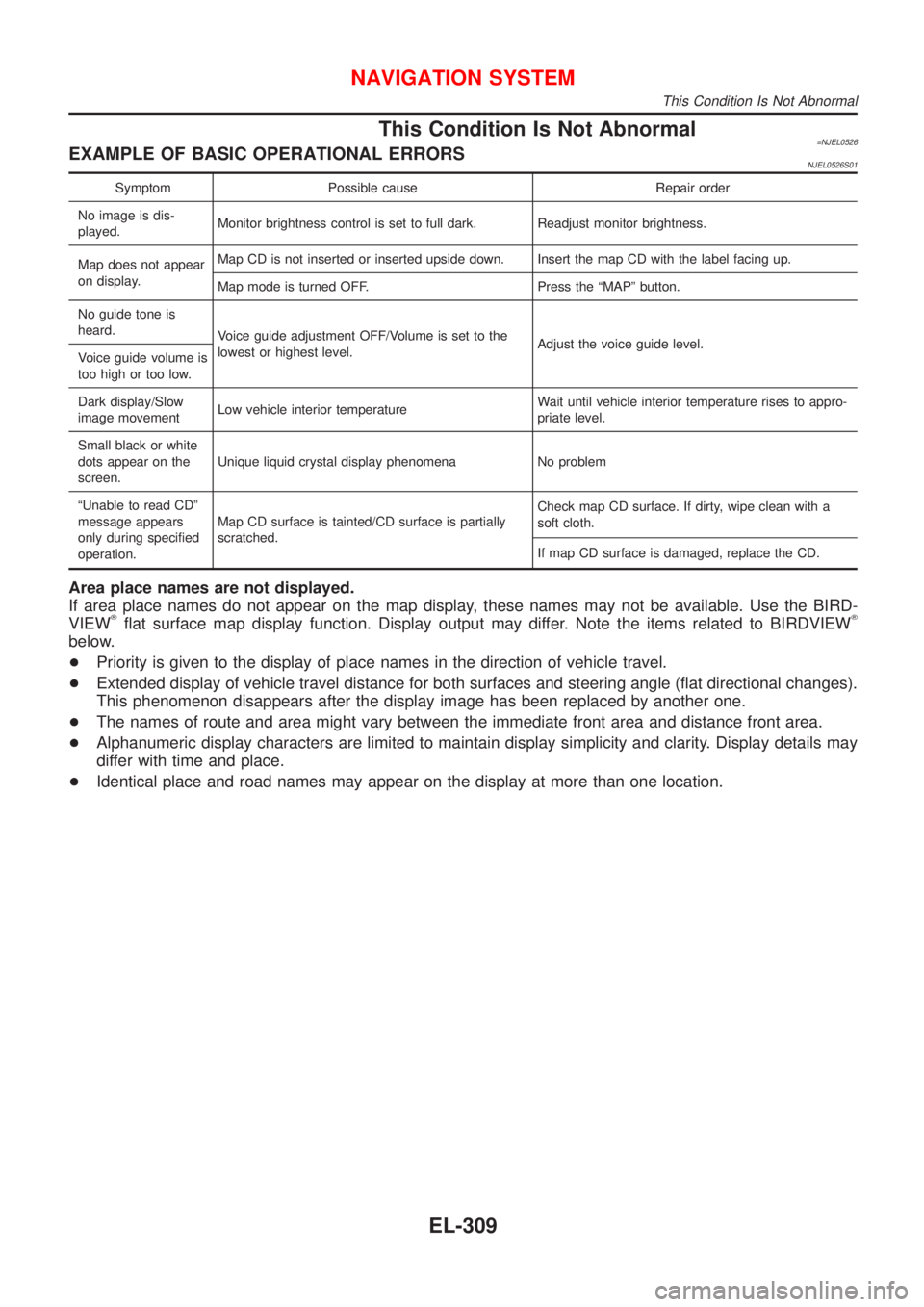
This Condition Is Not Abnormal=NJEL0526EXAMPLE OF BASIC OPERATIONAL ERRORSNJEL0526S01
Symptom Possible cause Repair order
No image is dis-
played.Monitor brightness control is set to full dark. Readjust monitor brightness.
Map does not appear
on display.Map CD is not inserted or inserted upside down. Insert the map CD with the label facing up.
Map mode is turned OFF. Press the ªMAPº button.
No guide tone is
heard.
Voice guide adjustment OFF/Volume is set to the
lowest or highest level.Adjust the voice guide level.
Voice guide volume is
too high or too low.
Dark display/Slow
image movementLow vehicle interior temperatureWait until vehicle interior temperature rises to appro-
priate level.
Small black or white
dots appear on the
screen.Unique liquid crystal display phenomena No problem
ªUnable to read CDº
message appears
only during specified
operation.Map CD surface is tainted/CD surface is partially
scratched.Check map CD surface. If dirty, wipe clean with a
soft cloth.
If map CD surface is damaged, replace the CD.
Area place names are not displayed.
If area place names do not appear on the map display, these names may not be available. Use the BIRD-
VIEW
Tflat surface map display function. Display output may differ. Note the items related to BIRDVIEWT
below.
+Priority is given to the display of place names in the direction of vehicle travel.
+Extended display of vehicle travel distance for both surfaces and steering angle (flat directional changes).
This phenomenon disappears after the display image has been replaced by another one.
+The names of route and area might vary between the immediate front area and distance front area.
+Alphanumeric display characters are limited to maintain display simplicity and clarity. Display details may
differ with time and place.
+Identical place and road names may appear on the display at more than one location.
NAVIGATION SYSTEM
This Condition Is Not Abnormal
EL-309
Page 2424 of 2493
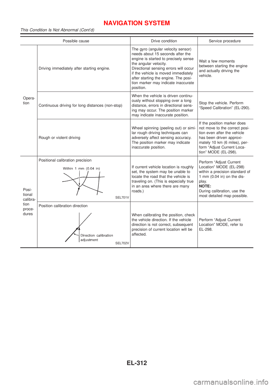
Possible cause Drive condition Service procedure
Opera-
tionDriving immediately after starting engine.The gyro (angular velocity sensor)
needs about 15 seconds after the
engine is started to precisely sense
the angular velocity.
Directional sensing errors will occur
if the vehicle is moved immediately
after starting the engine. The posi-
tion marker may indicate inaccurate
position.Wait a few moments
between starting the engine
and actually driving the
vehicle.
Continuous driving for long distances (non-stop)When the vehicle is driven continu-
ously without stopping over a long
distance, errors in directional sens-
ing may occur. The position marker
may indicate inaccurate position.Stop the vehicle. Perform
ªSpeed Calibrationº (EL-290).
Rough or violent drivingWheel spinning (peeling out) or simi-
lar rough driving techniques can
adversely affect sensing accuracy.
The position marker may indicate
inaccurate position.If the position marker does
not move to the correct posi-
tion even after the vehicle
has been driven approxi-
mately 10 km (6 miles), per-
form ªAdjust Current Loca-
tionº MODE (EL-298).
Posi-
tional
calibra-
tion
proce-
duresPositional calibration precision
SEL701V
If current vehicle location is roughly
set, the system may be unable to
locate the road that the vehicle is
traveling on. (This is especially true
in an area where there are many
roads.)Perform ªAdjust Current
Locationº MODE (EL-298)
within a precision standard of
1 mm (0.04 in) on the dis-
play.
NOTE:
During calibration, use the
most detailed map possible.
Position calibration direction
SEL702V
When calibrating the position, check
the vehicle direction. If the vehicle
direction is not correct, subsequent
precision of current location will be
affected.Perform ªAdjust Current
Locationº MODE, refer to
EL-298.
NAVIGATION SYSTEM
This Condition Is Not Abnormal (Cont'd)
EL-312