Page 430 of 2493
![NISSAN ALMERA N16 2001 Electronic Repair Manual TERMI-
NAL
NO.WIRE
COLORITEM CONDITION DATA (DC Voltage)
3 W/RHeated oxygen sensor 2
heater (rear)[Engine is running]
+Engine speed is below 3,600 rpm
+After driving for 2 minutes at a speed of 70
km/](/manual-img/5/57351/w960_57351-429.png "NISSAN ALMERA N16 2001 Electronic Repair Manual TERMI-
NAL
NO.WIRE
COLORITEM CONDITION DATA (DC Voltage)
3 W/RHeated oxygen sensor 2
heater (rear)[Engine is running]
+Engine speed is below 3,600 rpm
+After driving for 2 minutes at a speed of 70
km/")
TERMI-
NAL
NO.WIRE
COLORITEM CONDITION DATA (DC Voltage)
3 W/RHeated oxygen sensor 2
heater (rear)[Engine is running]
+Engine speed is below 3,600 rpm
+After driving for 2 minutes at a speed of 70
km/h (43 MPH) or moreApproximately 0.7V
[Ignition switch ªONº]
+Engine stopped
+Engine speed is above 3,600 rpmBATTERY VOLTAGE
(11 - 14V)
4 R/BHeated oxygen sensor 1
heater (front)[Engine is running]
+Engine speed is below 3,200 rpmApproximately 0V
[Engine is running]
+Engine speed is above 3,200 rpmBATTERY VOLTAGE
(11 - 14V)
6
7
15
16BR
L/G
P
ORIACV-AAC valve[Engine is running]
+Warm-up condition
+Idle speed0.1 - 14V
8*
9*
17*
18*SB
W/B
R/Y
BR/REGR volume control
valve[Engine is running]
+Warm-up condition
+Rev engine from 2,000 to 4,000 rpm0 - 14V
10 Y/B A/T signal No. 3[Engine is running]
+Idle speedApproximately 0V
13 LG/R Cooling fan relay[Engine is running]
+Cooling fan is not operatingBATTERY VOLTAGE
(11 - 14V)
[Engine is running]
+Cooling fan is operatingApproximately 0V
14 GY/LEVAP canister purge
volume control valve
(ON/OFF duty)[Engine is running]
+Warm-up condition
+Accelerator pedal depressed5 - 12V
SEF975W
19 BR/W A/T signal No. 5[Engine is running]
+Idle speedApproximately 8V
21 B/P Fuel pump relay[Ignition switch ªONº]
+For 1 second after turning ignition switch
ªONº
[Engine is running]0-1V
[Ignition switch ªONº]
+More than 1 second after turning ignition
switch ªONºBATTERY VOLTAGE
(11 - 14V)
22 OR/L Malfunction indicator[Ignition switch ªONº]0-1V
[Engine is running]
+Idle speedBATTERY VOLTAGE
(11 - 14V)
23 L Air conditioner relay[Engine is running]
+Both A/C switch and blower switch are ªONºApproximately 0V
[Engine is running]
+A/C switch is ªOFFºBATTERY VOLTAGE
(11 - 14V)
TROUBLE DIAGNOSIS Ð GENERAL DESCRIPTIONQG
ECM Terminals and Reference Value (Cont'd)
EC-134
Page 548 of 2493

4 CHECK FUEL PRESSURE
1. Release fuel pressure to zero.
Refer to EC-38.
2. Install fuel pressure gauge and check fuel pressure.
At idling:
When fuel pressure regulator valve vacuum hose is connected.
235 kPa (2.35 bar, 2.4 kg/cm
2, 34 psi)
When fuel pressure regulator valve vacuum hose is disconnected.
294 kPa (2.94 bar, 3.0 kg/cm
2, 43 psi)
OK or NG
OK©GO TO 6.
NG©GO TO 5.
5 DETECT MALFUNCTIONING PART
Check the following.
+Fuel pump and circuit (Refer to EC-464.)
+Fuel pressure regulator (Refer to EC-39.)
+Fuel lines (Refer to ªENGINE MAINTENANCEº in MA section.)
+Fuel filter for clogging
©Repair or replace.
6 CHECK MASS AIR FLOW SENSOR
With CONSULT-II
Check ªMASS AIR FLOWº in ªDATA MONITORº mode with CONSULT-II.
at idling: 1.0 - 4.0 g´m/sec
at 2,500 rpm: 5.0 - 10.0 g´m/sec
With GST
Check mass air flow sensor signal in MODE 1 with GST.
at idling: 1.0 - 4.0 g´m/sec
at 2,500 rpm: 5.0 - 10.0 g´m/sec
OK or NG
OK©GO TO 7.
NG©Check connectors for rusted terminals or loose connections in the mass air flow sensor
circuit or engine grounds. Refer to EC-152.
DTC P0171 FUEL INJECTION SYSTEM FUNCTION (LEAN SIDE)QG
Diagnostic Procedure (Cont'd)
EC-252
Page 555 of 2493
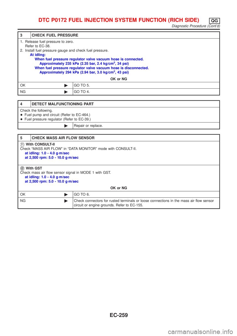
3 CHECK FUEL PRESSURE
1. Release fuel pressure to zero.
Refer to EC-38.
2. Install fuel pressure gauge and check fuel pressure.
At idling:
When fuel pressure regulator valve vacuum hose is connected.
Approximately 235 kPa (2.35 bar, 2.4 kg/cm
2, 34 psi)
When fuel pressure regulator valve vacuum hose is disconnected.
Approximately 294 kPa (2.94 bar, 3.0 kg/cm
2, 43 psi)
OK or NG
OK©GO TO 5.
NG©GO TO 4.
4 DETECT MALFUNCTIONING PART
Check the following.
+Fuel pump and circuit (Refer to EC-464.)
+Fuel pressure regulator (Refer to EC-39.)
©Repair or replace.
5 CHECK MASS AIR FLOW SENSOR
With CONSULT-II
Check ªMASS AIR FLOWº in ªDATA MONITORº mode with CONSULT-II.
at idling: 1.0 - 4.0 g´m/sec
at 2,500 rpm: 5.0 - 10.0 g´m/sec
With GST
Check mass air flow sensor signal in MODE 1 with GST.
at idling: 1.0 - 4.0 g´m/sec
at 2,500 rpm: 5.0 - 10.0 g´m/sec
OK or NG
OK©GO TO 6.
NG©Check connectors for rusted terminals or loose connections in the mass air flow sensor
circuit or engine grounds. Refer to EC-155.
DTC P0172 FUEL INJECTION SYSTEM FUNCTION (RICH SIDE)QG
Diagnostic Procedure (Cont'd)
EC-259
Page 562 of 2493
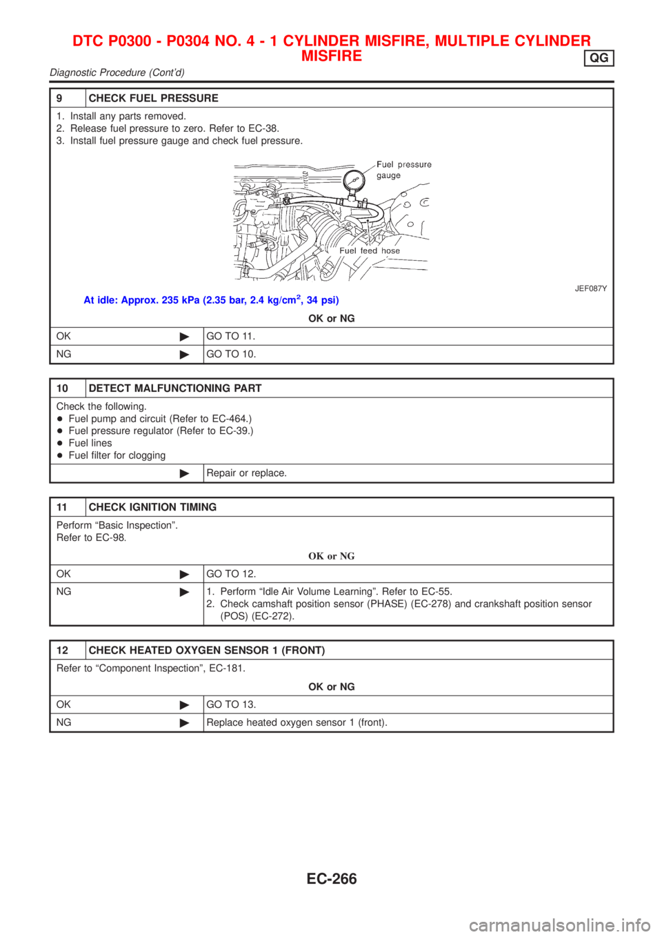
9 CHECK FUEL PRESSURE
1. Install any parts removed.
2. Release fuel pressure to zero. Refer to EC-38.
3. Install fuel pressure gauge and check fuel pressure.
JEF087Y
At idle: Approx. 235 kPa (2.35 bar, 2.4 kg/cm2, 34 psi)
OK or NG
OK©GO TO 11.
NG©GO TO 10.
10 DETECT MALFUNCTIONING PART
Check the following.
+Fuel pump and circuit (Refer to EC-464.)
+Fuel pressure regulator (Refer to EC-39.)
+Fuel lines
+Fuel filter for clogging
©Repair or replace.
11 CHECK IGNITION TIMING
Perform ªBasic Inspectionº.
Refer to EC-98.
OK or NG
OK©GO TO 12.
NG©1. Perform ªIdle Air Volume Learningº. Refer to EC-55.
2. Check camshaft position sensor (PHASE) (EC-278) and crankshaft position sensor
(POS) (EC-272).
12 CHECK HEATED OXYGEN SENSOR 1 (FRONT)
Refer to ªComponent Inspectionº, EC-181.
OK or NG
OK©GO TO 13.
NG©Replace heated oxygen sensor 1 (front).
DTC P0300 - P0304 NO.4-1CYLINDER MISFIRE, MULTIPLE CYLINDER
MISFIRE
QG
Diagnostic Procedure (Cont'd)
EC-266
Page 760 of 2493

System DescriptionNJEC0444
Sensor Input Signal to ECMECM func-
tionActuator
Crankshaft position sensor (POS) Engine speed
Fuel pump
controlFuel pump relay Camshaft position sensor (PHASE) Engine speed and cylinder number
Ignition switch Ignition signal and start signal
The ECM activates the fuel pump for several seconds after the ignition switch is turned on to improve engine
startability. If the ECM receives a 180É signal from the camshaft position sensor, it knows that the engine is
rotating, and causes the pump to perform. If the 180É signal is not received when the ignition switch is on, the
engine stalls. The ECM stops pump operation and prevents battery discharging, thereby improving safety. The
ECM does not directly drive the fuel pump. It controls the ON/OFF fuel pump relay, which in turn controls the
fuel pump.
Condition Fuel pump operation
Ignition switch is turned to ON. Operates for 1 second
Engine running and cranking Operates
When engine is stopped (Signal is not sent from crankshaft position sensor
and camshaft position sensor.)Stops in 1.5 seconds
Except as shown aboveStops
SEF605X
Component DescriptionNJEC0501A turbine type design fuel pump is used in the fuel tank.
CONSULT-II Reference Value in Data Monitor
Mode
NJEC0445
MONITOR ITEM CONDITION SPECIFICATION
FUEL PUMP RLY+Ignition switch is turned to ON (Operates for 1 second)
+Engine running and cranking
+When engine is stopped (stops in 1.5 seconds)ON
+Except as shown above OFF
FUEL PUMPQG
System Description
EC-464
Page 761 of 2493
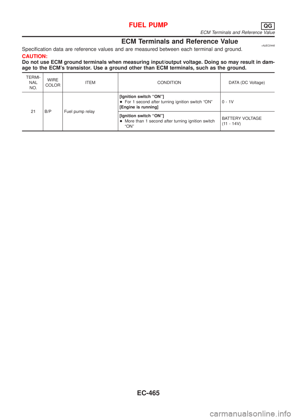
ECM Terminals and Reference Value=NJEC0446Specification data are reference values and are measured between each terminal and ground.
CAUTION:
Do not use ECM ground terminals when measuring input/output voltage. Doing so may result in dam-
age to the ECM's transistor. Use a ground other than ECM terminals, such as the ground.
TERMI-
NAL
NO.WIRE
COLORITEM CONDITION DATA (DC Voltage)
21 B/P Fuel pump relay[Ignition switch ªONº]
+For 1 second after turning ignition switch ªONº
[Engine is running]0-1V
[Ignition switch ªONº]
+More than 1 second after turning ignition switch
ªONºBATTERY VOLTAGE
(11 - 14V)
FUEL PUMPQG
ECM Terminals and Reference Value
EC-465
Page 762 of 2493
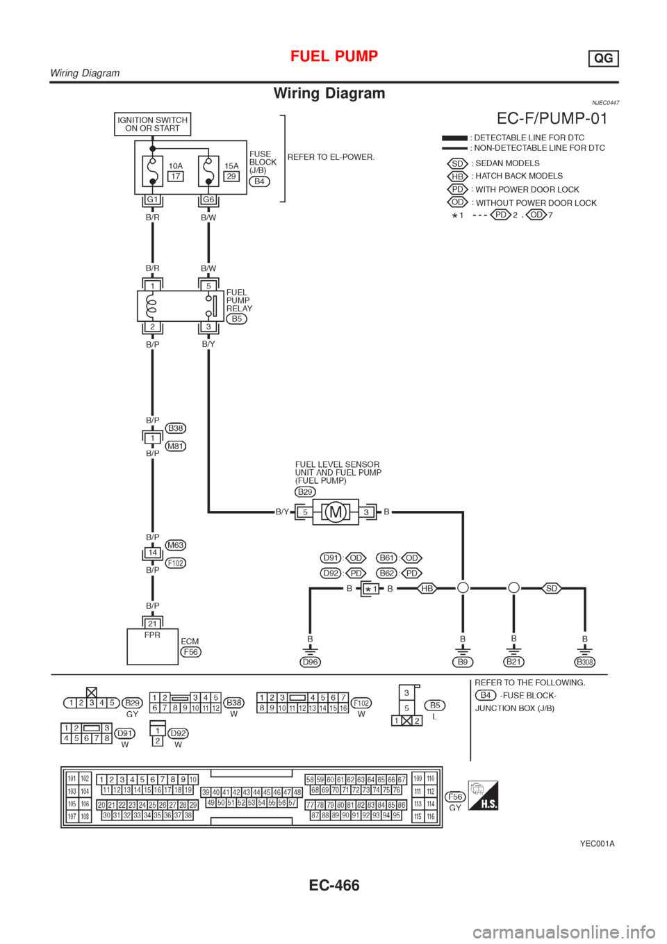
Wiring DiagramNJEC0447
YEC001A
FUEL PUMPQG
Wiring Diagram
EC-466
Page 763 of 2493
Diagnostic ProcedureNJEC0448
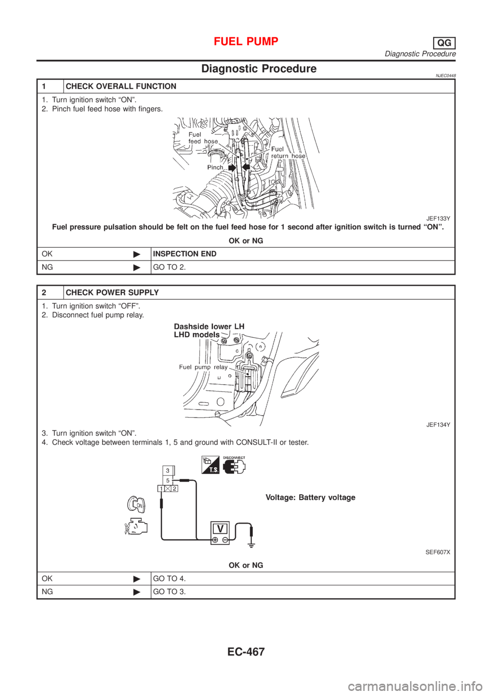
1 CHECK OVERALL FUNCTION
1. Turn ignition switch ªONº.
2. Pinch fuel feed hose with fingers.
JEF133Y
Fuel pressure pulsation should be felt on the fuel feed hose for 1 second after ignition switch is turned ªONº.
OK or NG
OK©INSPECTION END
NG©GO TO 2.
2 CHECK POWER SUPPLY
1. Turn ignition switch ªOFFº.
2. Disconnect fuel pump relay.
JEF134Y
3. Turn ignition switch ªONº.
4. Check voltage between terminals 1, 5 and ground with CONSULT-II or tester.
SEF607X
OK or NG
OK©GO TO 4.
NG©GO TO 3.
FUEL PUMPQG
Diagnostic Procedure
EC-467