Page 1132 of 2493
NJMT0067
SMT722DB
Clutch HousingNJMT0067S011. Hammer the striking rod oil seal into clutch housing as far as
it will go.
CAUTION:
Do not reuse striking rod oil seal.
SMT723DA
2. Hammer the differential oil seal into clutch housing until it
becomes flush with clutch housing end face.
CAUTION:
Do not reuse differential oil seal.
SMT724DA
3. Hammer input shaft oil seal into clutch housing as far as it will
go.
CAUTION:
Do not reuse input shaft oil seal.
SMT725DB
4. Hammer the dust seal into clutch housing as far as it will go.
CAUTION:
Do not reuse dust seal.
SMT726DB
5. Install outer race of differential side bearing.
ASSEMBLYRS5F70A
Clutch Housing
MT-82
Page 1135 of 2493

SMT736D
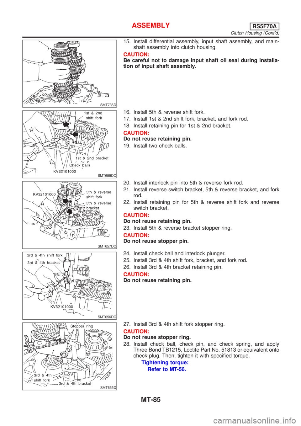
15. Install differential assembly, input shaft assembly, and main-
shaft assembly into clutch housing.
CAUTION:
Be careful not to damage input shaft oil seal during installa-
tion of input shaft assembly.
SMT659DC
16. Install 5th & reverse shift fork.
17. Install 1st & 2nd shift fork, bracket, and fork rod.
18. Install retaining pin for 1st & 2nd bracket.
CAUTION:
Do not reuse retaining pin.
19. Install two check balls.
SMT657DC
20. Install interlock pin into 5th & reverse fork rod.
21. Install reverse switch bracket, 5th & reverse bracket, and fork
rod.
22. Install retaining pin for 5th & reverse shift fork and reverse
switch bracket.
CAUTION:
Do not reuse retaining pin.
23. Install 5th & reverse bracket stopper ring.
CAUTION:
Do not reuse stopper pin.
SMT656DC
24. Install check ball and interlock plunger.
25. Install 3rd & 4th shift fork, bracket, and fork rod.
26. Install 3rd & 4th bracket retaining pin.
CAUTION:
Do not reuse retaining pin.
SMT655D
27. Install 3rd & 4th shift fork stopper ring.
CAUTION:
Do not reuse stopper ring.
28. Install check ball, check pin, and check spring, and apply
Three Bond TB1215, Loctite Part No. 51813 or equivalent onto
check plug. Then, tighten it with specified torque.
Tightening torque:
Refer to MT-56.
ASSEMBLYRS5F70A
Clutch Housing (Cont'd)
MT-85
Page 1136 of 2493
SMT737DA
Transaxle CaseNJMT0067S021. Insert differential oil seal into differential case until it becomes
flush with case end face.
SMT739D
2. Install welch plug into transaxle case.
SMT740D
3. Calculate dimension ªNº (thickness of adjusting shim) using
the following procedure to satisfy specification of end play for
differential side bearing.
End play: 0.15 - 0.21 mm (0.0059 - 0.0083 in)
Dimension ªNº = (N1 ± N2) + End play
N: Thickness of adjusting shim
N1: Distance between clutch housing case end
face and mounting face of adjusting shim
N2: Distance between differential side bearing and
transaxle case
Differential side bearing adjusting shims:
Refer to SDS, MT-131.
SMT741D
a. Using dial gauge and scale, measure dimension ªN1º between
clutch housing case end face and mounting face of adjusting
shim.
ASSEMBLYRS5F70A
Transaxle Case
MT-86
Page 1137 of 2493

SMT742D
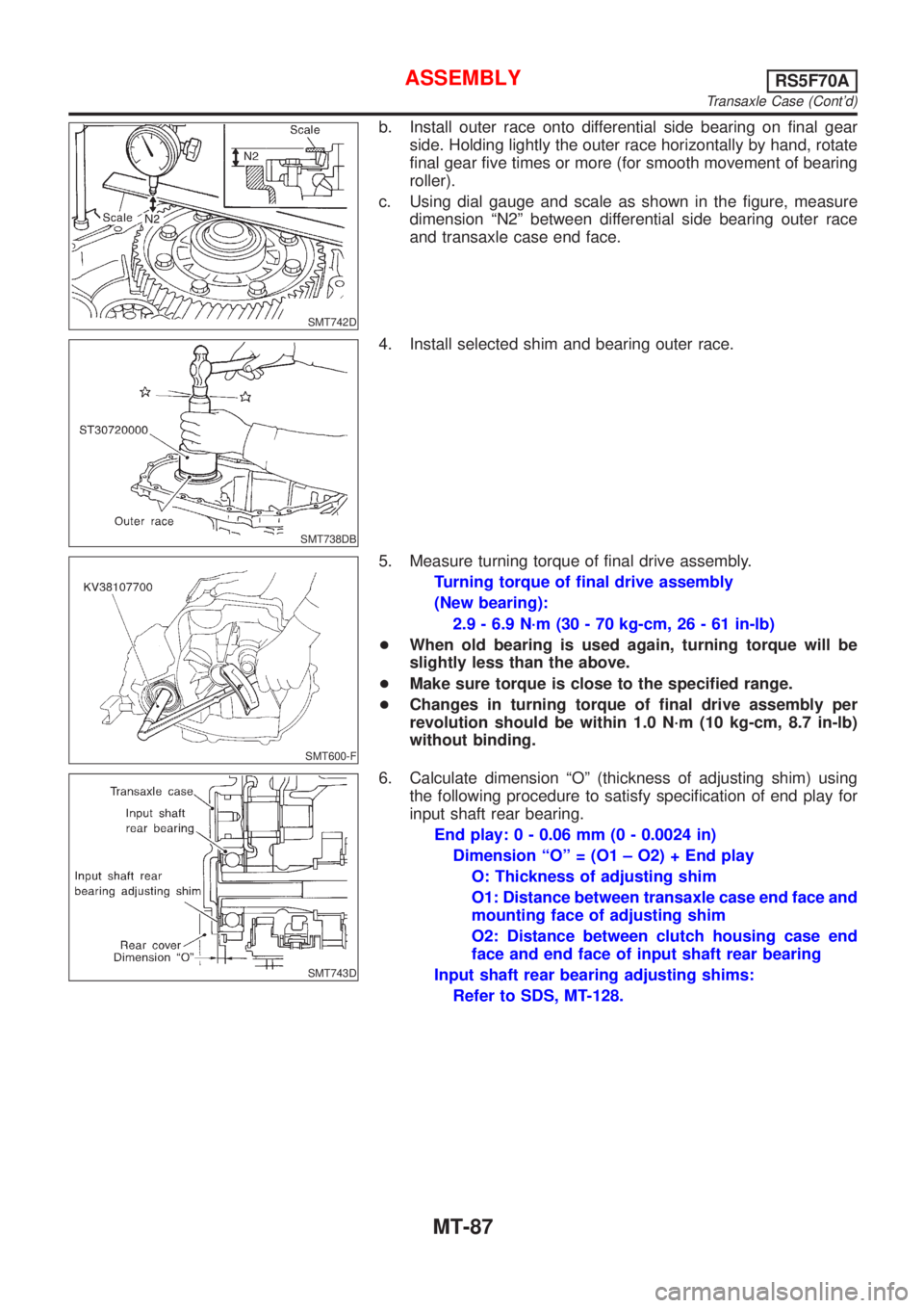
b. Install outer race onto differential side bearing on final gear
side. Holding lightly the outer race horizontally by hand, rotate
final gear five times or more (for smooth movement of bearing
roller).
c. Using dial gauge and scale as shown in the figure, measure
dimension ªN2º between differential side bearing outer race
and transaxle case end face.
SMT738DB
4. Install selected shim and bearing outer race.
SMT600-F
5. Measure turning torque of final drive assembly.
Turning torque of final drive assembly
(New bearing):
2.9 - 6.9 N´m (30 - 70 kg-cm, 26 - 61 in-lb)
+When old bearing is used again, turning torque will be
slightly less than the above.
+Make sure torque is close to the specified range.
+Changes in turning torque of final drive assembly per
revolution should be within 1.0 N´m (10 kg-cm, 8.7 in-lb)
without binding.
SMT743D
6. Calculate dimension ªOº (thickness of adjusting shim) using
the following procedure to satisfy specification of end play for
input shaft rear bearing.
End play: 0 - 0.06 mm (0 - 0.0024 in)
Dimension ªOº = (O1 ± O2) + End play
O: Thickness of adjusting shim
O1: Distance between transaxle case end face and
mounting face of adjusting shim
O2: Distance between clutch housing case end
face and end face of input shaft rear bearing
Input shaft rear bearing adjusting shims:
Refer to SDS, MT-128.
ASSEMBLYRS5F70A
Transaxle Case (Cont'd)
MT-87
Page 1142 of 2493
NJMT0009
Case ComponentsNJMT0009S02
SMT943D
1. Speedometer pinion
2. Differential oil seal
3. Drain plug
4. Boot
5. Striking rod oil seal
6. Magnet
7. Clutch housing8. Input shaft oil seal
9. Oil channel (Mainshaft)
10. Oil pocket
11. Oil gutter
12. Oil channel (Input shaft)
13. Transmission case14. Filler plug
15. O-ring
16. Movable plate assembly
17. PNP switch
18. Breather hose
19. Breather pipe
OVERHAULRS5F50A
Case Components
MT-92
Page 1143 of 2493

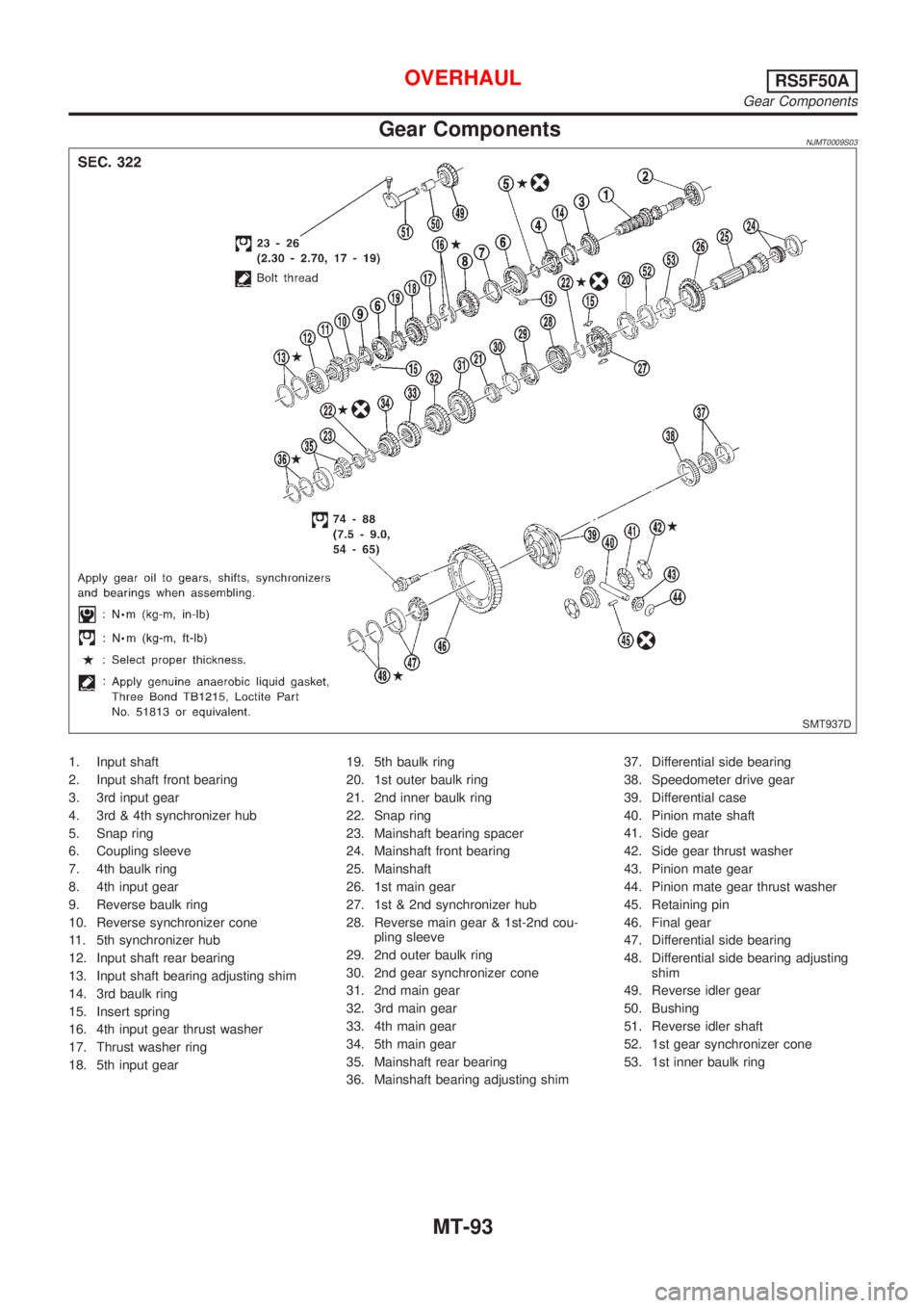
Gear ComponentsNJMT0009S03
SMT937D
1. Input shaft
2. Input shaft front bearing
3. 3rd input gear
4. 3rd & 4th synchronizer hub
5. Snap ring
6. Coupling sleeve
7. 4th baulk ring
8. 4th input gear
9. Reverse baulk ring
10. Reverse synchronizer cone
11. 5th synchronizer hub
12. Input shaft rear bearing
13. Input shaft bearing adjusting shim
14. 3rd baulk ring
15. Insert spring
16. 4th input gear thrust washer
17. Thrust washer ring
18. 5th input gear19. 5th baulk ring
20. 1st outer baulk ring
21. 2nd inner baulk ring
22. Snap ring
23. Mainshaft bearing spacer
24. Mainshaft front bearing
25. Mainshaft
26. 1st main gear
27. 1st & 2nd synchronizer hub
28. Reverse main gear & 1st-2nd cou-
pling sleeve
29. 2nd outer baulk ring
30. 2nd gear synchronizer cone
31. 2nd main gear
32. 3rd main gear
33. 4th main gear
34. 5th main gear
35. Mainshaft rear bearing
36. Mainshaft bearing adjusting shim37. Differential side bearing
38. Speedometer drive gear
39. Differential case
40. Pinion mate shaft
41. Side gear
42. Side gear thrust washer
43. Pinion mate gear
44. Pinion mate gear thrust washer
45. Retaining pin
46. Final gear
47. Differential side bearing
48. Differential side bearing adjusting
shim
49. Reverse idler gear
50. Bushing
51. Reverse idler shaft
52. 1st gear synchronizer cone
53. 1st inner baulk ring
OVERHAULRS5F50A
Gear Components
MT-93
Page 1157 of 2493
SMT059A
9. Press on thrust washer and press on mainshaft rear bearing.
10. Press on mainshaft front bearing.
11. Measure gear end play as a final check. Refer to
ªDISASSEMBLYº, MT-103.
SMT744AA
Final Drive
DISASSEMBLYNJMT00171. Remove final gear.
2. Remove speedometer drive gear by cutting it.
3. Press out differential side bearings.
+Be careful not to mix up the right and left bearings.
SMT612AA
4. Drive out retaining pin and draw out pinion mate shaft.
5. Remove pinion mate gears and side gears.
SMT083A
INSPECTIONNJMT0018Gear, Washer, Shaft and CaseNJMT0018S01+Check mating surfaces of differential case, viscous coupling,
side gears and pinion mate gears.
+Check washers for wear.
SPD715
BearingsNJMT0018S03+Make sure bearings roll freely and are free from noise, cracks,
pitting or wear.
+When replacing taper roller bearing, replace outer and
inner race as a set.
REPAIR FOR COMPONENT PARTSRS5F50A
Mainshaft and Gears (Cont'd)
MT-107
Page 1158 of 2493
SMT062A
ASSEMBLYNJMT00191. Attach side gear thrust washers to side gears, then install pin-
ion mate washers and pinion mate gears in place.
SMT087A
2. Insert pinion mate shaft.
+When inserting, be careful not to damage pinion mate
thrust washers.
SMT610AH
3. Measure clearance between side gear and differential case
with washers following the procedure below:
a. Set Tool and dial indicator on side gear.
b. Move side gear up and down to measure dial indicator deflec-
tion. Always measure indicator deflection on both side gears.
Clearance between side gear and differential case with
washers:
0.1 - 0.2 mm (0.004 - 0.008 in)
SMT611A
c. If not within specification, adjust clearance by changing thick-
ness of side gear thrust washers.
Differential side gear thrust washer:
Refer to SDS, MT-134.
SMT612AA
4. Install retaining pin.
+Make sure that retaining pin is flush with case.
REPAIR FOR COMPONENT PARTSRS5F50A
Final Drive (Cont'd)
MT-108