Page 1613 of 2493
SMT700B
7. Press on differential side bearings.
REPAIR FOR COMPONENT PARTS
Final Drive (Cont'd)
AT-427
Page 1614 of 2493
SAT311G
Assembly (1)NJAT01731. Install revolution sensor onto transmission case.
Always use new sealing parts.
SAT881I
2. Install differential side oil seals on transmission case and con-
verter housing, so that ªAº and ªBº are within specifications.
SAT027K
Unit: mm (in)
AB
5.5 - 6.5 (0.217 - 0.256) þ0.5 to 0.5 (þ0.020 to 0.020)
SAT328D
3. Install parking actuator support to transmission case.
+Pay attention to direction of parking actuator support.
SAT329D
4. Install parking pawl on transmission case and fix it with park-
ing shaft.
ASSEMBLY
Assembly (1)
AT-428
Page 1615 of 2493
SAT330D
5. Install return spring.
NAT059
Adjustment (1)NJAT0174DIFFERENTIAL SIDE BEARING PRELOADNJAT0174S011. Install differential side bearing outer race without adjusting
shim on transmission case.
2. Install differential side bearing outer race on converter housing.
SAT027D
3. Place final drive assembly on transmission case.
4. Install transmission case on converter housing. Tighten trans-
mission case fixing boltsAandBto the specified torque.
NAT060
5. Attach dial indicator on differential case at transmission case
side.
6. Insert Tool into differential side gear from converter housing.
7. Move Tool up and down and measure dial indicator deflection.
Differential side bearing preload ªTº:
0.04 - 0.09 mm (0.0016 - 0.0035 in)
8. Select proper thickness of differential side bearing adjusting
shim(s) using SDS table as a guide.
Differential side bearing adjusting shim:
Refer to SDS, AT-454.
ASSEMBLY
Assembly (1) (Cont'd)
AT-429
Page 1616 of 2493

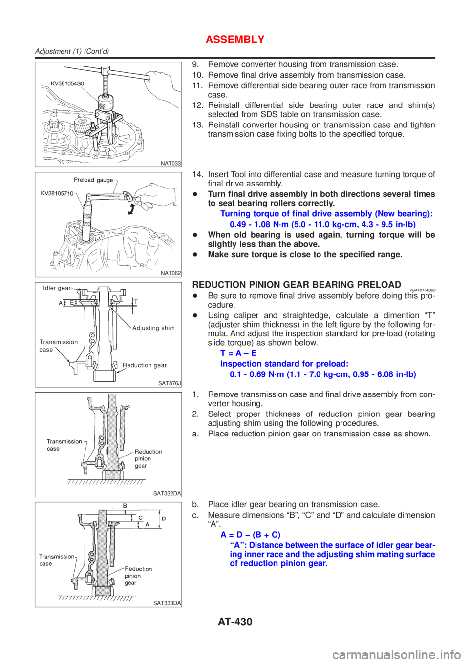
NAT033
9. Remove converter housing from transmission case.
10. Remove final drive assembly from transmission case.
11. Remove differential side bearing outer race from transmission
case.
12. Reinstall differential side bearing outer race and shim(s)
selected from SDS table on transmission case.
13. Reinstall converter housing on transmission case and tighten
transmission case fixing bolts to the specified torque.
NAT062
14. Insert Tool into differential case and measure turning torque of
final drive assembly.
+Turn final drive assembly in both directions several times
to seat bearing rollers correctly.
Turning torque of final drive assembly (New bearing):
0.49 - 1.08 N´m (5.0 - 11.0 kg-cm, 4.3 - 9.5 in-lb)
+When old bearing is used again, turning torque will be
slightly less than the above.
+Make sure torque is close to the specified range.
SAT876J
REDUCTION PINION GEAR BEARING PRELOADNJAT0174S02+Be sure to remove final drive assembly before doing this pro-
cedure.
+Using caliper and straightedge, calculate a dimention ªTº
(adjuster shim thickness) in the left figure by the following for-
mula. And adjust the inspection standard for pre-load (rotating
slide torque) as shown below.
T=A±E
Inspection standard for preload:
0.1 - 0.69 N´m (1.1 - 7.0 kg-cm, 0.95 - 6.08 in-lb)
SAT332DA
1. Remove transmission case and final drive assembly from con-
verter housing.
2. Select proper thickness of reduction pinion gear bearing
adjusting shim using the following procedures.
a. Place reduction pinion gear on transmission case as shown.
SAT333DA
b. Place idler gear bearing on transmission case.
c. Measure dimensions ªBº, ªCº and ªDº and calculate dimension
ªAº.
A=Dþ(B+C)
ªAº: Distance between the surface of idler gear bear-
ing inner race and the adjusting shim mating surface
of reduction pinion gear.
ASSEMBLY
Adjustment (1) (Cont'd)
AT-430
Page 1631 of 2493
SAT405D
3. Install O-ring on differential oil port of transmission case.
4. Install converter housing on transmission case.
+Apply locking sealant to mating surface of converter
housing.
Bolt Length mm (in)
A32.8 (1.291)
B40 (1.57)
SAT406DA
5. Install accumulator piston.
a. Check contact surface of accumulator piston for damage.
SAT407DA
b. Install O-rings on accumulator piston.
+Apply ATF to O-rings.
Accumulator piston O-rings:
Refer to SDS, AT-457.
SAT878J
c. Install accumulator pistons and return springs on transmission
case.
+Apply ATF to inner surface of transmission case.
Return springs:
Refer to SDS, AT-457.
ASSEMBLY
Assembly (4) (Cont'd)
AT-445
Page 1639 of 2493

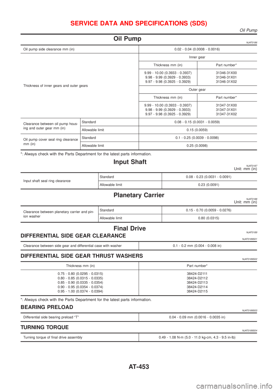
Oil PumpNJAT0186
Oil pump side clearance mm (in) 0.02 - 0.04 (0.0008 - 0.0016)
Thickness of inner gears and outer gearsInner gear
Thickness mm (in) Part number*
9.99 - 10.00 (0.3933 - 0.3937)
9.98 - 9.99 (0.3929 - 0.3933)
9.97 - 9.98 (0.3925 - 0.3929)31346-31X00
31346-31X01
31346-31X02
Outer gear
Thickness mm (in) Part number*
9.99 - 10.00 (0.3933 - 0.3937)
9.98 - 9.99 (0.3929 - 0.3933)
9.97 - 9.98 (0.3925 - 0.3929)31347-31X00
31347-31X01
31347-31X02
Clearance between oil pump hous-
ing and outer gear mm (in)Standard 0.08 - 0.15 (0.0031 - 0.0059)
Allowable limit 0.15 (0.0059)
Oil pump cover seal ring clearance
mm (in)Standard 0.1 - 0.25 (0.0039 - 0.0098)
Allowable limit 0.25 (0.0098)
*: Always check with the Parts Department for the latest parts information.
Input ShaftNJAT0187Unit: mm (in)
Input shaft seal ring clearanceStandard 0.08 - 0.23 (0.0031 - 0.0091)
Allowable limit 0.23 (0.0091)
Planetary CarrierNJAT0188Unit: mm (in)
Clearance between planetary carrier and pin-
ion washerStandard 0.15 - 0.70 (0.0059 - 0.0276)
Allowable limit 0.80 (0.0315)
Final DriveNJAT0189DIFFERENTIAL SIDE GEAR CLEARANCENJAT0189S01
Clearance between side gear and differential case with washer 0.1 - 0.2 mm (0.004 - 0.008 in)
DIFFERENTIAL SIDE GEAR THRUST WASHERSNJAT0189S02
Thickness mm (in) Part number*
0.75 - 0.80 (0.0295 - 0.0315)
0.80 - 0.85 (0.0315 - 0.0335)
0.85 - 0.90 (0.0335 - 0.0354)
0.90 - 0.95 (0.0354 - 0.0374)
0.95 - 1.00 (0.0374 - 0.0394)38424-D2111
38424-D2112
38424-D2113
38424-D2114
38424-D2115
*: Always check with the Parts Department for the latest parts information.
BEARING PRELOADNJAT0189S03
Differential side bearing preload ªTº 0.04 - 0.09 mm (0.0016 - 0.0035 in)
TURNING TORQUENJAT0189S04
Turning torque of final drive assembly 0.49 - 1.08 N´m (5.0 - 11.0 kg-cm, 4.3 - 9.5 in-lb)
SERVICE DATA AND SPECIFICATIONS (SDS)
Oil Pump
AT-453
Page 1640 of 2493

DIFFERENTIAL SIDE BEARING ADJUSTING SHIMSNJAT0189S05
Thickness mm (in) Part number*
0.40 (0.0157)
0.44 (0.0173)
0.48 (0.0189)
0.52 (0.0205)
0.56 (0.0220)
0.60 (0.0236)
0.64 (0.0252)
0.68 (0.0268)
0.72 (0.0283)
0.76 (0.0299)
0.80 (0.0315)
0.84 (0.0331)
0.88 (0.0346)
0.92 (0.0362)
1.44 (0.0567)31499-21X07
31499-21X05
31499-21X09
31499-21X10
31499-21X11
31499-21X12
31499-21X13
31499-21X14
31499-21X15
31499-21X16
31499-21X17
31499-21X18
31499-21X19
31499-21X20
31499-21X12
*: Always check with the Parts Department for the latest parts information.
TABLE FOR SELECTING DIFFERENTIAL SIDE BEARING ADJUSTING SHIMSNJAT0189S06Unit: mm (in)
Dial indicator deflection Suitable shim(s)
0.31 - 0.35 (0.0122 - 0.0138)
0.35 - 0.39 (0.0138 - 0.0154)
0.39 - 0.43 (0.0154 - 0.0169)
0.43 - 0.47 (0.0169 - 0.0185)
0.47 - 0.51 (0.0185 - 0.0201)
0.51 - 0.55 (0.0201 - 0.0217)
0.55 - 0.59 (0.0217 - 0.0232)
0.59 - 0.63 (0.0232 - 0.0248)
0.63 - 0.67 (0.0248 - 0.0264)
0.67 - 0.71 (0.0264 - 0.0280)
0.71 - 0.75 (0.0280 - 0.0295)
0.75 - 0.79 (0.0295 - 0.0311)
0.79 - 0.83 (0.0311 - 0.0327)
0.83 - 0.87 (0.0327 - 0.0343)
0.87 - 0.91 (0.0343 - 0.0358)
0.91 - 0.95 (0.0358 - 0.0374)
0.95 - 0.99 (0.0374 - 0.0390)
0.99 - 1.03 (0.0390 - 0.0406)
1.03 - 1.07 (0.0406 - 0.0421)
1.07 - 1.11 (0.0421 - 0.0437)
1.11 - 1.15 (0.0437 - 0.0453)
1.15 - 1.19 (0.0453 - 0.0469)
1.19 - 1.23 (0.0469 - 0.0484)
1.23 - 1.27 (0.0484 - 0.0500)
1.27 - 1.31 (0.0500 - 0.0516)
1.31 - 1.35 (0.0516 - 0.0531)
1.35 - 1.39 (0.0531 - 0.0547)
1.39 - 1.43 (0.0547 - 0.0563)
1.43 - 1.47 (0.0563 - 0.0579)
1.47 - 1.51 (0.0579 - 0.0594)
1.51 - 1.55 (0.0594 - 0.0610)
1.55 - 1.59 (0.0610 - 0.0626)
1.59 - 1.63 (0.0626 - 0.0642)
1.63 - 1.67 (0.0642 - 0.0657)
1.67 - 1.71 (0.0657 - 0.0673)
1.71 - 1.75 (0.0673 - 0.0689)
1.75 - 1.79 (0.0689 - 0.0705)
1.79 - 1.83 (0.0705 - 0.0720)
1.83 - 1.87 (0.0720 - 0.0736)
1.87 - 1.91 (0.0736 - 0.0752)
1.91 - 1.95 (0.0752 - 0.0768)0.40 (0.0157)
0.44 (0.0173)
0.48 (0.0189)
0.52 (0.0205)
0.56 (0.0220)
0.60 (0.0236)
0.64 (0.0252)
0.68 (0.0268)
0.72 (0.0283)
0.76 (0.0299)
0.80 (0.0315)
0.84 (0.0331)
0.88 (0.0346)
0.92 (0.0362)
0.48 (0.0189) + 0.48 (0.0189)
0.48 (0.0189) + 0.52 (0.0205)
0.52 (0.0205) + 0.52 (0.0205)
0.52 (0.0205) + 0.56 (0.0220)
0.56 (0.0220) + 0.56 (0.0220)
0.56 (0.0220) + 0.60 (0.0236)
0.60 (0.0236) + 0.60 (0.0236)
0.60 (0.0236) + 0.64 (0.0252)
0.64 (0.0252) + 0.64 (0.0252)
0.64 (0.0252) + 0.68 (0.0268)
0.68 (0.0268) + 0.68 (0.0268)
0.68 (0.0268) + 0.72 (0.0283)
1.44 (0.0567)
0.72 (0.0283) + 0.76 (0.0299)
0.76 (0.0299) + 0.76 (0.0299)
0.76 (0.0299) + 0.80 (0.0315)
0.80 (0.0315) + 0.80 (0.0315)
0.80 (0.0315) + 0.84 (0.0331)
0.84 (0.0331) + 0.84 (0.0331)
0.84 (0.0331) + 0.88 (0.0346)
0.88 (0.0346) + 0.88 (0.0346)
0.88 (0.0346) + 0.92 (0.0362)
0.92 (0.0362) + 0.92 (0.0362)
0.92 (0.0362) + 0.96 (0.0378)
0.96 (0.0378) + 0.96 (0.0378)
0.52 (0.0205) + 1.44 (0.0567)
0.56 (0.0220) + 1.44 (0.0567)
SERVICE DATA AND SPECIFICATIONS (SDS)
Final Drive (Cont'd)
AT-454
Page 1646 of 2493
SBR686C
Precautions
PRECAUTIONSNJAX0001+When installing rubber parts, final tightening must be car-
ried out under unladen condition* with tires on ground.
*: Fuel, radiator coolant and engine oil full. Spare tire, jack,
hand tools and mats in designated positions.
+After installing removed suspension parts, check wheel
alignment and adjust if necessary.
+Use flare nut wrench when removing or installing brake
tubes.
+Always torque brake lines when installing.
Preparation
SPECIAL SERVICE TOOLSNJAX0002
Tool number
Tool nameDescription
HT72520000
Ball joint remover
NT146
Removing tie-rod outer end and lower ball joint
KV38106800
Differential side oil seal
protector
NT147
Installing drive shaft
KV38106800
COMMERCIAL SERVICE TOOLSNJAX0003
Tool name Description
1 Flare nut crowfoot
2 Torque wrench
NT360
Removing and installing each brake piping
a: 10 mm (0.39 in)
FRONT AXLE
Precautions
AX-2