Page 1199 of 2493
Tool number
Tool nameDescription
ST35321000
Drift
NT073
Installing output shaft bearing
a: 49 mm (1.93 in) dia.
b: 41 mm (1.61 in) dia.
ST30633000
Drift
NT073
Installing differential side bearing outer race
a: 67 mm (2.64 in) dia.
b: 49 mm (1.93 in) dia.
ST35271000
Drift
NT115
+Installing idler gear
a: 72 mm (2.83 in) dia.
b: 63 mm (2.48 in) dia.
ST33400001
Drift
NT115
+Installing oil pump housing oil seal
a: 60 mm (2.36 in) dia.
b: 47 mm (1.85 in) dia.
KV38105710
Preload adapter
NT087
+Measuring clearance between side gear and
differential case
KV40104840
Drift
NT108
+Installing output shaft bearing outer race onto
bearing retainer
a: 49 mm (1.93 in) dia.
b: 42 mm (1.65 in) dia.
Commercial Service ToolsNJAT0007
Tool name Description
Puller
NT077
+Removing idler gear bearing inner race
+Removing and installing band servo
piston snap ring
PREPARATION
Special Service Tools (Cont'd)
AT-13
Page 1200 of 2493
Tool name Description
Drift
NT109
Removing idler gear bearing inner race
a: 34 mm (1.34 in) dia.
Drift
NT115
Installing differential left side bearing
a: 86 mm (3.39 in) dia.
b: 80 mm (3.15 in) dia.
Drift
NT115
Installing differential right side bearing
a: 46 mm (1.81 in) dia.
b: 40 mm (1.57 in) dia.
PREPARATION
Commercial Service Tools (Cont'd)
AT-14
Page 1531 of 2493

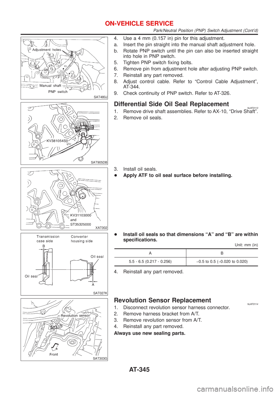
SAT480J
4. Usea4mm(0.157 in) pin for this adjustment.
a. Insert the pin straight into the manual shaft adjustment hole.
b. Rotate PNP switch until the pin can also be inserted straight
into hole in PNP switch.
5. Tighten PNP switch fixing bolts.
6. Remove pin from adjustment hole after adjusting PNP switch.
7. Reinstall any part removed.
8. Adjust control cable. Refer to ªControl Cable Adjustmentº,
AT-344.
9. Check continuity of PNP switch. Refer to AT-326.
SAT905DB
Differential Side Oil Seal ReplacementNJAT01131. Remove drive shaft assemblies. Refer to AX-10, ªDrive Shaftº.
2. Remove oil seals.
XAT002
3. Install oil seals.
+Apply ATF to oil seal surface before installing.
SAT027K
+Install oil seals so that dimensions ªAº and ªBº are within
specifications.
Unit: mm (in)
AB
5.5 - 6.5 (0.217 - 0.256) þ0.5 to 0.5 (þ0.020 to 0.020)
4. Reinstall any part removed.
SAT303G
Revolution Sensor ReplacementNJAT01141. Disconnect revolution sensor harness connector.
2. Remove harness bracket from A/T.
3. Remove revolution sensor from A/T.
4. Reinstall any part removed.
Always use new sealing parts.
ON-VEHICLE SERVICE
Park/Neutral Position (PNP) Switch Adjustment (Cont'd)
AT-345
Page 1543 of 2493
SAT023DA
16. Check accumulator pistons and contact surface of transmis-
sion case for damage.
17. Check accumulator return springs for damage and free length.
Return springs:
Refer to SDS, AT-457.
SAT129E
18. Remove lip seals from band servo oil port.
SAT027D
19. Remove converter housing according to the following proce-
dures.
a. Remove converter housing mounting bolts A and B.
SAT028D
b. Remove converter housing.
SAT131E
c. Remove O-ring from differential oil port.
DISASSEMBLY
AT-357
Page 1544 of 2493
SAT030D
20. Remove final drive assembly from transmission case.
NAT033
21. Remove differential side bearing outer race from transmission
case.
SAT132E
22. Remove differential side bearing adjusting shim from transmis-
sion case.
SAT840DB
23. Remove differential side bearing outer race from converter
housing.
SAT133E
24. Remove oil seal from converter housing using a screwdriver.
+Be careful not to damage case.
DISASSEMBLY
AT-358
Page 1610 of 2493
Final Drive
COMPONENTSNJAT0169
SAT040K
SAT311D
DISASSEMBLYNJAT01701. Remove final gear.
SAT099K
2. Press out differential side bearings.
SAT313D
3. Remove speedometer drive gear.
REPAIR FOR COMPONENT PARTS
Final Drive
AT-424
Page 1611 of 2493
SAT970H
4. Drive out pinion mate shaft lock pin.
SAT316D
5. Draw out pinion mate shaft from differential case.
6. Remove pinion mate gears and side gears.
SAT041K
INSPECTIONNJAT0171Gear, Washer, Shaft and CaseNJAT0171S01+Check mating surfaces of differential case, side gears, pinion
and mate gears.
+Check washers for wear.
SPD715
BearingsNJAT0171S03+Make sure bearings roll freely and are free from noise, cracks,
pitting or wear.
+When replacing taper roller bearing, replace outer and
inner race as a set.
SAT318D
ASSEMBLYNJAT01721. Install side gear and thrust washers in differential case.
2. Install pinion mate gears and thrust washers in differential case
while rotating them.
+When inserting, be careful not to damage pinion mate gear
washers.
+Apply ATF to any parts.
REPAIR FOR COMPONENT PARTS
Final Drive (Cont'd)
AT-425
Page 1612 of 2493
NAT056
3. Measure clearance between side gear and differential case
with washers using the following procedure.
a. Set Tool and dial indicator on side gear.
b. Move side gear up and down to measure dial indicator deflec-
tion. Always measure indicator deflection on both side gears.
Clearance between side gear and differential case with
washers:
0.1 - 0.2 mm (0.004 - 0.008 in)
SMT616
c. If not within specification adjust clearance by changing thick-
ness of side gear thrust washers.
Side gear thrust washer:
Refer to SDS, AT-453.
SAT970H
4. Install lock pin.
+Make sure that lock pin is flush with case.
SAT313D
5. Install speedometer drive gear on differential case.
+Align the projection of speedometer drive gear with the
groove of differential case.
SAT326D
6. Install final gear and tighten fixing bolts in numerical order.
REPAIR FOR COMPONENT PARTS
Final Drive (Cont'd)
AT-426