Page 631 of 2493

ECM Terminals and Reference Value=NJEC0487Specification data are reference values and are measured between each terminal and ground.
CAUTION:
Do not use ECM ground terminals when measuring input/output voltage. Doing so may result in dam-
age to the ECM's transistor. Use a ground other than ECM terminals, such as the ground.
TERMI-
NAL
NO.WIRE
COLORITEM CONDITION DATA (DC Voltage)
13 LG/R Cooling fan relay[Engine is running]
+Cooling fan is not operatingBATTERY VOLTAGE
(11 - 14V)
[Engine is running]
+Cooling fan is operating0 - 0.6V
23 L/W Air conditioner switch[Engine is running]
+Both air conditioner switch and blower switch are
ªONº (Compressor operates)Approximately 0V
[Engine is running]
+Air conditioner switch is ªOFFºBATTERY VOLTAGE
(11 - 14V)
On Board Diagnosis LogicNJEC0572If the cooling fan or another component in the cooling system malfunctions, engine coolant temperature will
rise.
When the engine coolant temperature reaches an abnormally high temperature condition, a malfunction is
indicated.
DTC No. Malfunction is detected when ... Check Items (Possible Cause)
P1217
1217+The engine coolant temperature is extraordinary high,
even when the load is not heavy.+Harness or connectors
(The cooling fan circuit is open or shorted)
+Cooling fan
+Thermostat
+Improper ignition timing
+Engine coolant temperature sensor
+Blocked radiator
+Blocked front end (Improper fitting of nose mask)
+Crushed vehicle frontal area (Vehicle frontal is
collided but not repaired)
+Blocked air passage by improper installation of
front fog lamp or fog lamps.
+Improper mixture ratio of coolant
+Damaged bumper
For more information, refer to ªMAIN 12 CAUSES
OF OVERHEATINGº, EC-345.
CAUTION:
When a malfunction is indicated, be sure to replace the coolant following the procedure in the LC-17,
ªChanging Engine Coolantº. Also, replace the engine oil.
1) Fill radiator with coolant up to specified level with a filling speed of 2 liters per minute. Be sure to use
coolant with the proper mixture ratio. Refer to MA-22, ªAnti-freeze Coolant Mixture Ratioº, ªRECOM-
MENDED FLUIDS AND LUBRICANTSº.
2) After refilling coolant, run engine to ensure that no water-flow noise is emitted.
DTC P1217 OVERHEAT (COOLING SYSTEM)QG
ECM Terminals and Reference Value
EC-335
Page 636 of 2493
3 CHECK POWER SUPPLY
1. Turn ignition switch ªOFFº.
2. Disconnect cooling fan relay (For Europe) or cooling fan relay-land-2 (For Australia).
SEF628Y
3. Turn ignition switch ªONº.
4. Check voltage between terminals 1, 3, 6 (For Europe) or 2, 3 (For Australia) and ground with CONSULT-II or tester.
YEC055A
OK or NG
OK©GO TO 5.
NG©GO TO 4.
4 DETECT MALFUNCTIONING PART
Check the following.
+10A fuse
+30A fusible link (For Europe)
+40A fusible link (For Australia)
+Harness for open or short between cooling fan relay and fuse
©Repair open circuit or short to ground or short to power in harness or connectors.
DTC P1217 OVERHEAT (COOLING SYSTEM)QG
Diagnostic Procedure (Cont'd)
EC-340
Page 637 of 2493
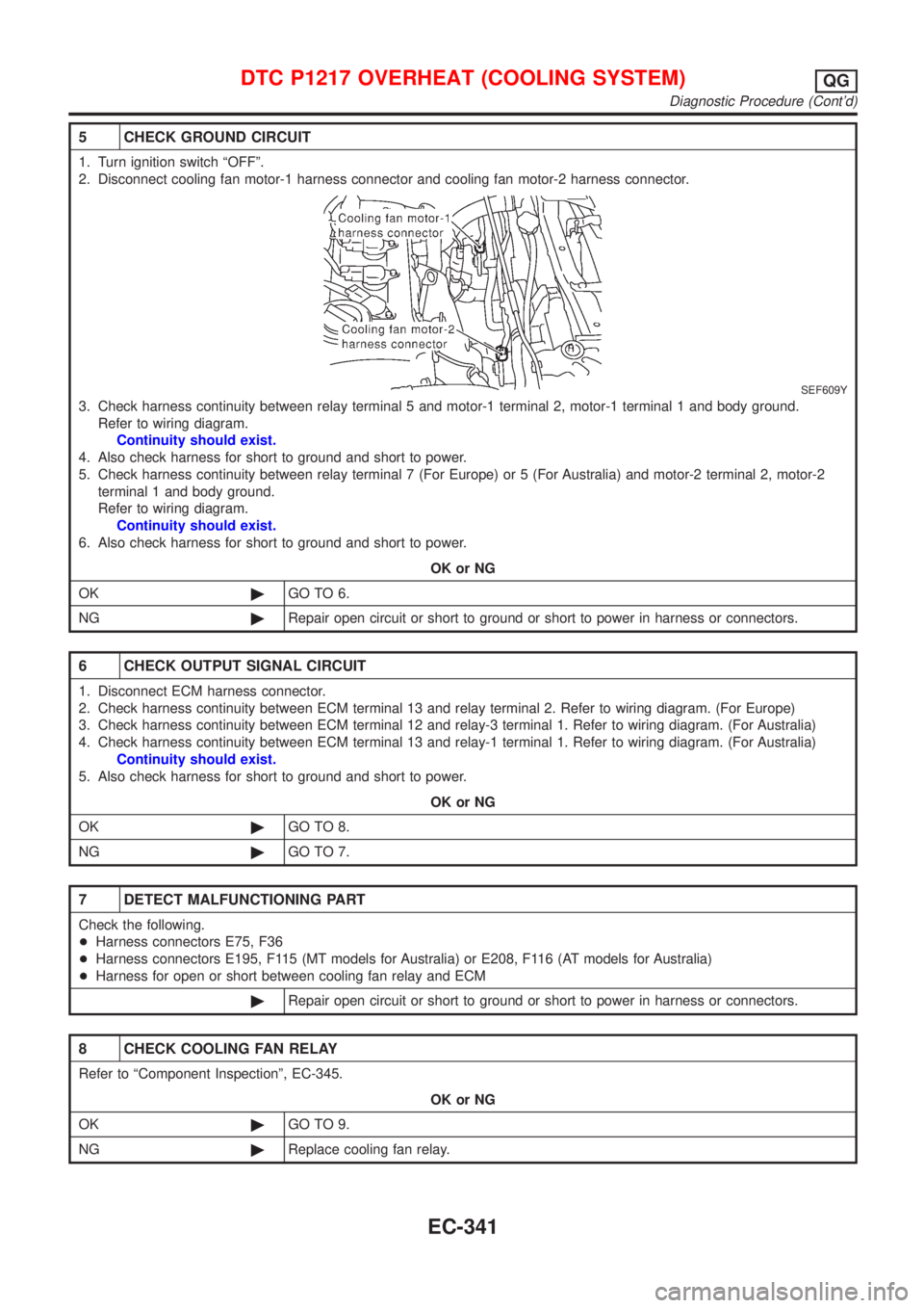
5 CHECK GROUND CIRCUIT
1. Turn ignition switch ªOFFº.
2. Disconnect cooling fan motor-1 harness connector and cooling fan motor-2 harness connector.
SEF609Y
3. Check harness continuity between relay terminal 5 and motor-1 terminal 2, motor-1 terminal 1 and body ground.
Refer to wiring diagram.
Continuity should exist.
4. Also check harness for short to ground and short to power.
5. Check harness continuity between relay terminal 7 (For Europe) or 5 (For Australia) and motor-2 terminal 2, motor-2
terminal 1 and body ground.
Refer to wiring diagram.
Continuity should exist.
6. Also check harness for short to ground and short to power.
OK or NG
OK©GO TO 6.
NG©Repair open circuit or short to ground or short to power in harness or connectors.
6 CHECK OUTPUT SIGNAL CIRCUIT
1. Disconnect ECM harness connector.
2. Check harness continuity between ECM terminal 13 and relay terminal 2. Refer to wiring diagram. (For Europe)
3. Check harness continuity between ECM terminal 12 and relay-3 terminal 1. Refer to wiring diagram. (For Australia)
4. Check harness continuity between ECM terminal 13 and relay-1 terminal 1. Refer to wiring diagram. (For Australia)
Continuity should exist.
5. Also check harness for short to ground and short to power.
OK or NG
OK©GO TO 8.
NG©GO TO 7.
7 DETECT MALFUNCTIONING PART
Check the following.
+Harness connectors E75, F36
+Harness connectors E195, F115 (MT models for Australia) or E208, F116 (AT models for Australia)
+Harness for open or short between cooling fan relay and ECM
©Repair open circuit or short to ground or short to power in harness or connectors.
8 CHECK COOLING FAN RELAY
Refer to ªComponent Inspectionº, EC-345.
OK or NG
OK©GO TO 9.
NG©Replace cooling fan relay.
DTC P1217 OVERHEAT (COOLING SYSTEM)QG
Diagnostic Procedure (Cont'd)
EC-341
Page 641 of 2493
Main 12 Causes of Overheating=NJEC0492
Engine Step Inspection item Equipment Standard Reference page
OFF 1+Blocked radiator
+Blocked condenser
+Blocked radiator grille
+Blocked bumper+Visual No blocking Ð
2+Coolant mixture+Coolant tester 50 - 50% coolant mixture See MA-20, ªRECOM-
MENDED FLUIDS AND
LUBRICANTSº.
3+Coolant level+Visual Coolant up to MAX level
in reservoir tank and
radiator filler neckSee LC-17, ªChanging
Engine Coolantº.
4+Radiator cap+Pressure tester 59 - 98 kPa
(0.59 - 0.98 bar, 0.6 - 1.0
kg/cm
2,9-14psi) (Limit)See LC-10, ªSystem
Checkº.
ON*
25+Coolant leaks+Visual No leaks See LC-10, ªSystem
Checkº.
ON*
26+Thermostat+Touch the upper and
lower radiator hosesBoth hoses should be
hotSee LC-15, ªThermostatº
and LC-16, ªRadiatorº.
ON*
17+Cooling fan+CONSULT-II Operating See ªTROUBLE DIAG-
NOSIS FOR OVER-
HEATº (EC-334).
OFF 8+Combustion gas leak+Color checker chemi-
cal tester 4 Gas ana-
lyzerNegative Ð
ON*
39+Coolant temperature
gauge+Visual Gauge less than 3/4
when drivingÐ
+Coolant overflow to
reservoir tank+Visual No overflow during driv-
ing and idlingSee LC-17, ªChanging
Engine Coolantº.
OFF*
410+Coolant return from
reservoir tank to radia-
tor+Visual Should be initial level in
reservoir tankSee LC-18, ªRefilling
Engine Coolantº.
OFF 11+Cylinder head+Straight gauge feeler
gauge0.1 mm (0.004 in) Maxi-
mum distortion (warping)See EM-36, ªInspectionº,
ªCYLINDER HEADº.
12+Cylinder block and
pistons+Visual No scuffing on cylinder
walls or pistonSee EM-54, ªInspectionº,
ªCYLINDER BLOCKº.
*1: Turn the ignition switch ON.
*2: Engine running at 3,000 rpm for 10 minutes.
*3: Drive at 90 km/h (55 MPH) for 30 minutes and then let idle for 10 minutes.
*4: After 60 minutes of cool down time.
For more information, refer to LC-23, ª OVERHEATING CAUSE ANALYSISº.
SEF745U
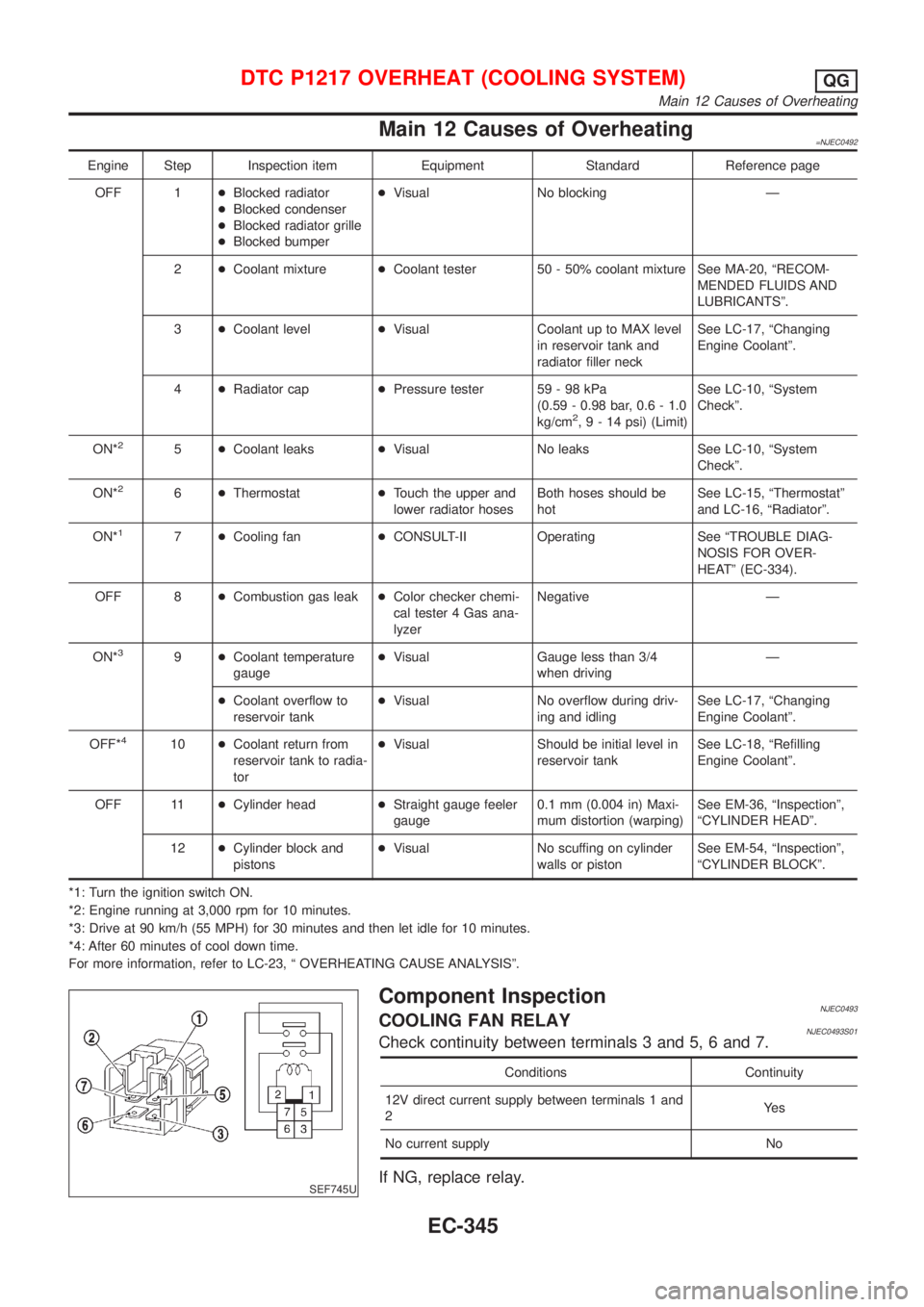
Component InspectionNJEC0493COOLING FAN RELAYNJEC0493S01Check continuity between terminals 3 and 5, 6 and 7.
Conditions Continuity
12V direct current supply between terminals 1 and
2Ye s
No current supply No
If NG, replace relay.
DTC P1217 OVERHEAT (COOLING SYSTEM)QG
Main 12 Causes of Overheating
EC-345
Page 654 of 2493
Diagnostic ProcedureNJEC0353
1 CHECK POWER SUPPLY
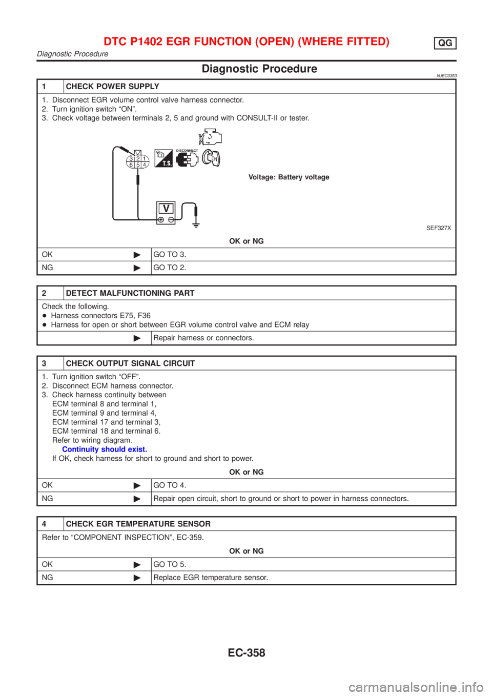
1. Disconnect EGR volume control valve harness connector.
2. Turn ignition switch ªONº.
3. Check voltage between terminals 2, 5 and ground with CONSULT-II or tester.
SEF327X
OK or NG
OK©GO TO 3.
NG©GO TO 2.
2 DETECT MALFUNCTIONING PART
Check the following.
+Harness connectors E75, F36
+Harness for open or short between EGR volume control valve and ECM relay
©Repair harness or connectors.
3 CHECK OUTPUT SIGNAL CIRCUIT
1. Turn ignition switch ªOFFº.
2. Disconnect ECM harness connector.
3. Check harness continuity between
ECM terminal 8 and terminal 1,
ECM terminal 9 and terminal 4,
ECM terminal 17 and terminal 3,
ECM terminal 18 and terminal 6.
Refer to wiring diagram.
Continuity should exist.
If OK, check harness for short to ground and short to power.
OK or NG
OK©GO TO 4.
NG©Repair open circuit, short to ground or short to power in harness connectors.
4 CHECK EGR TEMPERATURE SENSOR
Refer to ªCOMPONENT INSPECTIONº, EC-359.
OK or NG
OK©GO TO 5.
NG©Replace EGR temperature sensor.
DTC P1402 EGR FUNCTION (OPEN) (WHERE FITTED)QG
Diagnostic Procedure
EC-358
Page 693 of 2493
3 CHECK POWER SUPPLY
1. Disconnect crankshaft position sensor harness connector.
JEF835Z
2. Turn ignition switch ªONº.
3. Check voltage between terminal 3 and ground with CONSULT-II or tester.
SEF113Y
OK or NG
OK©GO TO 5.
NG©GO TO 4.
4 DETECT MALFUNCTIONING PART
Check the following.
+Joint connector-6
+Harness for open or short between joint connector and ECM relay
+Harness for open or short between crankshaft position sensor and joint connector
+Harness for open or short between joint connector and ECM
+ECM relay
©Repair open circuit or short to ground or short to power in harness or connectors.
CRANKSHAFT POSITION SENSOR (POS)QG
Diagnostic Procedure (Cont'd)
EC-397
Page 703 of 2493
7 CHECK EGR TEMPERATURE SENSOR GROUND CIRCUIT
1. Turn ignition switch ªOFFº.
2. Check harness continuity between EGR temperature sensor harness terminal 2 and engine ground.
Refer to wiring diagram.
Continuity should exist.
3. Also check harness for short to ground and short to power.
OK or NG
OK©GO TO 9.
NG©GO TO 8.
8 DETECT MALFUNCTIONING PART
Check the following.
+Harness for open or short between EGR temperature sensor and ECM
+Harness for open or short between TCM (Transmission Control Module) and ECM
+Joint connector-6
©Repair open circuit or short to ground or short to power in harness or connector.
9 CHECK EGR TEMPERATURE SENSOR
Refer to ªComponent Inspectionº, EC-410.
OK or NG
OK©GO TO 10.
NG©Replace EGR temperature sensor.
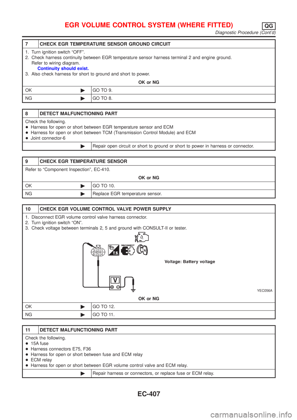
10 CHECK EGR VOLUME CONTROL VALVE POWER SUPPLY
1. Disconnect EGR volume control valve harness connector.
2. Turn ignition switch ªONº.
3. Check voltage between terminals 2, 5 and ground with CONSULT-II or tester.
YEC056A
OK or NG
OK©GO TO 12.
NG©GO TO 11.
11 DETECT MALFUNCTIONING PART
Check the following.
+15A fuse
+Harness connectors E75, F36
+Harness for open or short between fuse and ECM relay
+ECM relay
+Harness for open or short between EGR volume control valve and ECM relay.
©Repair harness or connectors, or replace fuse or ECM relay.
EGR VOLUME CONTROL SYSTEM (WHERE FITTED)QG
Diagnostic Procedure (Cont'd)
EC-407
Page 718 of 2493
3 DETECT MALFUNCTIONING PART
Check the following.
+15A fuse
+Harness connectors E75, F36 (If so equipped)
+Harness for open or short between fuse and ECM relay
+ECM relay
+Harness for open or short between IACV-AAC and ECM relay.
©Repair harness or connectors, or replace fuse or ECM relay.
4 CHECK OUTPUT SIGNAL CIRCUIT
1. Turn ignition switch ªOFFº.
2. Disconnect ECM harness connector.
3. Check harness continuity between
ECM terminal 6 and IACV-AAC valve terminal 1,
ECM terminal 7 and IACV-AAC valve terminal 4,
ECM terminal 15 and IACV-AAC valve terminal 3,
ECM terminal 16 and IACV-AAC valve terminal 6.
Refer to wiring diagram.
Continuity should exist.
4. Also check harness for short to ground and short to power.
OK or NG
OK©GO TO 5.
NG©Repair open circuit or short to ground or short to power in harness or connectors.
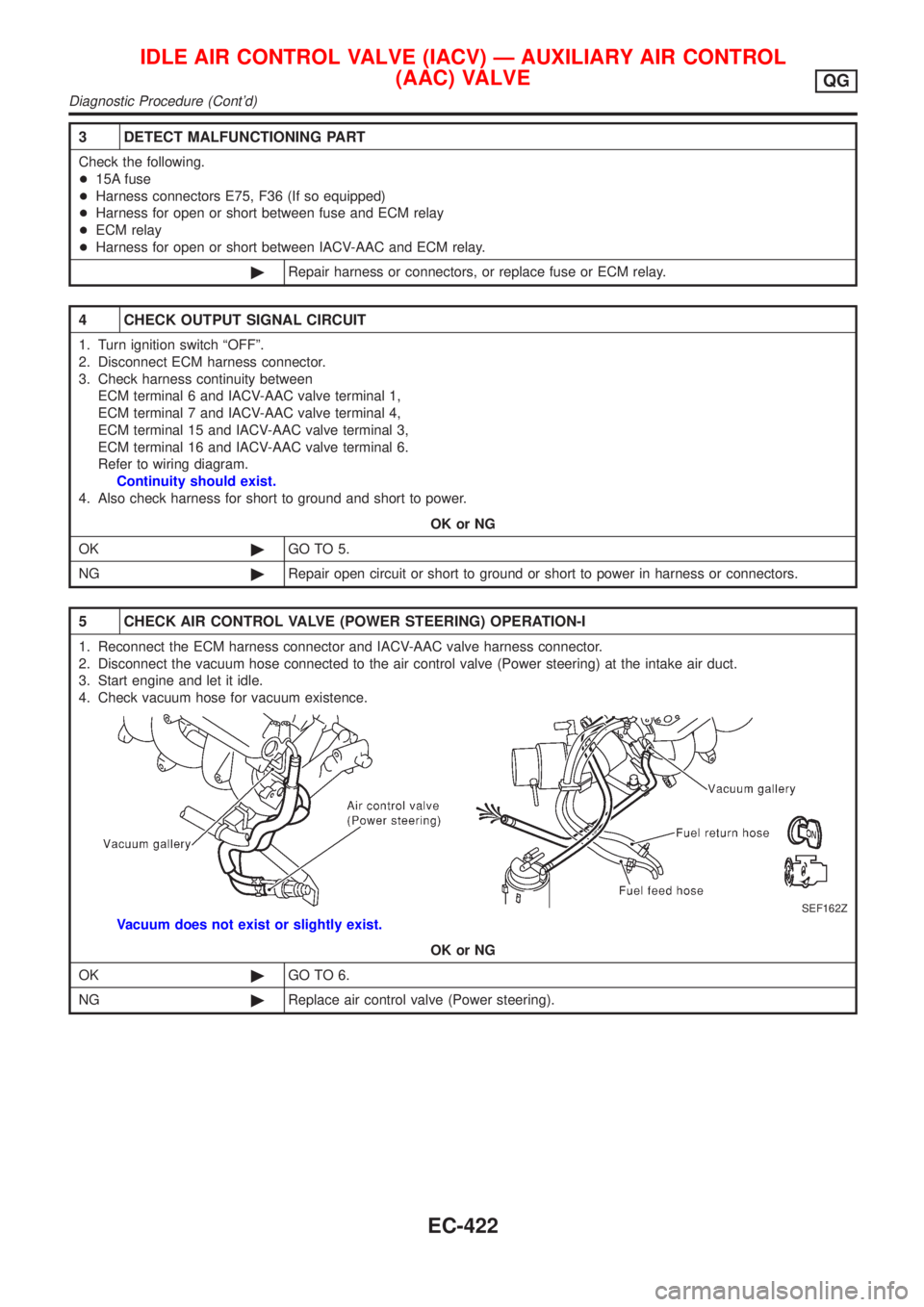
5 CHECK AIR CONTROL VALVE (POWER STEERING) OPERATION-I
1. Reconnect the ECM harness connector and IACV-AAC valve harness connector.
2. Disconnect the vacuum hose connected to the air control valve (Power steering) at the intake air duct.
3. Start engine and let it idle.
4. Check vacuum hose for vacuum existence.
SEF162Z
Vacuum does not exist or slightly exist.
OK or NG
OK©GO TO 6.
NG©Replace air control valve (Power steering).
IDLE AIR CONTROL VALVE (IACV) Ð AUXILIARY AIR CONTROL
(AAC) VALVE
QG
Diagnostic Procedure (Cont'd)
EC-422