Page 447 of 2493
16 CHECK ECM RELAY
1. Apply 12V direct current between ECM relay terminals 1 and 2.
2. Check continuity between relay terminals 3 and 5, 6 and 7.
SEF296X
OK or NG
OK©GO TO 17.
NG©Replace ECM relay.
17 CHECK ECM GROUND CIRCUIT FOR OPEN AND SHORT-II
1. Turn ignition switch ªOFFº.
2. Disconnect ECM harness connector.
3. Check harness continuity between ECM terminals 48, 57, 106, 108 and engine ground.
Refer to WIRING DIAGRAM.
Continuity should exist.
4. Also check harness for short to ground and short to power.
OK or NG
OK©GO TO 18.
NG©Repair open circuit or short to ground or short to power in harness or connectors.
18 CHECK INTERMITTENT INCIDENT
Refer to ªTROUBLE DIAGNOSIS FOR INTERMITTENT INCIDENTº, EC-144.
©INSPECTION END
TROUBLE DIAGNOSIS FOR POWER SUPPLYQG
Main Power Supply and Ground Circuit (Cont'd)
EC-151
Page 452 of 2493
4 CHECK POWER SUPPLY
1. Disconnect mass air flow sensor harness connector.
JEF105Y
2. Turn ignition switch ªONº.
3. Check voltage between terminal 2, 4 and ground with CONSULT-II or tester.
SEF297X
OK or NG
OK©GO TO 6.
NG©GO TO 5.
5 DETECT MALFUNCTIONING PART
Check the following.
+Joint connector-6
+Harness for open or short between ECM relay and mass air flow sensor
+Harness for open or short between mass air flow sensor and ECM
©Repair harness or connectors.
6 CHECK GROUND CIRCUIT
1. Turn ignition switch ªOFFº.
2. Disconnect ECM harness connector.
3. Check harness continuity between mass air flow sensor harness connector terminal 3 and ECM terminal 73.
Refer to wiring diagram.
Continuity should exist.
4. Also check harness for short to ground and short to power.
OK or NG
OK©GO TO 7.
NG©Repair open circuit or short to ground or short to power in harness or connectors.
DTC P0100 MASS AIR FLOW SENSOR (MAFS)QG
Diagnostic Procedure (Cont'd)
EC-156
Page 572 of 2493
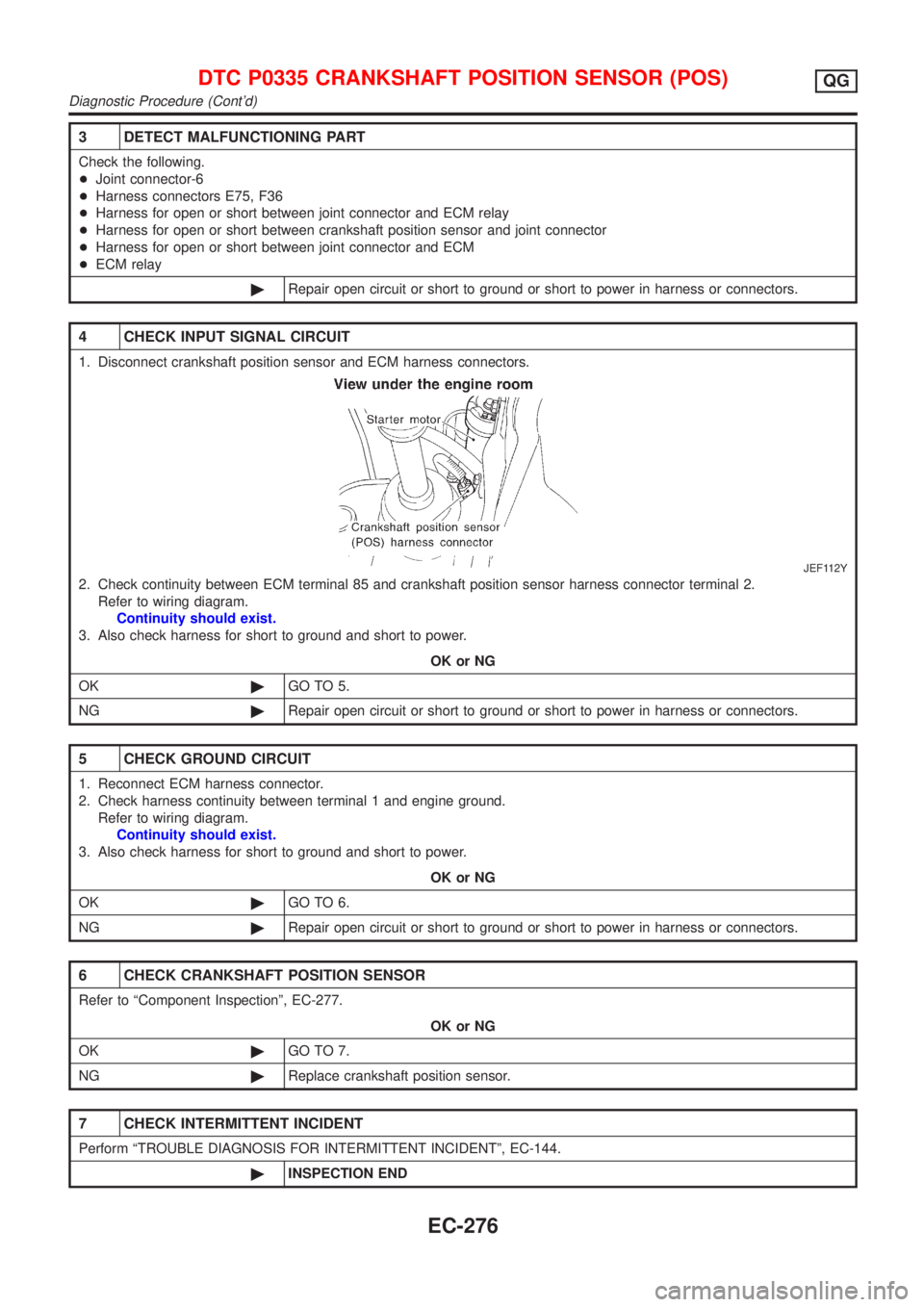
3 DETECT MALFUNCTIONING PART
Check the following.
+Joint connector-6
+Harness connectors E75, F36
+Harness for open or short between joint connector and ECM relay
+Harness for open or short between crankshaft position sensor and joint connector
+Harness for open or short between joint connector and ECM
+ECM relay
©Repair open circuit or short to ground or short to power in harness or connectors.
4 CHECK INPUT SIGNAL CIRCUIT
1. Disconnect crankshaft position sensor and ECM harness connectors.
JEF112Y
2. Check continuity between ECM terminal 85 and crankshaft position sensor harness connector terminal 2.
Refer to wiring diagram.
Continuity should exist.
3. Also check harness for short to ground and short to power.
OK or NG
OK©GO TO 5.
NG©Repair open circuit or short to ground or short to power in harness or connectors.
5 CHECK GROUND CIRCUIT
1. Reconnect ECM harness connector.
2. Check harness continuity between terminal 1 and engine ground.
Refer to wiring diagram.
Continuity should exist.
3. Also check harness for short to ground and short to power.
OK or NG
OK©GO TO 6.
NG©Repair open circuit or short to ground or short to power in harness or connectors.
6 CHECK CRANKSHAFT POSITION SENSOR
Refer to ªComponent Inspectionº, EC-277.
OK or NG
OK©GO TO 7.
NG©Replace crankshaft position sensor.
7 CHECK INTERMITTENT INCIDENT
Perform ªTROUBLE DIAGNOSIS FOR INTERMITTENT INCIDENTº, EC-144.
©INSPECTION END
DTC P0335 CRANKSHAFT POSITION SENSOR (POS)QG
Diagnostic Procedure (Cont'd)
EC-276
Page 578 of 2493
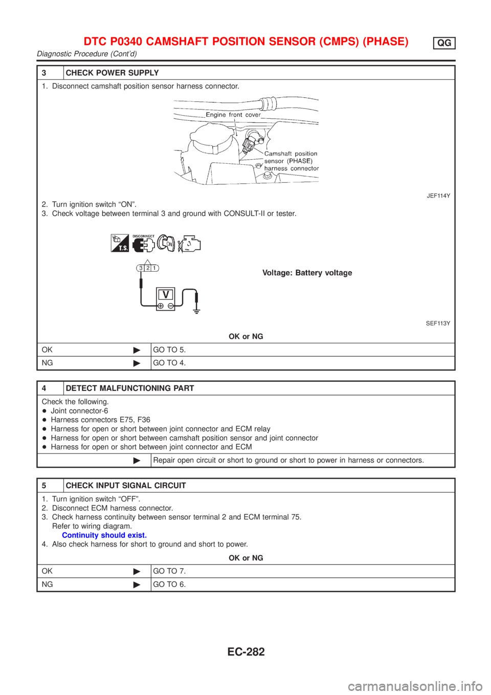
3 CHECK POWER SUPPLY
1. Disconnect camshaft position sensor harness connector.
JEF114Y
2. Turn ignition switch ªONº.
3. Check voltage between terminal 3 and ground with CONSULT-II or tester.
SEF113Y
OK or NG
OK©GO TO 5.
NG©GO TO 4.
4 DETECT MALFUNCTIONING PART
Check the following.
+Joint connector-6
+Harness connectors E75, F36
+Harness for open or short between joint connector and ECM relay
+Harness for open or short between camshaft position sensor and joint connector
+Harness for open or short between joint connector and ECM
©Repair open circuit or short to ground or short to power in harness or connectors.
5 CHECK INPUT SIGNAL CIRCUIT
1. Turn ignition switch ªOFFº.
2. Disconnect ECM harness connector.
3. Check harness continuity between sensor terminal 2 and ECM terminal 75.
Refer to wiring diagram.
Continuity should exist.
4. Also check harness for short to ground and short to power.
OK or NG
OK©GO TO 7.
NG©GO TO 6.
DTC P0340 CAMSHAFT POSITION SENSOR (CMPS) (PHASE)QG
Diagnostic Procedure (Cont'd)
EC-282
Page 586 of 2493
Diagnostic ProcedureNJEC0232
1 CHECK EXHAUST SYSTEM
1. Start engine.
2. Check exhaust pipes and muffler for leaks.
SEF099P
OK or NG
OK (With CONSULT-II)©GO TO 2.
OK (Without CONSULT-
II)©GO TO 4.
NG©Repair or replace exhaust system.
2 CHECK POWER SUPPLY
1. Disconnect EGR volume control valve harness connector.
2. Turn ignition switch ªONº.
3. Check voltage between terminals 2, 5 and ground with CONSULT-II or tester.
SEF327X
OK or NG
OK©GO TO 4.
NG©GO TO 3.
3 DETECT MALFUNCTIONING PART
Check the following.
+Harness connectors E75, F36
+Harness for open or short between EGR volume control valve and ECM relay
©Repair harness or connectors.
DTC P0400 EGR FUNCTION (CLOSED) (WHERE FITTED)QG
Diagnostic Procedure
EC-290
Page 593 of 2493
Diagnostic ProcedureNJEC0511
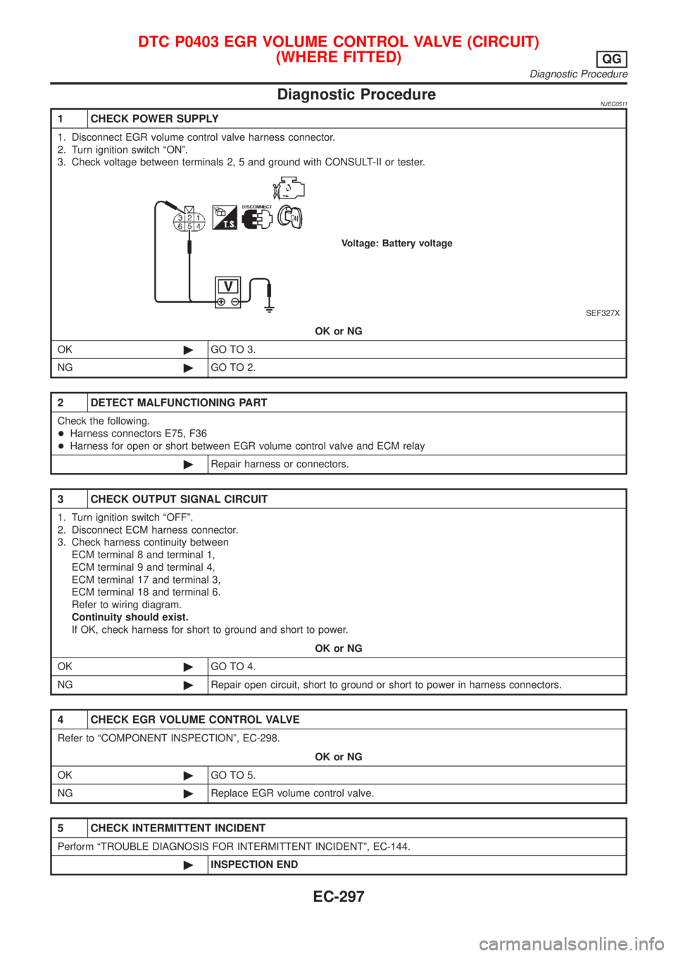
1 CHECK POWER SUPPLY
1. Disconnect EGR volume control valve harness connector.
2. Turn ignition switch ªONº.
3. Check voltage between terminals 2, 5 and ground with CONSULT-II or tester.
SEF327X
OK or NG
OK©GO TO 3.
NG©GO TO 2.
2 DETECT MALFUNCTIONING PART
Check the following.
+Harness connectors E75, F36
+Harness for open or short between EGR volume control valve and ECM relay
©Repair harness or connectors.
3 CHECK OUTPUT SIGNAL CIRCUIT
1. Turn ignition switch ªOFFº.
2. Disconnect ECM harness connector.
3. Check harness continuity between
ECM terminal 8 and terminal 1,
ECM terminal 9 and terminal 4,
ECM terminal 17 and terminal 3,
ECM terminal 18 and terminal 6.
Refer to wiring diagram.
Continuity should exist.
If OK, check harness for short to ground and short to power.
OK or NG
OK©GO TO 4.
NG©Repair open circuit, short to ground or short to power in harness connectors.
4 CHECK EGR VOLUME CONTROL VALVE
Refer to ªCOMPONENT INSPECTIONº, EC-298.
OK or NG
OK©GO TO 5.
NG©Replace EGR volume control valve.
5 CHECK INTERMITTENT INCIDENT
Perform ªTROUBLE DIAGNOSIS FOR INTERMITTENT INCIDENTº, EC-144.
©INSPECTION END
DTC P0403 EGR VOLUME CONTROL VALVE (CIRCUIT)
(WHERE FITTED)
QG
Diagnostic Procedure
EC-297
Page 612 of 2493
Diagnostic ProcedureNJEC0285
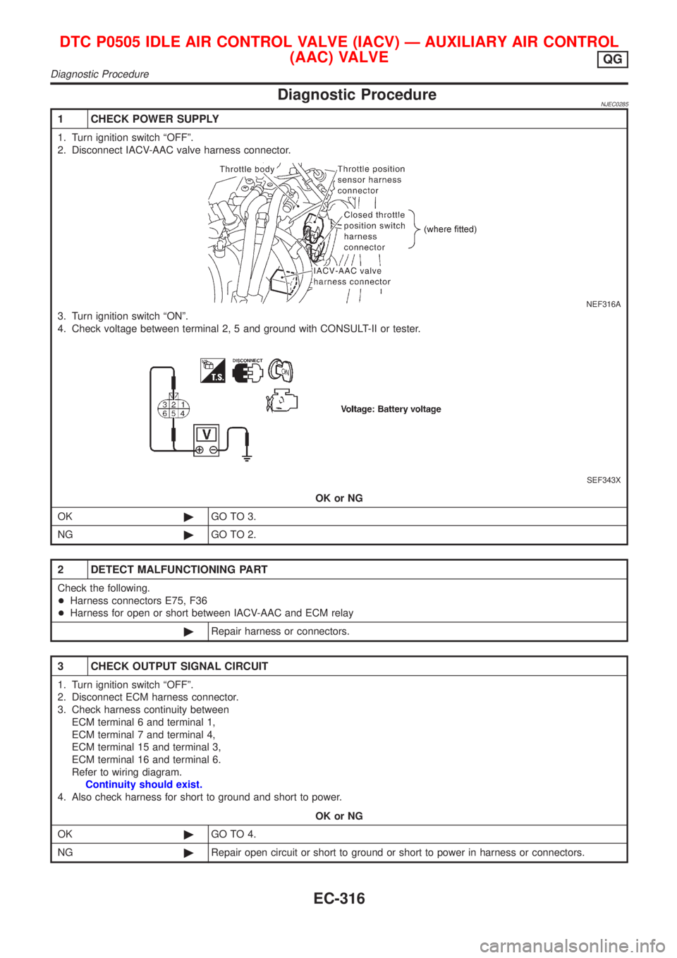
1 CHECK POWER SUPPLY
1. Turn ignition switch ªOFFº.
2. Disconnect IACV-AAC valve harness connector.
NEF316A
3. Turn ignition switch ªONº.
4. Check voltage between terminal 2, 5 and ground with CONSULT-II or tester.
SEF343X
OK or NG
OK©GO TO 3.
NG©GO TO 2.
2 DETECT MALFUNCTIONING PART
Check the following.
+Harness connectors E75, F36
+Harness for open or short between IACV-AAC and ECM relay
©Repair harness or connectors.
3 CHECK OUTPUT SIGNAL CIRCUIT
1. Turn ignition switch ªOFFº.
2. Disconnect ECM harness connector.
3. Check harness continuity between
ECM terminal 6 and terminal 1,
ECM terminal 7 and terminal 4,
ECM terminal 15 and terminal 3,
ECM terminal 16 and terminal 6.
Refer to wiring diagram.
Continuity should exist.
4. Also check harness for short to ground and short to power.
OK or NG
OK©GO TO 4.
NG©Repair open circuit or short to ground or short to power in harness or connectors.
DTC P0505 IDLE AIR CONTROL VALVE (IACV) Ð AUXILIARY AIR CONTROL
(AAC) VALVE
QG
Diagnostic Procedure
EC-316
Page 630 of 2493
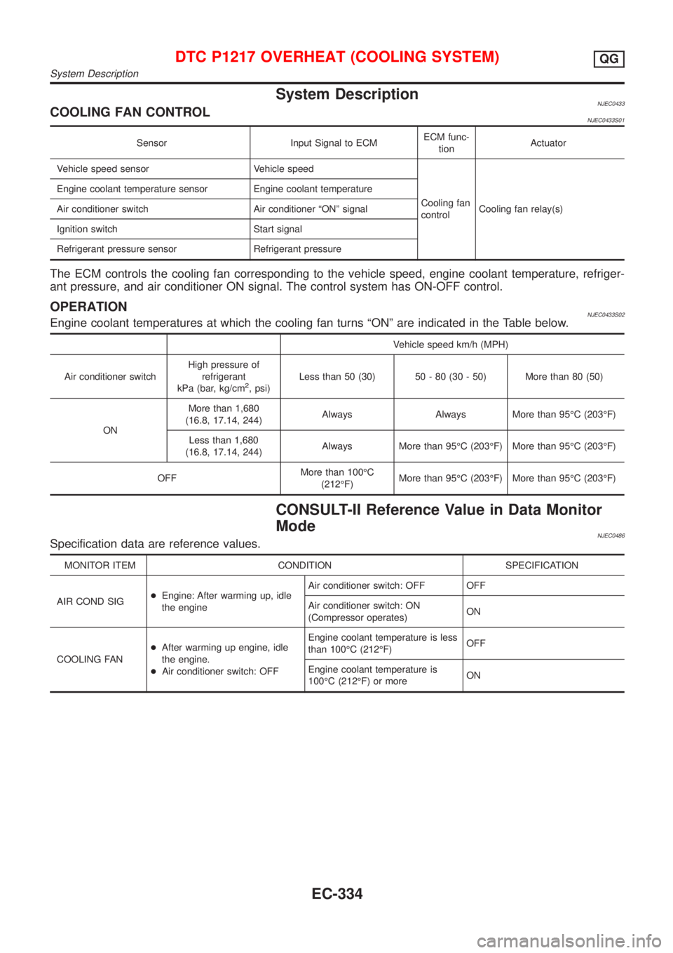
System DescriptionNJEC0433COOLING FAN CONTROLNJEC0433S01
Sensor Input Signal to ECMECM func-
tionActuator
Vehicle speed sensor Vehicle speed
Cooling fan
controlCooling fan relay(s) Engine coolant temperature sensor Engine coolant temperature
Air conditioner switch Air conditioner ªONº signal
Ignition switch Start signal
Refrigerant pressure sensor Refrigerant pressure
The ECM controls the cooling fan corresponding to the vehicle speed, engine coolant temperature, refriger-
ant pressure, and air conditioner ON signal. The control system has ON-OFF control.
OPERATIONNJEC0433S02Engine coolant temperatures at which the cooling fan turns ªONº are indicated in the Table below.
Vehicle speed km/h (MPH)
Air conditioner switchHigh pressure of
refrigerant
kPa (bar, kg/cm
2, psi)Less than 50 (30) 50 - 80 (30 - 50) More than 80 (50)
ONMore than 1,680
(16.8, 17.14, 244)Always Always More than 95ÉC (203ÉF)
Less than 1,680
(16.8, 17.14, 244)Always More than 95ÉC (203ÉF) More than 95ÉC (203ÉF)
OFFMore than 100ÉC
(212ÉF)More than 95ÉC (203ÉF) More than 95ÉC (203ÉF)
CONSULT-II Reference Value in Data Monitor
Mode
NJEC0486Specification data are reference values.
MONITOR ITEM CONDITION SPECIFICATION
AIR COND SIG+Engine: After warming up, idle
the engineAir conditioner switch: OFF OFF
Air conditioner switch: ON
(Compressor operates)ON
COOLING FAN+After warming up engine, idle
the engine.
+Air conditioner switch: OFFEngine coolant temperature is less
than 100ÉC (212ÉF)OFF
Engine coolant temperature is
100ÉC (212ÉF) or moreON
DTC P1217 OVERHEAT (COOLING SYSTEM)QG
System Description
EC-334