2001 NISSAN ALMERA N16 check engine light
[x] Cancel search: check engine lightPage 551 of 2493
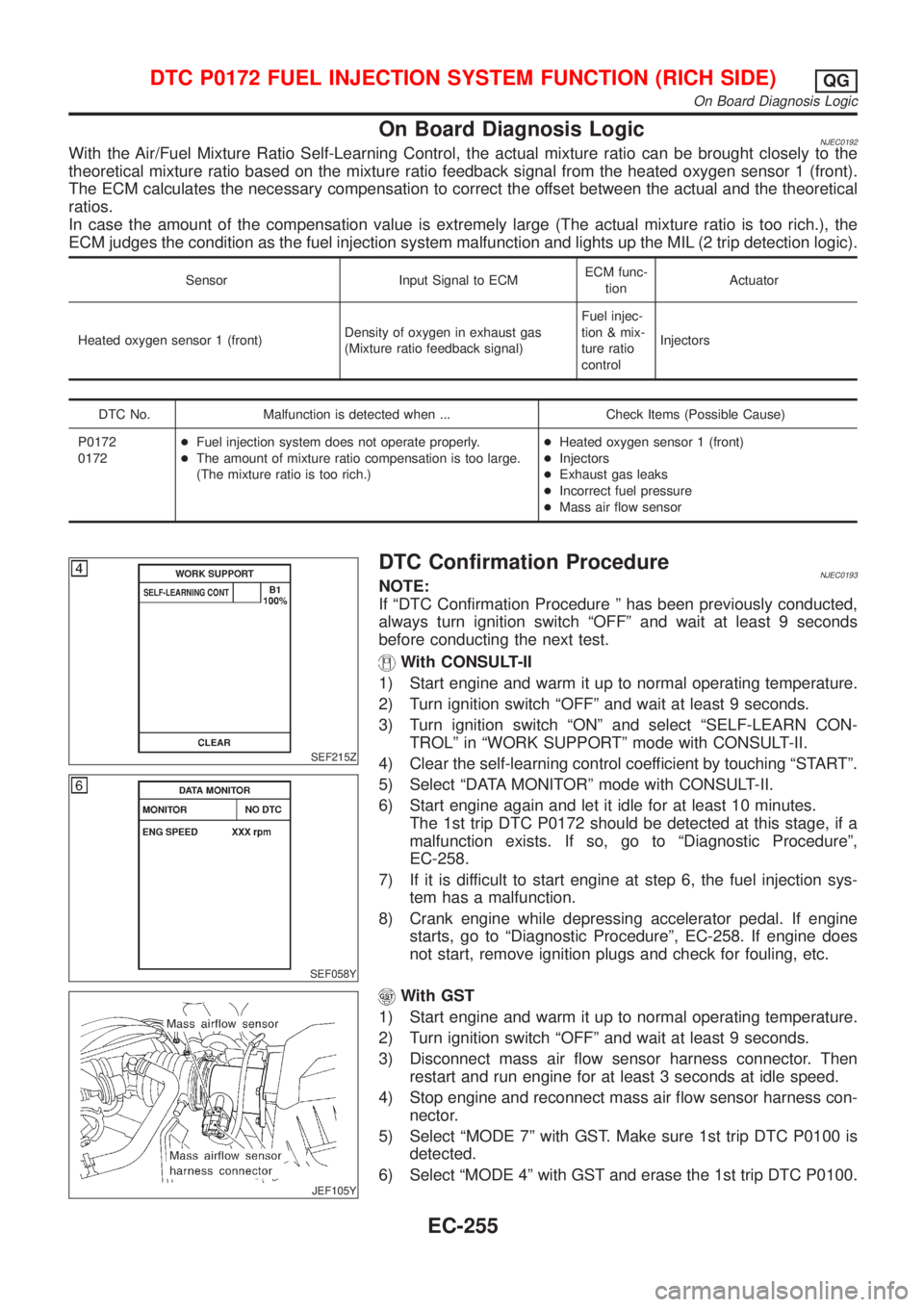
On Board Diagnosis LogicNJEC0192With the Air/Fuel Mixture Ratio Self-Learning Control, the actual mixture ratio can be brought closely to the
theoretical mixture ratio based on the mixture ratio feedback signal from the heated oxygen sensor 1 (front).
The ECM calculates the necessary compensation to correct the offset between the actual and the theoretical
ratios.
In case the amount of the compensation value is extremely large (The actual mixture ratio is too rich.), the
ECM judges the condition as the fuel injection system malfunction and lights up the MIL (2 trip detection logic).
Sensor Input Signal to ECMECM func-
tionActuator
Heated oxygen sensor 1 (front)Density of oxygen in exhaust gas
(Mixture ratio feedback signal)Fuel injec-
tion & mix-
ture ratio
controlInjectors
DTC No. Malfunction is detected when ... Check Items (Possible Cause)
P0172
0172+Fuel injection system does not operate properly.
+The amount of mixture ratio compensation is too large.
(The mixture ratio is too rich.)+Heated oxygen sensor 1 (front)
+Injectors
+Exhaust gas leaks
+Incorrect fuel pressure
+Mass air flow sensor
SEF215Z
SEF058Y
DTC Confirmation ProcedureNJEC0193NOTE:
If ªDTC Confirmation Procedure º has been previously conducted,
always turn ignition switch ªOFFº and wait at least 9 seconds
before conducting the next test.
With CONSULT-II
1) Start engine and warm it up to normal operating temperature.
2) Turn ignition switch ªOFFº and wait at least 9 seconds.
3) Turn ignition switch ªONº and select ªSELF-LEARN CON-
TROLº in ªWORK SUPPORTº mode with CONSULT-II.
4) Clear the self-learning control coefficient by touching ªSTARTº.
5) Select ªDATA MONITORº mode with CONSULT-II.
6) Start engine again and let it idle for at least 10 minutes.
The 1st trip DTC P0172 should be detected at this stage, if a
malfunction exists. If so, go to ªDiagnostic Procedureº,
EC-258.
7) If it is difficult to start engine at step 6, the fuel injection sys-
tem has a malfunction.
8) Crank engine while depressing accelerator pedal. If engine
starts, go to ªDiagnostic Procedureº, EC-258. If engine does
not start, remove ignition plugs and check for fouling, etc.
JEF105Y
With GST
1) Start engine and warm it up to normal operating temperature.
2) Turn ignition switch ªOFFº and wait at least 9 seconds.
3) Disconnect mass air flow sensor harness connector. Then
restart and run engine for at least 3 seconds at idle speed.
4) Stop engine and reconnect mass air flow sensor harness con-
nector.
5) Select ªMODE 7º with GST. Make sure 1st trip DTC P0100 is
detected.
6) Select ªMODE 4º with GST and erase the 1st trip DTC P0100.
DTC P0172 FUEL INJECTION SYSTEM FUNCTION (RICH SIDE)QG
On Board Diagnosis Logic
EC-255
Page 558 of 2493
On Board Diagnosis LogicNJEC0202If a misfire occurs, the engine speed will fluctuate. If the fluctuation is detected by the crankshaft position sen-
sor (POS), the misfire is diagnosed.
Sensor Input Signal to ECM ECM function
Crankshaft position sensor (POS) Engine speed On board diagnosis of misfire
The misfire detection logic consists of the following two conditions.
1. One Trip Detection Logic (Three Way Catalyst Damage)
When a misfire is detected which will overheat and damage the three way catalyst, the MI will start blink-
ing; even during the first trip. In this condition, ECM monitors the misfire every 200 revolutions.
If the misfire frequency decreases to a level that will not damage the three way catalyst, the MI will change
from blinking to lighting up. (After the first trip detection, the MI will light up from engine starting. If a mis-
fire is detected that will cause three way catalyst damage, the MI will start blinking.)
2. Two Trip Detection Logic (Exhaust quality deterioration)
When a misfire that will not damage the three way catalyst (but will affect exhaust emission) occurs, the
MI will light up based on two trip detection logic. In this condition, ECM monitors the misfire for every 1,000
revolutions of the engine.
DTC No. Malfunction is detected when ... Check Items (Possible Cause)
P0300
0300+Multiple cylinders misfire.+Improper spark plug
+Insufficient compression
+Incorrect fuel pressure
+EGR volume control valve
+The injector circuit is open or shorted
+Injectors
+Intake air leak
+Insufficient ignition spark
+Lack of fuel
+Heated oxygen sensor 1 (front) P0301
0301+No. 1 cylinder misfires.
P0302
0302+No. 2 cylinder misfires.
P0303
0303+No. 3 cylinder misfires.
P0304
0304+No. 4 cylinder misfires.
SEF058Y
DTC Confirmation ProcedureNJEC0203CAUTION:
Always drive vehicle at a safe speed.
NOTE:
If ªDTC Confirmation Procedureº has been previously conducted,
always turn ignition switch ªOFFº and wait at least 9 seconds
before conducting the next test.
With CONSULT-II
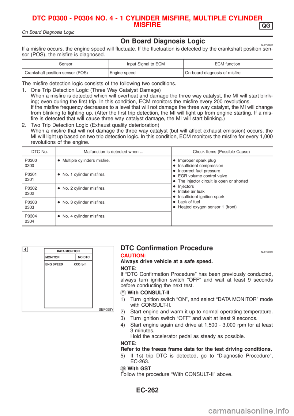
1) Turn ignition switch ªONº, and select ªDATA MONITORº mode
with CONSULT-II.
2) Start engine and warm it up to normal operating temperature.
3) Turn ignition switch ªOFFº and wait at least 9 seconds.
4) Start engine again and drive at 1,500 - 3,000 rpm for at least
3 minutes.
Hold the accelerator pedal as steady as possible.
NOTE:
Refer to the freeze frame data for the test driving conditions.
5) If 1st trip DTC is detected, go to ªDiagnostic Procedureº,
EC-263.
With GST
Follow the procedure ªWith CONSULT-IIº above.
DTC P0300 - P0304 NO.4-1CYLINDER MISFIRE, MULTIPLE CYLINDER
MISFIRE
QG
On Board Diagnosis Logic
EC-262
Page 564 of 2493

SEF598K
Component DescriptionNJEC0206The knock sensor is attached to the cylinder block. It senses
engine knocking using a piezoelectric element. A knocking vibration
from the cylinder block is sensed as vibrational pressure. This
pressure is converted into a voltage signal and sent to the ECM.
Freeze frame data will not be stored in the ECM for the knock
sensor. The MI will not light for knock sensor malfunction. The
knock sensor has one trip detection logic.
ECM Terminals and Reference ValueNJEC0207Specification data are reference values and are measured between each terminal and ground.
CAUTION:
Do not use ECM ground terminals when measuring input/output voltage. Doing so may result in dam-
age to the ECM's transistor. Use a ground other than ECM terminals, such as the ground.
TERMI-
NAL
NO.WIRE
COLORITEM CONDITION DATA (DC Voltage)
81 W Knock sensor[Engine is running]
+Idle speed1.0 - 4.0V
On Board Diagnosis LogicNJEC0208
DTC No. Malfunction is detected when ... Check Items (Possible Cause)
P0325
0325+An excessively low or high voltage from the knock sen-
sor is sent to ECM.+Harness or connectors
(The knock sensor circuit is open or shorted.)
+Knock sensor
SEF058Y
DTC Confirmation ProcedureNJEC0209NOTE:
If ªDTC Confirmation Procedureº has been previously conducted,
always turn ignition switch ªOFFº and wait at least 9 seconds
before conducting the next test.
TESTING CONDITION:
Before performing the following procedure, confirm that bat-
tery voltage is more than 10V at idle.
With CONSULT-II
1) Turn ignition switch ªONº and select ªDATA MONITORº mode
with CONSULT-II.
2) Start engine and run it for at least 5 seconds at idle speed.
3) If DTC is detected, go to ªDiagnostic Procedureº, EC-270.
With GST
Follow the procedure ªWith CONSULT-IIº above.
DTC P0325 KNOCK SENSOR (KS)QG
Component Description
EC-268
Page 613 of 2493
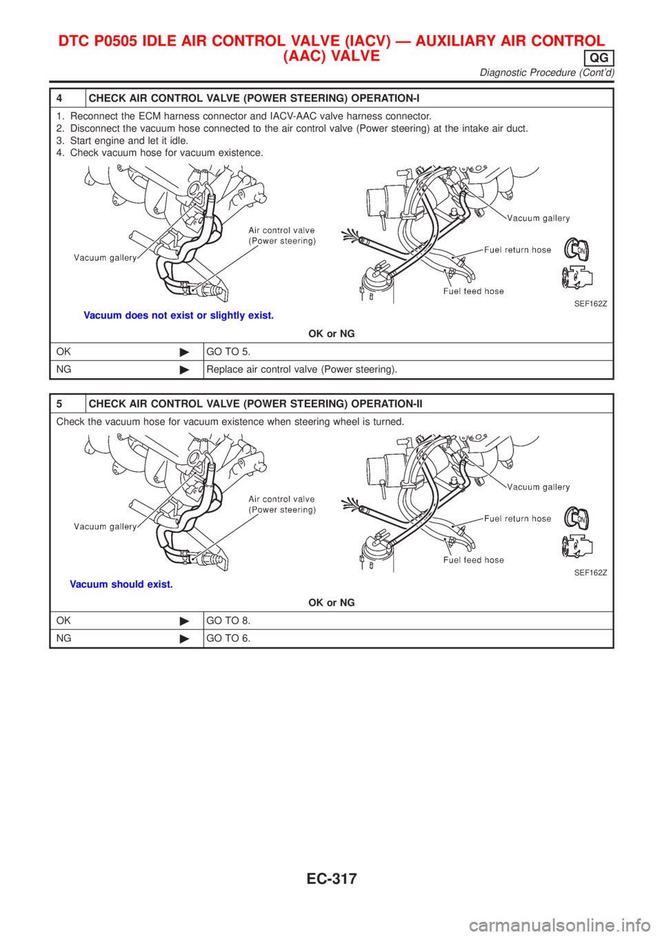
4 CHECK AIR CONTROL VALVE (POWER STEERING) OPERATION-I
1. Reconnect the ECM harness connector and IACV-AAC valve harness connector.
2. Disconnect the vacuum hose connected to the air control valve (Power steering) at the intake air duct.
3. Start engine and let it idle.
4. Check vacuum hose for vacuum existence.
SEF162Z
Vacuum does not exist or slightly exist.
OK or NG
OK©GO TO 5.
NG©Replace air control valve (Power steering).
5 CHECK AIR CONTROL VALVE (POWER STEERING) OPERATION-II
Check the vacuum hose for vacuum existence when steering wheel is turned.
SEF162Z
Vacuum should exist.
OK or NG
OK©GO TO 8.
NG©GO TO 6.
DTC P0505 IDLE AIR CONTROL VALVE (IACV) Ð AUXILIARY AIR CONTROL
(AAC) VALVE
QG
Diagnostic Procedure (Cont'd)
EC-317
Page 617 of 2493

SEF505V
Component DescriptionNJEC0287A closed throttle position switch and wide open throttle position
switch are built into the throttle position sensor unit. The wide open
throttle position switch is used only for A/T control.
When the throttle valve is in the closed position, the closed throttle
position switch sends a voltage signal to the ECM. The ECM only
uses this signal to open or close the EVAP canister purge control
valve when the throttle position sensor is malfunctioning.
CONSULT-II Reference Value in Data Monitor
Mode
NJEC0571Specification data are reference values.
MONITOR ITEM CONDITION SPECIFICATION
CLSD THL/P SW+Engine: IdleThrottle valve: Idle position ON
Throttle valve: Slightly open OFF
ECM Terminals and Reference ValueNJEC0288Specification data are reference values and are measured between each terminal and ground.
CAUTION:
Do not use ECM ground terminals when measuring input/output voltage. Doing so may result in dam-
age to the ECM's transistor. Use a ground other than ECM terminals, such as the ground.
TER-
MINAL
NO.WIRE
COLORITEM CONDITION DATA (DC Voltage)
40 Y/PUThrottle position switch
(Closed position)[Engine is running]
+Accelerator pedal releasedBATTERY VOLTAGE
(11 - 14V)
[Engine is running]
+Accelerator pedal depressedApproximately 0V
On Board Diagnosis LogicNJEC0289
DTC No. Malfunction is detected when ... Check Items (Possible Cause)
P0510
0510+Battery voltage from the closed throttle position switch is
sent to ECM with the throttle valve opened.+Harness or connectors
(The closed throttle position switch circuit is
shorted.)
+Closed throttle position switch
+Throttle position sensor
SEF197Y
DTC Confirmation ProcedureNJEC0290CAUTION:
Always drive vehicle at a safe speed.
NOTE:
If ªDTC Confirmation Procedureº has been previously conducted,
always turn ignition switch ªOFFº and wait at least 9 seconds
before conducting the next test.
With CONSULT-II
1) Start engine and warm it up to normal operating temperature.
2) Turn ignition switch ªOFFº, wait at least 9 seconds and then
start engine.
DTC P0510 CLOSED THROTTLE POSITION SWITCH (WHERE FITTED)QG
Component Description
EC-321
Page 618 of 2493
3) Select ªCLSD THL/P SWº in ªDATA MONITORº mode. If
ªCLSD THL/P SWº is not available, go to step 5.
4) Check the signal under the following conditions.
Condition Signal indication
Throttle valve: Idle position ON
Throttle valve: Slightly open OFF
If the result is NG, go to ªDiagnostic Procedureº, EC-324.
If OK, go to following step.
5) Select ªDATA MONITORº mode with CONSULT-II.
6) Drive the vehicle for at least 5 consecutive seconds under the
following condition.
THRTL POS SEN More than 2.3V
VHCL SPEED SE More than 4 km/h (2 MPH)
Selector lever Suitable position
Driving pattern Driving vehicle uphill (Increased engine load)
will help maintain the driving conditions
required for this test.
7) If 1st trip DTC is detected, go to ªDiagnostic Procedureº,
EC-324.
SEF090X
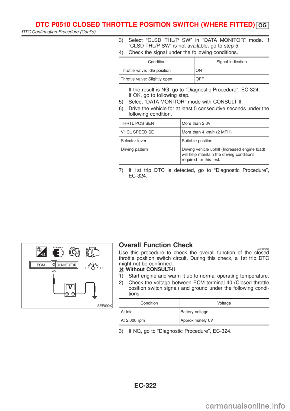
Overall Function CheckNJEC0291Use this procedure to check the overall function of the closed
throttle position switch circuit. During this check, a 1st trip DTC
might not be confirmed.
Without CONSULT-II
1) Start engine and warm it up to normal operating temperature.
2) Check the voltage between ECM terminal 40 (Closed throttle
position switch signal) and ground under the following condi-
tions.
Condition Voltage
At idle Battery voltage
At 2,000 rpm Approximately 0V
3) If NG, go to ªDiagnostic Procedureº, EC-324.
DTC P0510 CLOSED THROTTLE POSITION SWITCH (WHERE FITTED)QG
DTC Confirmation Procedure (Cont'd)
EC-322
Page 718 of 2493
3 DETECT MALFUNCTIONING PART
Check the following.
+15A fuse
+Harness connectors E75, F36 (If so equipped)
+Harness for open or short between fuse and ECM relay
+ECM relay
+Harness for open or short between IACV-AAC and ECM relay.
©Repair harness or connectors, or replace fuse or ECM relay.
4 CHECK OUTPUT SIGNAL CIRCUIT
1. Turn ignition switch ªOFFº.
2. Disconnect ECM harness connector.
3. Check harness continuity between
ECM terminal 6 and IACV-AAC valve terminal 1,
ECM terminal 7 and IACV-AAC valve terminal 4,
ECM terminal 15 and IACV-AAC valve terminal 3,
ECM terminal 16 and IACV-AAC valve terminal 6.
Refer to wiring diagram.
Continuity should exist.
4. Also check harness for short to ground and short to power.
OK or NG
OK©GO TO 5.
NG©Repair open circuit or short to ground or short to power in harness or connectors.
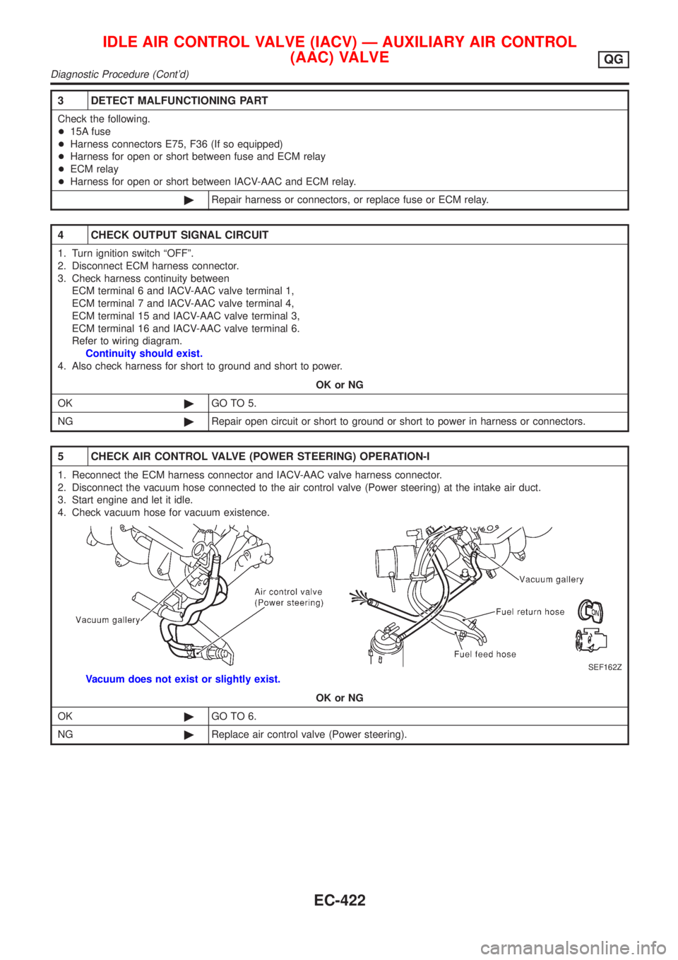
5 CHECK AIR CONTROL VALVE (POWER STEERING) OPERATION-I
1. Reconnect the ECM harness connector and IACV-AAC valve harness connector.
2. Disconnect the vacuum hose connected to the air control valve (Power steering) at the intake air duct.
3. Start engine and let it idle.
4. Check vacuum hose for vacuum existence.
SEF162Z
Vacuum does not exist or slightly exist.
OK or NG
OK©GO TO 6.
NG©Replace air control valve (Power steering).
IDLE AIR CONTROL VALVE (IACV) Ð AUXILIARY AIR CONTROL
(AAC) VALVE
QG
Diagnostic Procedure (Cont'd)
EC-422
Page 781 of 2493
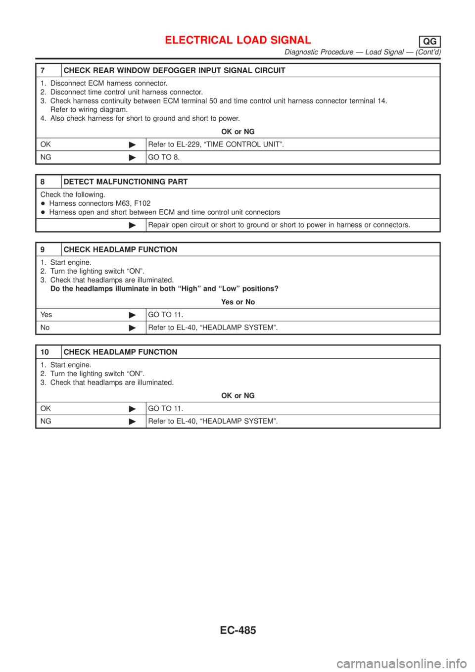
7 CHECK REAR WINDOW DEFOGGER INPUT SIGNAL CIRCUIT
1. Disconnect ECM harness connector.
2. Disconnect time control unit harness connector.
3. Check harness continuity between ECM terminal 50 and time control unit harness connector terminal 14.
Refer to wiring diagram.
4. Also check harness for short to ground and short to power.
OK or NG
OK©Refer to EL-229, ªTIME CONTROL UNITº.
NG©GO TO 8.
8 DETECT MALFUNCTIONING PART
Check the following.
+Harness connectors M63, F102
+Harness open and short between ECM and time control unit connectors
©Repair open circuit or short to ground or short to power in harness or connectors.
9 CHECK HEADLAMP FUNCTION
1. Start engine.
2. Turn the lighting switch ªONº.
3. Check that headlamps are illuminated.
Do the headlamps illuminate in both ªHighº and ªLowº positions?
YesorNo
Ye s©GO TO 11.
No©Refer to EL-40, ªHEADLAMP SYSTEMº.
10 CHECK HEADLAMP FUNCTION
1. Start engine.
2. Turn the lighting switch ªONº.
3. Check that headlamps are illuminated.
OK or NG
OK©GO TO 11.
NG©Refer to EL-40, ªHEADLAMP SYSTEMº.
ELECTRICAL LOAD SIGNALQG
Diagnostic Procedure Ð Load Signal Ð (Cont'd)
EC-485