2001 NISSAN ALMERA N16 check engine light
[x] Cancel search: check engine lightPage 782 of 2493
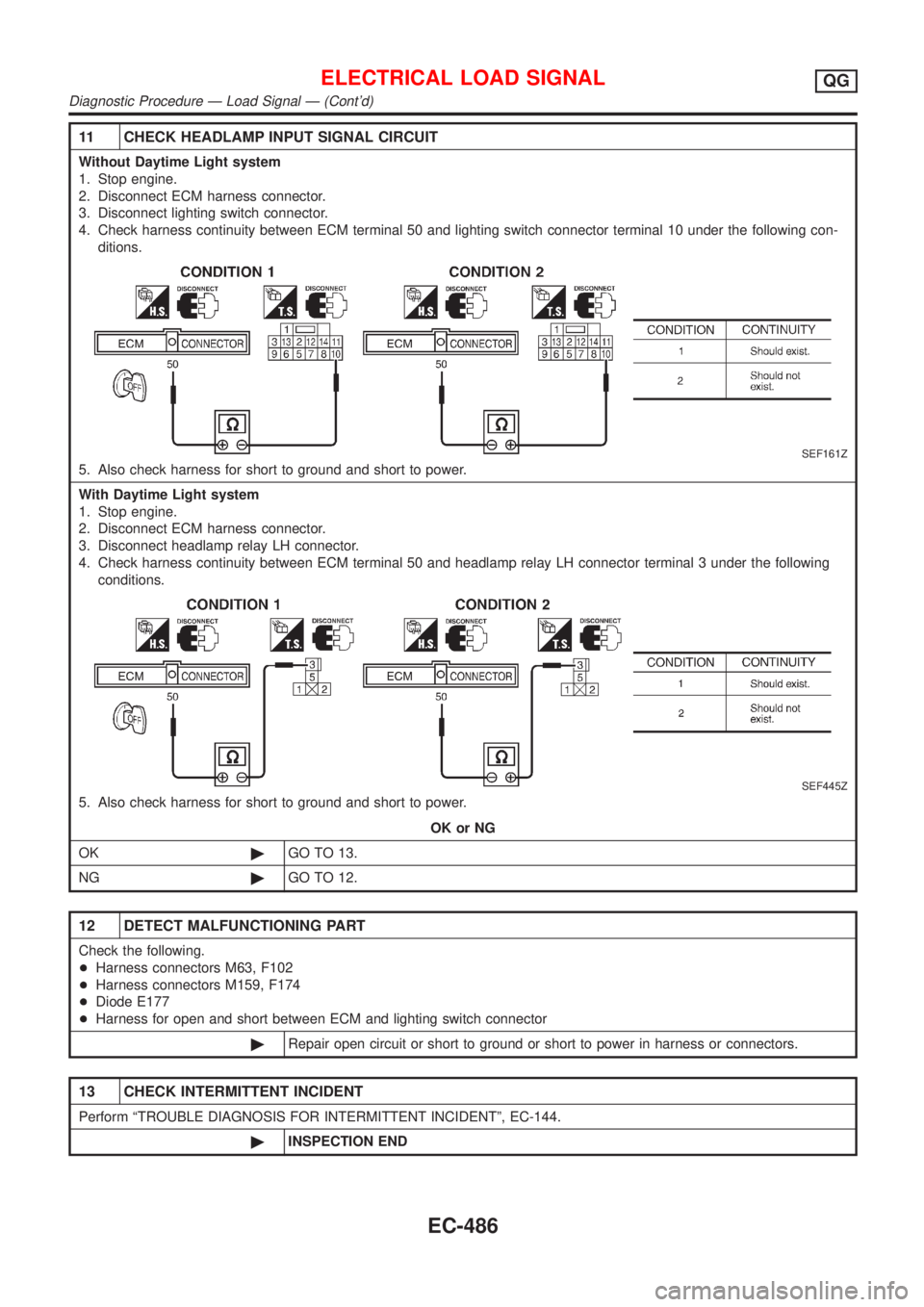
11 CHECK HEADLAMP INPUT SIGNAL CIRCUIT
Without Daytime Light system
1. Stop engine.
2. Disconnect ECM harness connector.
3. Disconnect lighting switch connector.
4. Check harness continuity between ECM terminal 50 and lighting switch connector terminal 10 under the following con-
ditions.
SEF161Z
5. Also check harness for short to ground and short to power.
With Daytime Light system
1. Stop engine.
2. Disconnect ECM harness connector.
3. Disconnect headlamp relay LH connector.
4. Check harness continuity between ECM terminal 50 and headlamp relay LH connector terminal 3 under the following
conditions.
SEF445Z
5. Also check harness for short to ground and short to power.
OK or NG
OK©GO TO 13.
NG©GO TO 12.
12 DETECT MALFUNCTIONING PART
Check the following.
+Harness connectors M63, F102
+Harness connectors M159, F174
+Diode E177
+Harness for open and short between ECM and lighting switch connector
©Repair open circuit or short to ground or short to power in harness or connectors.
13 CHECK INTERMITTENT INCIDENT
Perform ªTROUBLE DIAGNOSIS FOR INTERMITTENT INCIDENTº, EC-144.
©INSPECTION END
ELECTRICAL LOAD SIGNALQG
Diagnostic Procedure Ð Load Signal Ð (Cont'd)
EC-486
Page 819 of 2493
+Erasing the emission-related diagnostic information using CONSULT-II is easier and quicker than
switching the diagnostic test mode using the data link connector.
Malfunction Indicator (MI)
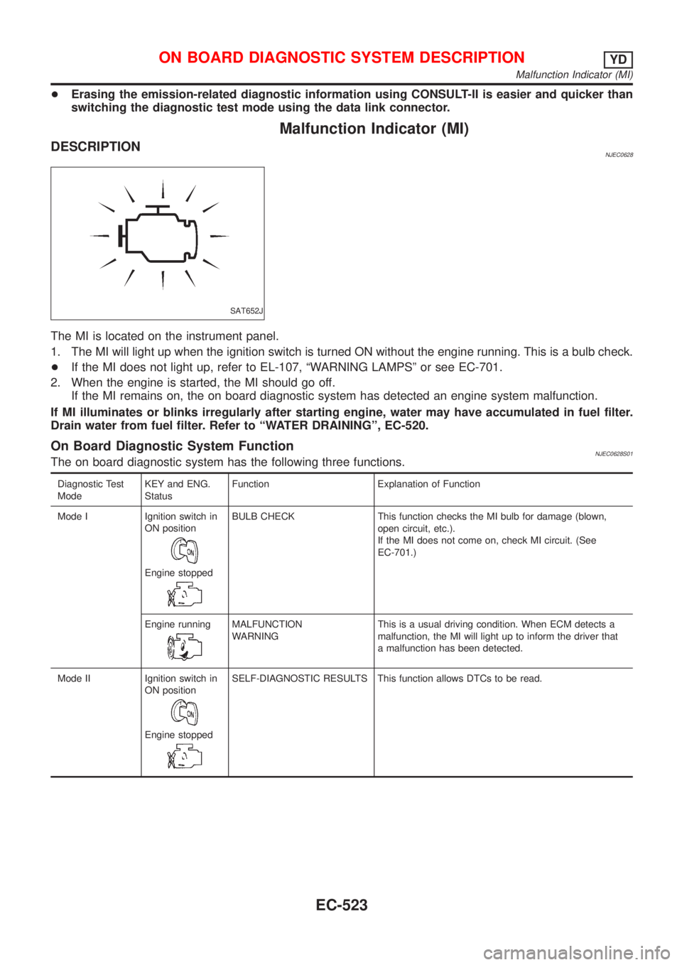
DESCRIPTIONNJEC0628
SAT652J
The MI is located on the instrument panel.
1. The MI will light up when the ignition switch is turned ON without the engine running. This is a bulb check.
+If the MI does not light up, refer to EL-107, ªWARNING LAMPSº or see EC-701.
2. When the engine is started, the MI should go off.
If the MI remains on, the on board diagnostic system has detected an engine system malfunction.
If MI illuminates or blinks irregularly after starting engine, water may have accumulated in fuel filter.
Drain water from fuel filter. Refer to ªWATER DRAININGº, EC-520.
On Board Diagnostic System FunctionNJEC0628S01The on board diagnostic system has the following three functions.
Diagnostic Test
ModeKEY and ENG.
StatusFunction Explanation of Function
Mode I Ignition switch in
ON position
Engine stopped
BULB CHECK This function checks the MI bulb for damage (blown,
open circuit, etc.).
If the MI does not come on, check MI circuit. (See
EC-701.)
Engine running
MALFUNCTION
WARNINGThis is a usual driving condition. When ECM detects a
malfunction, the MI will light up to inform the driver that
a malfunction has been detected.
Mode II Ignition switch in
ON position
Engine stopped
SELF-DIAGNOSTIC RESULTS This function allows DTCs to be read.
ON BOARD DIAGNOSTIC SYSTEM DESCRIPTIONYD
Malfunction Indicator (MI)
EC-523
Page 832 of 2493
Basic InspectionNJEC0632Precaution:
Perform Basic Inspection without electrical or mechanical
loads applied;
+Headlamp switch is OFF,
+On vehicles equipped with daytime light systems, set
lighting switch to the 1st position to light only small
lamps.
+Air conditioner switch is OFF,
+Rear defogger switch is OFF,
+Steering wheel is in the straight-ahead position, etc.
1 INSPECTION START
1. Check service records for any recent repairs that may indicate a related problem.
2. Check the current need for scheduled maintenance, especially for fuel filter and air cleaner filter. Refer to MA-4, ªPeri-
odic Maintenanceº.
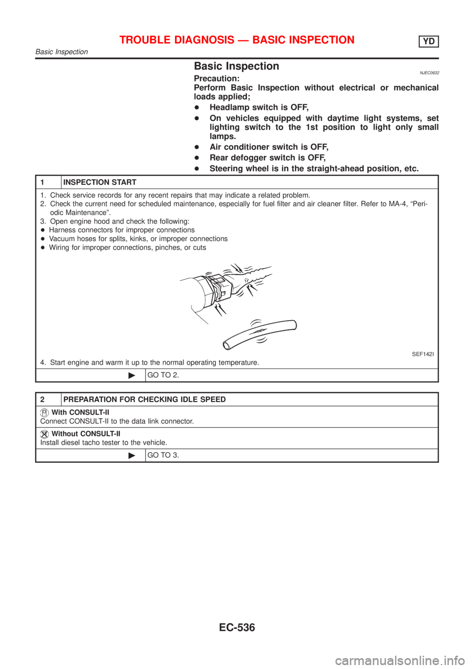
3. Open engine hood and check the following:
+Harness connectors for improper connections
+Vacuum hoses for splits, kinks, or improper connections
+Wiring for improper connections, pinches, or cuts
SEF142I
4. Start engine and warm it up to the normal operating temperature.
©GO TO 2.
2 PREPARATION FOR CHECKING IDLE SPEED
With CONSULT-II
Connect CONSULT-II to the data link connector.
Without CONSULT-II
Install diesel tacho tester to the vehicle.
©GO TO 3.
TROUBLE DIAGNOSIS Ð BASIC INSPECTIONYD
Basic Inspection
EC-536
Page 1049 of 2493
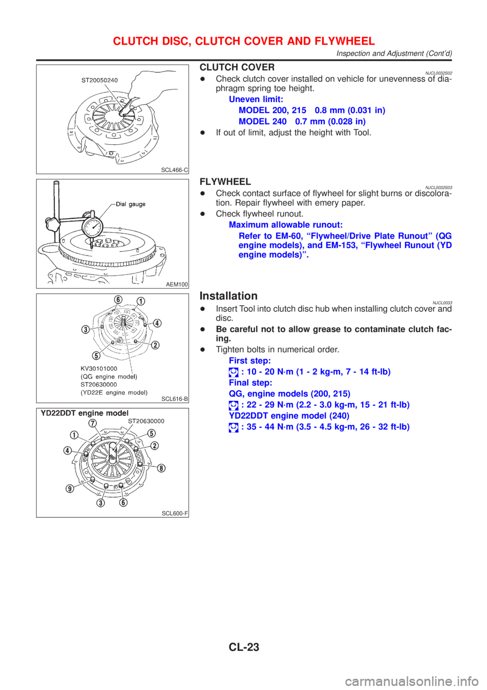
SCL466-C
CLUTCH COVERNJCL0032S02+Check clutch cover installed on vehicle for unevenness of dia-
phragm spring toe height.
Uneven limit:
MODEL 200, 215 0.8 mm (0.031 in)
MODEL 240 0.7 mm (0.028 in)
+If out of limit, adjust the height with Tool.
AEM100
FLYWHEELNJCL0032S03+Check contact surface of flywheel for slight burns or discolora-
tion. Repair flywheel with emery paper.
+Check flywheel runout.
Maximum allowable runout:
Refer to EM-60, ªFlywheel/Drive Plate Runoutº (QG
engine models), and EM-153, ªFlywheel Runout (YD
engine models)º.
SCL616-B
SCL600-F
InstallationNJCL0033+Insert Tool into clutch disc hub when installing clutch cover and
disc.
+Be careful not to allow grease to contaminate clutch fac-
ing.
+Tighten bolts in numerical order.
First step:
: 10 - 20 N´m (1 - 2 kg-m,7-14ft-lb)
Final step:
QG, engine models (200, 215)
: 22 - 29 N´m (2.2 - 3.0 kg-m, 15 - 21 ft-lb)
YD22DDT engine model (240)
: 35 - 44 N´m (3.5 - 4.5 kg-m, 26 - 32 ft-lb)
CLUTCH DISC, CLUTCH COVER AND FLYWHEEL
Inspection and Adjustment (Cont'd)
CL-23
Page 1189 of 2493
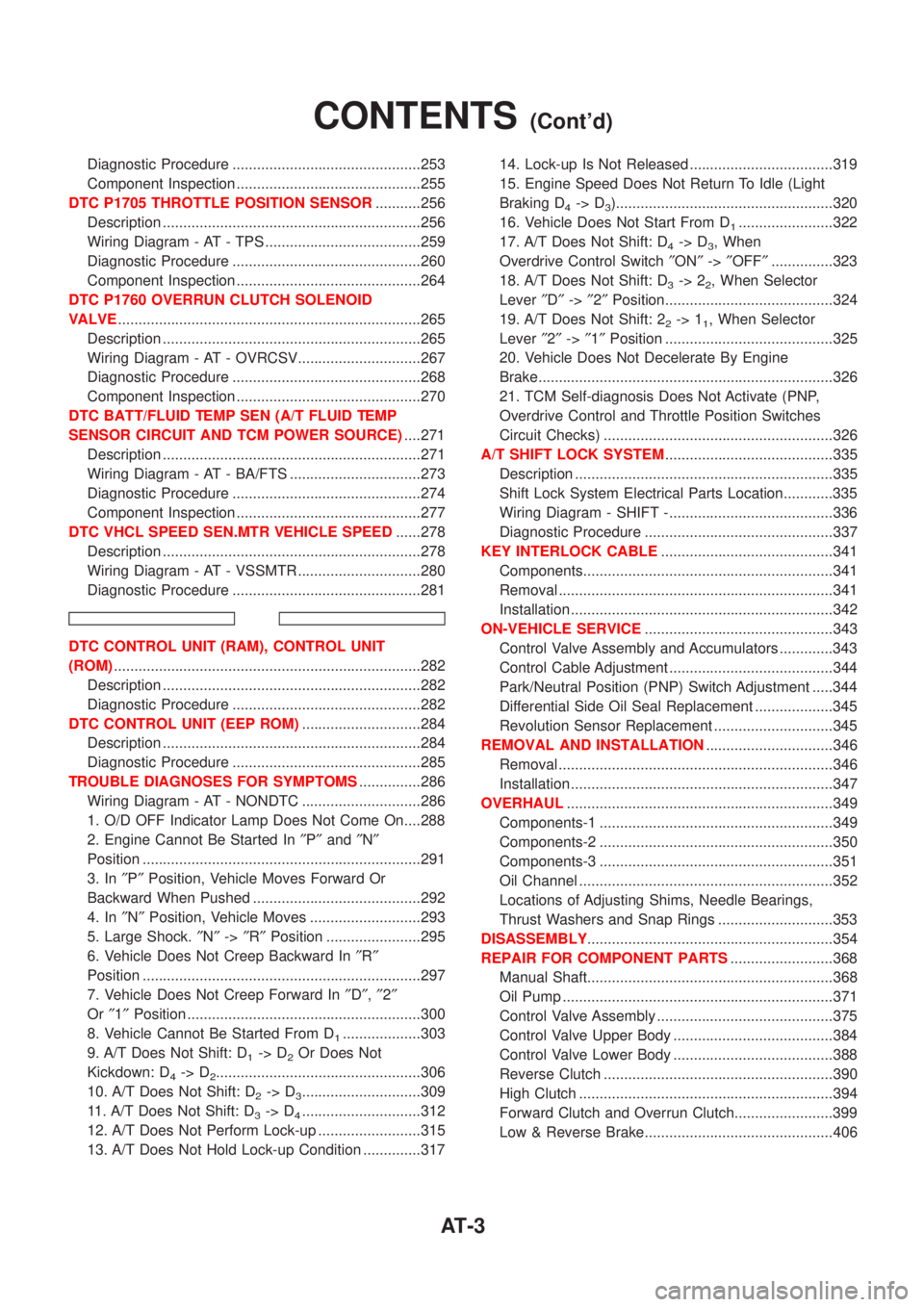
Diagnostic Procedure ..............................................253
Component Inspection .............................................255
DTC P1705 THROTTLE POSITION SENSOR...........256
Description ...............................................................256
Wiring Diagram - AT - TPS ......................................259
Diagnostic Procedure ..............................................260
Component Inspection .............................................264
DTC P1760 OVERRUN CLUTCH SOLENOID
VALVE..........................................................................265
Description ...............................................................265
Wiring Diagram - AT - OVRCSV..............................267
Diagnostic Procedure ..............................................268
Component Inspection .............................................270
DTC BATT/FLUID TEMP SEN (A/T FLUID TEMP
SENSOR CIRCUIT AND TCM POWER SOURCE)....271
Description ...............................................................271
Wiring Diagram - AT - BA/FTS ................................273
Diagnostic Procedure ..............................................274
Component Inspection .............................................277
DTC VHCL SPEED SEN.MTR VEHICLE SPEED......278
Description ...............................................................278
Wiring Diagram - AT - VSSMTR ..............................280
Diagnostic Procedure ..............................................281
DTC CONTROL UNIT (RAM), CONTROL UNIT
(ROM)...........................................................................282
Description ...............................................................282
Diagnostic Procedure ..............................................282
DTC CONTROL UNIT (EEP ROM).............................284
Description ...............................................................284
Diagnostic Procedure ..............................................285
TROUBLE DIAGNOSES FOR SYMPTOMS...............286
Wiring Diagram - AT - NONDTC .............................286
1. O/D OFF Indicator Lamp Does Not Come On....288
2. Engine Cannot Be Started In²P²and²N²
Position ....................................................................291
3. In²P²Position, Vehicle Moves Forward Or
Backward When Pushed .........................................292
4. In²N²Position, Vehicle Moves ...........................293
5. Large Shock.²N²->²R²Position .......................295
6. Vehicle Does Not Creep Backward In²R²
Position ....................................................................297
7. Vehicle Does Not Creep Forward In²D²,²2²
Or²1²Position .........................................................300
8. Vehicle Cannot Be Started From D
1...................303
9. A/T Does Not Shift: D
1-> D2Or Does Not
Kickdown: D
4-> D2..................................................306
10. A/T Does Not Shift: D
2-> D3.............................309
11. A/T Does Not Shift: D
3-> D4.............................312
12. A/T Does Not Perform Lock-up .........................315
13. A/T Does Not Hold Lock-up Condition ..............31714. Lock-up Is Not Released ...................................319
15. Engine Speed Does Not Return To Idle (Light
Braking D
4-> D3).....................................................320
16. Vehicle Does Not Start From D
1.......................322
17. A/T Does Not Shift: D
4-> D3, When
Overdrive Control Switch²ON²->²OFF²...............323
18. A/T Does Not Shift: D
3-> 22, When Selector
Lever²D²->²2²Position.........................................324
19. A/T Does Not Shift: 2
2-> 11, When Selector
Lever²2²->²1²Position .........................................325
20. Vehicle Does Not Decelerate By Engine
Brake........................................................................326
21. TCM Self-diagnosis Does Not Activate (PNP,
Overdrive Control and Throttle Position Switches
Circuit Checks) ........................................................326
A/T SHIFT LOCK SYSTEM.........................................335
Description ...............................................................335
Shift Lock System Electrical Parts Location............335
Wiring Diagram - SHIFT -........................................336
Diagnostic Procedure ..............................................337
KEY INTERLOCK CABLE..........................................341
Components.............................................................341
Removal ...................................................................341
Installation ................................................................342
ON-VEHICLE SERVICE..............................................343
Control Valve Assembly and Accumulators .............343
Control Cable Adjustment ........................................344
Park/Neutral Position (PNP) Switch Adjustment .....344
Differential Side Oil Seal Replacement ...................345
Revolution Sensor Replacement .............................345
REMOVAL AND INSTALLATION...............................346
Removal ...................................................................346
Installation ................................................................347
OVERHAUL.................................................................349
Components-1 .........................................................349
Components-2 .........................................................350
Components-3 .........................................................351
Oil Channel ..............................................................352
Locations of Adjusting Shims, Needle Bearings,
Thrust Washers and Snap Rings ............................353
DISASSEMBLY............................................................354
REPAIR FOR COMPONENT PARTS.........................368
Manual Shaft............................................................368
Oil Pump ..................................................................371
Control Valve Assembly ...........................................375
Control Valve Upper Body .......................................384
Control Valve Lower Body .......................................388
Reverse Clutch ........................................................390
High Clutch ..............................................................394
Forward Clutch and Overrun Clutch........................399
Low & Reverse Brake..............................................406
CONTENTS(Cont'd)
AT-3
Page 1238 of 2493
SAT964I
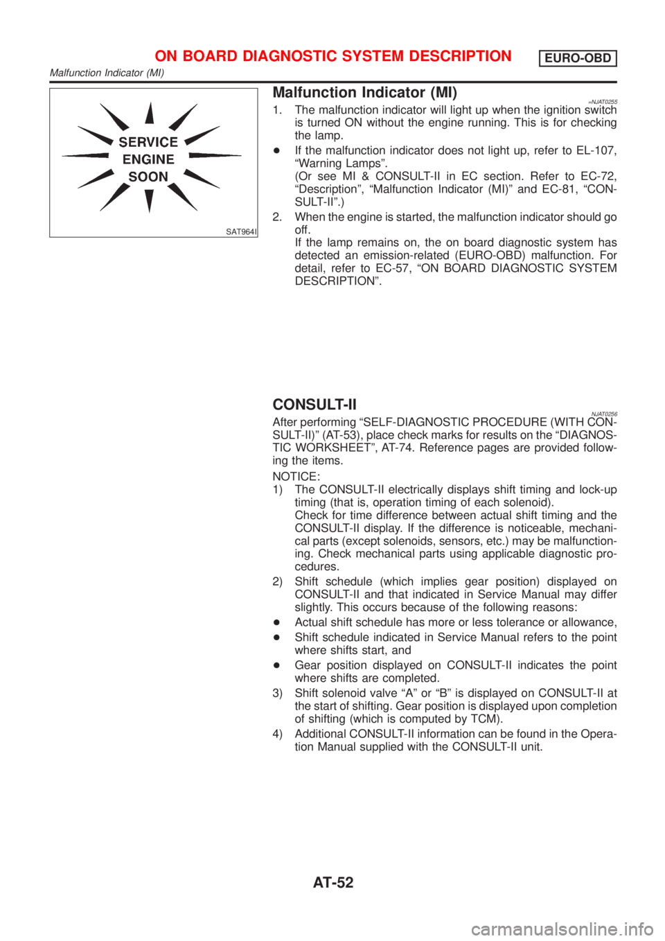
Malfunction Indicator (MI)=NJAT02551. The malfunction indicator will light up when the ignition switch
is turned ON without the engine running. This is for checking
the lamp.
+If the malfunction indicator does not light up, refer to EL-107,
ªWarning Lampsº.
(Or see MI & CONSULT-II in EC section. Refer to EC-72,
ªDescriptionº, ªMalfunction Indicator (MI)º and EC-81, ªCON-
SULT-IIº.)
2. When the engine is started, the malfunction indicator should go
off.
If the lamp remains on, the on board diagnostic system has
detected an emission-related (EURO-OBD) malfunction. For
detail, refer to EC-57, ªON BOARD DIAGNOSTIC SYSTEM
DESCRIPTIONº.
CONSULT-IINJAT0256After performing ªSELF-DIAGNOSTIC PROCEDURE (WITH CON-
SULT-II)º (AT-53), place check marks for results on the ªDIAGNOS-
TIC WORKSHEETº, AT-74. Reference pages are provided follow-
ing the items.
NOTICE:
1) The CONSULT-II electrically displays shift timing and lock-up
timing (that is, operation timing of each solenoid).
Check for time difference between actual shift timing and the
CONSULT-II display. If the difference is noticeable, mechani-
cal parts (except solenoids, sensors, etc.) may be malfunction-
ing. Check mechanical parts using applicable diagnostic pro-
cedures.
2) Shift schedule (which implies gear position) displayed on
CONSULT-II and that indicated in Service Manual may differ
slightly. This occurs because of the following reasons:
+Actual shift schedule has more or less tolerance or allowance,
+Shift schedule indicated in Service Manual refers to the point
where shifts start, and
+Gear position displayed on CONSULT-II indicates the point
where shifts are completed.
3) Shift solenoid valve ªAº or ªBº is displayed on CONSULT-II at
the start of shifting. Gear position is displayed upon completion
of shifting (which is computed by TCM).
4) Additional CONSULT-II information can be found in the Opera-
tion Manual supplied with the CONSULT-II unit.
ON BOARD DIAGNOSTIC SYSTEM DESCRIPTIONEURO-OBD
Malfunction Indicator (MI)
AT-52
Page 1256 of 2493
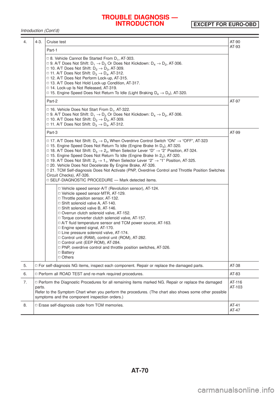
4. 4-3. Cruise testAT-90
AT-93
Part-1
N8. Vehicle Cannot Be Started From D
1, AT-303.
N9. A/T Does Not Shift: D
1®D2Or Does Not Kickdown: D4®D2, AT-306.
N10. A/T Does Not Shift: D
2®D3, AT-309.
N11. A/T Does Not Shift: D
3®D4, AT-312.
N12. A/T Does Not Perform Lock-up, AT-315.
N13. A/T Does Not Hold Lock-up Condition, AT-317.
N14. Lock-up Is Not Released, AT-319.
N15. Engine Speed Does Not Return To Idle (Light Braking D
4®D3), AT-320.
Part-2AT-97
N16. Vehicle Does Not Start From D
1, AT-322.
N9. A/T Does Not Shift: D
1®D2Or Does Not Kickdown: D4®D2, AT-306.
N10. A/T Does Not Shift: D
2®D3, AT-309.
N11. A/T Does Not Shift: D
3®D4, AT-312.
Part-3AT-99
N17. A/T Does Not Shift: D
4®D3When Overdrive Control Switch ªONº®ªOFFº, AT-323
N15. Engine Speed Does Not Return To Idle (Engine Brake In D
3), AT-320.
N18. A/T Does Not Shift: D
3®22, When Selector Lever ªDº®ª2º Position, AT-324.
N15. Engine Speed Does Not Return To Idle (Engine Brake In 2
2), AT-320.
N19. A/T Does Not Shift: 2
2®11, When Selector Lever ª2º®ª1º Position, AT-325.
N20. Vehicle Does Not Decelerate By Engine Brake, AT-326.
N21. TCM Self-diagnosis Does Not Activate (PNP, Overdrive Control and Throttle Position Switches
Circuit Checks), AT-326.
NSELF-DIAGNOSTIC PROCEDURE Ð Mark detected items.
NVehicle speed sensor´A/T (Revolution sensor), AT-124.
NVehicle speed sensor´MTR, AT-129.
NThrottle position sensor, AT-132.
NShift solenoid valve A, AT-140.
NShift solenoid valve B, AT-146.
NOverrun clutch solenoid valve, AT-152.
NTorque converter clutch solenoid valve, AT-157.
NA/T fluid temperature sensor and TCM power source, AT-163.
NEngine speed signal, AT-170.
NLine pressure solenoid valve, AT-174.
NControl unit (RAM), control unit (ROM), AT-282.
NControl unit (EEP ROM), AT-284.
NPNP, overdrive control and throttle position switches, AT-326.
NBattery
NOthers
5.NFor self-diagnosis NG items, inspect each component. Repair or replace the damaged parts. AT-38
6.NPerform all ROAD TEST and re-mark required procedures. AT-83
7.NPerform the Diagnostic Procedures for all remaining items marked NG. Repair or replace the damaged
parts.
Refer to the Symptom Chart when you perform the procedures. (The chart also shows some other possible
symptoms and the component inspection orders.)AT-116
AT-103
8.NErase self-diagnosis code from TCM memories. AT-41
AT-47
TROUBLE DIAGNOSIS Ð
INTRODUCTION
EXCEPT FOR EURO-OBD
Introduction (Cont'd)
AT-70
Page 1261 of 2493
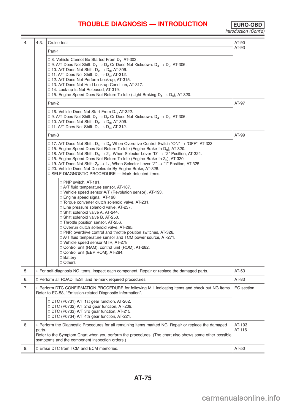
4. 4-3. Cruise testAT-90
AT-93
Part-1
N8. Vehicle Cannot Be Started From D
1, AT-303.
N9. A/T Does Not Shift: D
1®D2Or Does Not Kickdown: D4®D2, AT-306.
N10. A/T Does Not Shift: D
2®D3, AT-309.
N11. A/T Does Not Shift: D
3®D4, AT-312.
N12. A/T Does Not Perform Lock-up, AT-315.
N13. A/T Does Not Hold Lock-up Condition, AT-317.
N14. Lock-up Is Not Released, AT-319.
N15. Engine Speed Does Not Return To Idle (Light Braking D
4®D3), AT-320.
Part-2AT-97
N16. Vehicle Does Not Start From D
1, AT-322.
N9. A/T Does Not Shift: D
1®D2Or Does Not Kickdown: D4®D2, AT-306.
N10. A/T Does Not Shift: D
2®D3, AT-309.
N11. A/T Does Not Shift: D
3®D4, AT-312.
Part-3AT-99
N17. A/T Does Not Shift: D
4®D3When Overdrive Control Switch ªONº®ªOFFº, AT-323
N15. Engine Speed Does Not Return To Idle (Engine Brake In D
3), AT-320.
N18. A/T Does Not Shift: D
3®22, When Selector Lever ªDº®ª2º Position, AT-324.
N15. Engine Speed Does Not Return To Idle (Engine Brake In 2
2), AT-320.
N19. A/T Does Not Shift: 2
2®11, When Selector Lever ª2º®ª1º Position, AT-325.
N20. Vehicle Does Not Decelerate By Engine Brake, AT-326.
NSELF-DIAGNOSTIC PROCEDURE Ð Mark detected items.
NPNP switch, AT-181.
NA/T fluid temperature sensor, AT-187.
NVehicle speed sensor´A/T (Revolution sensor), AT-193.
NEngine speed signal, AT-198.
NTorque converter clutch solenoid valve, AT-231.
NLine pressure solenoid valve, AT-237.
NShift solenoid valve A, AT-244.
NShift solenoid valve B, AT-250.
NThrottle position sensor, AT-256.
NOverrun clutch solenoid valve, AT-265.
NPNP, overdrive control and throttle position switches, AT-326.
NA/T fluid temperature sensor and TCM power source, AT-271.
NVehicle speed sensor´MTR, AT-278.
NControl unit (RAM), control unit (ROM), AT-282.
NControl unit (EEP ROM), AT-284.
NBattery
NOthers
5.NFor self-diagnosis NG items, inspect each component. Repair or replace the damaged parts. AT-53
6.NPerform all ROAD TEST and re-mark required procedures. AT-83
7.NPerform DTC CONFIRMATION PROCEDURE for following MIL indicating items and check out NG items.
Refer to EC-58, ªEmission-related Diagnostic Informationº.EC section
NDTC (P0731) A/T 1st gear function, AT-202.
NDTC (P0732) A/T 2nd gear function, AT-209.
NDTC (P0733) A/T 3rd gear function, AT-215.
NDTC (P0734) A/T 4th gear function, AT-221.
8.NPerform the Diagnostic Procedures for all remaining items marked NG. Repair or replace the damaged
parts.
Refer to the Symptom Chart when you perform the procedures. (The chart also shows some other possible
symptoms and the component inspection orders.)AT-103
AT-116
9.NErase DTC from TCM and ECM memories. AT-50
TROUBLE DIAGNOSIS Ð INTRODUCTIONEURO-OBD
Introduction (Cont'd)
AT-75