2001 NISSAN ALMERA N16 Resistor
[x] Cancel search: ResistorPage 2224 of 2493

NEL796
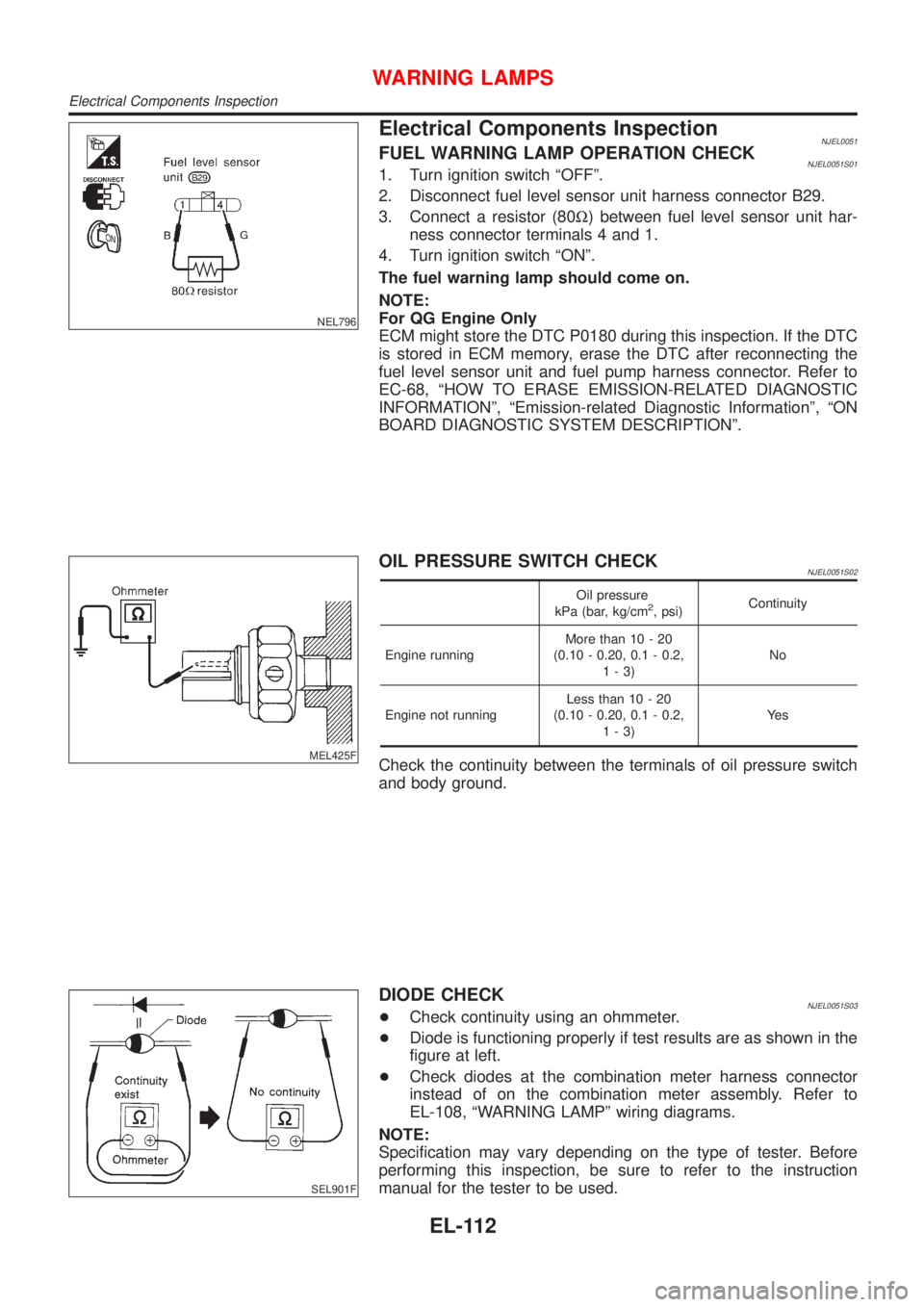
Electrical Components InspectionNJEL0051FUEL WARNING LAMP OPERATION CHECKNJEL0051S011. Turn ignition switch ªOFFº.
2. Disconnect fuel level sensor unit harness connector B29.
3. Connect a resistor (80W) between fuel level sensor unit har-
ness connector terminals 4 and 1.
4. Turn ignition switch ªONº.
The fuel warning lamp should come on.
NOTE:
For QG Engine Only
ECM might store the DTC P0180 during this inspection. If the DTC
is stored in ECM memory, erase the DTC after reconnecting the
fuel level sensor unit and fuel pump harness connector. Refer to
EC-68, ªHOW TO ERASE EMISSION-RELATED DIAGNOSTIC
INFORMATIONº, ªEmission-related Diagnostic Informationº, ªON
BOARD DIAGNOSTIC SYSTEM DESCRIPTIONº.
MEL425F
OIL PRESSURE SWITCH CHECKNJEL0051S02
Oil pressure
kPa (bar, kg/cm2, psi)Continuity
Engine runningMore than 10 - 20
(0.10 - 0.20, 0.1 - 0.2,
1-3)No
Engine not runningLess than 10 - 20
(0.10 - 0.20, 0.1 - 0.2,
1-3)Ye s
Check the continuity between the terminals of oil pressure switch
and body ground.
SEL901F
DIODE CHECKNJEL0051S03+Check continuity using an ohmmeter.
+Diode is functioning properly if test results are as shown in the
figure at left.
+Check diodes at the combination meter harness connector
instead of on the combination meter assembly. Refer to
EL-108, ªWARNING LAMPº wiring diagrams.
NOTE:
Specification may vary depending on the type of tester. Before
performing this inspection, be sure to refer to the instruction
manual for the tester to be used.
WARNING LAMPS
Electrical Components Inspection
EL-112
Page 2482 of 2493

A
A/C HFC134a (R134a) system precaution . HA-2
A/C HFC134a (R134a) system service
procedure .............................................. HA-84
A/C HFC134a (R134a) system service
tools ....................................................... HA-11
A/C HFC134a system service equip-
ment precaution ....................................... HA-6
A/C air flow ............................................... HA-20
A/C component layout .............................. HA-18
A/C compressor clutch removal and
installation .............................................. HA-89
A/C compressor precaution ........................ HA-5
A/C compressor special service tool .......... HA-9
A/C control linkage adjustment
(manual A/C) ......................................... HA-47
A/C control operation (manual A/C) .......... HA-19
A/C diagnostic work flow
(manual A/C) ......................................... HA-39
A/C harness layout (manual A/C) ............. HA-22
A/C lubricant (R134a) ............................... HA-86
A/C operational check ............................... HA-40
A/C performance chart .............................. HA-77
A/C performance test diagnoses .............. HA-75
A/C relay ................................................... HA-72
A/C service data specification ................ HA-103
A/C switch ................................................. HA-73
A/C, M - Wiring diagram ........................... HA-27
A/CCUT - Wiring diagram ....................... EC-700
A/T - Wiring diagram - AT - 1ST .............. AT-205
A/T - Wiring diagram - AT - 2ND ............. AT-212
A/T - Wiring diagram - AT - 3RD ............. AT-218
A/T - Wiring diagram - AT - 4TH .............. AT-225
A/T - Wiring diagram - AT - BA/FTS ....... AT-165,
273
A/T - Wiring diagram - AT - ENG SS ...... AT-171,
199
A/T - Wiring diagram - AT - FTS .............. AT-189
A/T - Wiring diagram - AT - LPSV ... AT-176, 239
A/T - Wiring diagram - AT - MAIN ........... AT-121
A/T - Wiring diagram - AT -
OVRCSV ...................................... AT-153, 267
A/T - Wiring diagram - AT - PNP/SW ...... AT-183
A/T - Wiring diagram - AT - SSV/A .. AT-142, 246
A/T - Wiring diagram - AT - SSV/B .. AT-148, 252
A/T - Wiring diagram - AT - TCV ..... AT-159, 233
A/T - Wiring diagram - AT - TPS ..... AT-134, 259
A/T - Wiring diagram - AT - VSS/AT ....... AT-126,
195
A/T - Wiring diagram - AT -
VSSMTR ...................................... AT-130, 280
A/T control ............................................... EC-437
A/T diagnosis communication line .......... EC-361
A/T fluid temperature sensor ................... AT-192
A/T shift lock system - Wiring
diagram ................................................ AT-336
A/T shift lock system ................................ AT-335
A/T trouble diagnoses .......................... AT-67, 72AAC/V - Wiring diagram ................. EC-315, 420
ABS (anti-lock brake system) ................... BR-49
ABS - Wiring diagram ............................... BR-54
ABS sensor rotor ....................................... AX-24
APS - Wiring diagram ............................. EC-577
ATDIAG - Wiring diagram ............... EC-362, 438
Accelerator control system .................... FE-3, 15
Accelerator position sensor .................... EC-577
Air bag disposal ........................................ RS-35
Air bag precautions ...................................... GI-3
Air bag ....................................................... RS-20
Air bleeding (hydraulic clutch) ................... CL-10
Air bleeding for brake system ..................... BR-8
Air conditioner cut control ................. EC-32, 507
Air flow meter - See Mass air flow
sensor .......................................... EC-152, 566
Air mix door control linkage
adjustment ............................................. HA-49
Air spoiler, rear .......................................... BT-47
Alternator ................................................... SC-27
Angular tightening application .............. EM-4, 76
Antenna - See Power antenna ................ EL-162
Anti-lock brake system - Wiring
diagram .................................................. BR-54
Audio and A/C control removal and
installation - See Instrument panel ........ BT-25
Audio ........................................................ EL-149
Automatic transaxle number ...................... GI-41
Auxiliary air control (AAC) valve ..... EC-313, 418
B
Back-up lamp switch (M/T) ....................... MT-21
Back-up lamp ............................................. EL-58
Ball joint (front) .......................................... SU-13
Basic inspection ................................ EC-98, 536
Battery ......................................................... SC-3
Baulk ring (M/T) ............................ MT-31, 55, 93
Blower motor ............................................. HA-60
Blower resistor .......................................... HA-60
Board-on lift ................................................ GI-44
Body alignment .......................................... BT-74
Brake booster ............................................ BR-20
Brake fluid change ...................................... BR-7
Brake fluid level and line check .................. BR-7
Brake hydraulic line .................................... BR-9
Brake pedal ............................................... BR-12
Bulb specifications ................................... EL-366
Bumper, front .............................................. BT-7
Bumper, rear .............................................. BT-10
C
CHARGE - Wiring diagram ....................... SC-25
CHIME - Wiring diagram .......................... EL-115
CIGAR - Wiring diagram ......................... EL-136
CKPS - Wiring diagram .......... EC-274, 395, 587
CMPS - Wiring diagram .......................... EC-280
ALPHABETICAL INDEX
IDX-2
Page 2483 of 2493

CONSULT for ABS .................................... BR-58
CONSULT for engine ........................ EC-81, 527
COOL/F - Wiring diagram ............... EC-337, 618
Camshaft inspection ......................... EM-36, 122
Camshaft position sensor (CMPS) ......... EC-278
Camshaft position sensor (PHASE) ........ EC-278
Canister - See EVAP canister ................... EC-33
Charging system ....................................... SC-24
Cigarette lighter ....................................... EL-136
Circuit breaker ........................................... EL-22
Closed throttle position switch ....... EC-321, 426
Clutch cover .............................................. CL-22
Clutch disc ................................................. CL-22
Clutch master cylinder ............................... CL-11
Clutch operating cylinder ........................... CL-14
Clutch pedal .............................................. CL-10
Clutch release bearing ........................ CL-17, 20
Clutch release mechanism .................. CL-17, 20
Clutch withdrawal lever ....................... CL-17, 20
Coil spring (front) ........................................ SU-9
Coil spring (rear) ....................................... SU-21
Collision diagnosis .................................... RS-71
Combination lamp, rear, removal and
installation .............................................. BT-47
Combination meter removal and instal-
lation - See Instrument panel ................ BT-25
Combination meter .................................... EL-89
Combination switch ................................... EL-37
Compression pressure ............................. EM-82
Compressor clutch removal and
installation .............................................. HA-89
Compressor precaution ............................... HA-5
Compressor special service tool ................. HA-9
Connecting rod bearing clearance ... EM-58, 150
Connecting rod bushing clearance ... EM-59, 152
Connecting rod ................................. EM-55, 145
Console box - See Instrument panel ......... BT-25
Control lever (M/T) .................................... MT-29
Control valve (A/T) ................................... AT-375
Converter housing installation ................. AT-347
Coolant mixture ratio ................................ MA-22
Cooling circuit (engine) ....................... LC-12, 36
Cooling fan control system .................. LC-17, 42
Cooling fan control .......................... EC-334, 618
Cooling fan motor ................................... EC-346
Cooling fan relay ..................................... EC-345
Coupling sleeve (M/T) .................. MT-31, 55, 93
Crankcase emission control system -
See Positive crankcase ventilation ...... EC-37,
508
Crankcase ventilation system - See
Positive crankcase ventilation ....... EC-37, 508
Crankshaft position sensor (OBD) .. EC-272, 394
Crankshaft position sensor (POS) .. EC-272, 394
Crankshaft position sensor (TDC) .......... EC-587
Crankshaft ........................................ EM-57, 148
Cylinder block ................................... EM-52, 139
Cylinder head .................................... EM-33, 118D
DEF - Wiring diagram .............................. EL-140
DTC work support ..................................... EC-90
Data link connector for Consult ........ EC-38, 527
Daytime light system ................................. EL-44
Detonation sensor - See Knock
sensor .................................................. EC-268
Diagnosis sensor unit ............................... RS-26
Diagnostic trouble code (DTC) for
OBD system .................... EC-10, 70, 492, 522
Diagnostic trouble code (DTC) inspec-
tion priority chart .................................. EC-122
Differential gear (FF A/T) ......................... AT-424
Differential gear (FF M/T) ...... MT-31, 43, 55, 93,
107
Dimensions ................................................. GI-43
Dome light - See Interior lamp .................. EL-76
Door glass ................................................. BT-17
Door lock ................................................... BT-21
Door mirror ................................................ BT-72
Door trim .................................................... BT-39
Door, front .................................................. BT-16
Door, rear ................................................... BT-16
Drive plate runout ..................................... EM-60
Drive shaft (front) ...................................... AX-10
Dropping resistor (A/T) .................... AT-180, 243
Dual pressure switch ................................ HA-13
E
ECCS-D control module ........ EC-554, 604, 664,
666, 670, 672
ECM input/output signal ................. EC-132, 554
ECTS - Wiring diagram ................... EC-165, 572
EGR control valve ................................... EC-359
EGR temperature sensor ........................ EC-347
EGR volume control valve ...................... EC-686
EGR/TS - Wiring diagram ....................... EC-350
EGRC1 - Wiring diagram ....... EC-289, 357, 403,
688
EVAP canister purge volume control
solenoid valve ........................................ EC-34
EVAP canister purge volume control
valve ............................................ EC-304, 411
EVAP canister ........................................... EC-34
Electric sunroof ........................................ EL-165
Electrical diagnoses ................................... GI-21
Electrical ignition system .......................... EC-31
Electrical load signal circuit ..................... EC-480
Electrical unit ........................................... EL-371
Electrical units location ............................ EL-319
Electronic fuel injection pump ........ EC-513, 606,
612, 634, 640, 646, 652, 658, 674
Engine compartment ................................. BT-75
Engine control circuit diagram .......... EC-25, 502
Engine control component parts
location .......................................... EC-21, 499
ALPHABETICAL INDEX
IDX-3