Page 1427 of 2493
2 CHECK POWER SOURCE CIRCUIT
1. Turn ignition switch to ªOFFº position.
2. Disconnect TCM harness connector.
3. Check resistance between terminal 4 and TCM harness connector terminal 2.
Resistance:
10-15W
SAT896JB
OK or NG
OK©GO TO 3.
NG©Check the following items:
+Dropping resistor
Refer to ªComponent Inspectionº, AT-243.
+Harness for short or open between TCM terminal 2 and terminal cord assembly (Main
harness)
DTC P0745 LINE PRESSURE SOLENOID VALVEEURO-OBD
Diagnostic Procedure (Cont'd)
AT-241
Page 1429 of 2493
SAT898JB
Component Inspection=NJAT0302LINE PRESSURE SOLENOID VALVENJAT0302S01+For removal, refer to AT-343.
Resistance CheckNJAT0302S0101+Check resistance between two terminals.
Solenoid valve Terminal No.Resistance
(Approx.)
Line pressure
solenoid valve4 Ground 2.5 - 5W
SAT899JB
Operation CheckNJAT0302S0102+Check solenoid valve by listening for its operating sound while
applying battery voltage to the terminal and ground.
SAT003K
DROPPING RESISTORNJAT0302S02+Check resistance between two terminals.
Resistance:
10-15W
DTC P0745 LINE PRESSURE SOLENOID VALVEEURO-OBD
Component Inspection
AT-243
Page 1644 of 2493

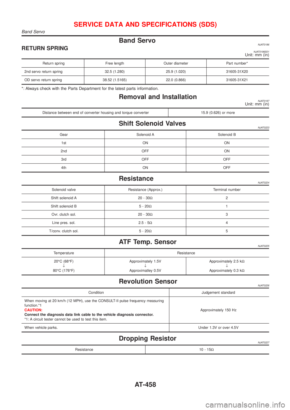
Band ServoNJAT0196RETURN SPRINGNJAT0196S01Unit: mm (in)
Return spring Free length Outer diameter Part number*
2nd servo return spring 32.5 (1.280) 25.9 (1.020) 31605-31X20
OD servo return spring 38.52 (1.5165) 22.0 (0.866) 31605-31X21
*: Always check with the Parts Department for the latest parts information.
Removal and InstallationNJAT0197Unit: mm (in)
Distance between end of converter housing and torque converter 15.9 (0.626) or more
Shift Solenoid ValvesNJAT0223
Gear Solenoid A Solenoid B
1st ON ON
2nd OFF ON
3rd OFF OFF
4th ON OFF
ResistanceNJAT0224
Solenoid valve Resistance (Approx.) Terminal number
Shift solenoid A 20 - 30W2
Shift solenoid B 5 - 20W1
Ovr. clutch sol. 20 - 30W3
Line pres. sol. 2.5 - 5W4
T/conv. clutch sol. 5 - 20W5
ATF Temp. SensorNJAT0225
Temperature Resistance
20ÉC (68ÉF)
¯
80ÉC (176ÉF)Approximately 1.5V
¯
Approximatley 0.5VApproximately 2.5 kW
¯
Approximately 0.3 kW
Revolution SensorNJAT0226
Condition Judgement standard
When moving at 20 km/h (12 MPH), use the CONSULT-II pulse frequency measuring
function.*1
CAUTION:
Connect the diagnosis data link cable to the vehicle diagnosis connector.
*1: A circuit tester cannot be used to test this item.Approximately 150 Hz
When vehicle parks.Under 1.3V or over 4.5V
Dropping ResistorNJAT0227
Resistance 10 - 15W
SERVICE DATA AND SPECIFICATIONS (SDS)
Band Servo
AT-458
Page 2028 of 2493
3 CHECK CIRCUIT CONTINUITY FOR BLOWER MOTOR
1. Turn fan control knob to any position except OFF.
2. Check circuit continuity between blower motor harness terminal No. 2 and body ground.
RHA344FD
Continuity should exist.
If OK, check harness for short.
OK or NG
OK©GO TO 4.
NG©Reconnect blower motor harness connector. GO TO 5.
4 CHECK BLOWER MOTOR
(Refer to Electrical Components Inspection.)
(HA-60)
OK or NG
OK©INSPECTION END
NG©Replace blower motor.
5 CHECK BLOWER MOTOR CIRCUIT BETWEEN BLOWER MOTOR AND RESISTOR
Do approx. 12 volts exist between fan resistor harness terminal No. 1 and body ground?
RHA699HA
YesorNo
Ye s©Disconnect fan switch harness connector. GO TO 7.
No©Disconnect blower motor and resistor harness connectors. GO TO 6.
TROUBLE DIAGNOSES
Blower Motor (Cont'd)
HA-56
Page 2029 of 2493
6 CHECK CIRCUIT CONTINUITY BETWEEN BLOWER MOTOR AND RESISTOR
Check circuit continuity between blower motor harness terminal No. 2 and fan resistor harness terminal No. 1.
RHA700HA
Continuity should exist.
If OK, check harness for short.
OK or NG
OK©Poor contact between the resistor and blower motor connector.
NG©Repair harness or connector.
7 CHECK GROUND CIRCUIT FOR HEATER CONTROL PANEL
Check circuit continuity between fan switch harness terminal No. 9 or 13 and body ground.
NHA506
Continuity should exist.
If OK, check harness for short.
OK or NG
OK©GO TO 8.
NG©Repair harness or connector.
8 CHECK RESISTOR AFTER DISCONNECTING IT
(Refer to Electrical Components Inspection.)
(HA-60)
OK or NG
OK©GO TO 9.
NG©Replace resistor.
9 CHECK RESISTOR HARNESS CONNECTOR
Reconnect resistor harness connector.
OK or NG
1©GO TO 12.
2, 3, 4©GO TO 10.
TROUBLE DIAGNOSES
Blower Motor (Cont'd)
HA-57
Page 2030 of 2493
10 CHECK FAN SWITCH CIRCUIT
Do approx. 12 volts exist between each fan switch harness terminal and body ground?
NHA507
YesorNo
Ye s©GO TO 13.
No©GO TO 11.
11 CHECK CIRCUIT CONTINUITY BETWEEN HEATER CONTROL PANEL AND RESISTOR
Check circuit continuity between heater control panel harness terminals and fan resistor harness terminals.
NHA508
Continuity should exist.
If OK, check harness for short.
OK or NG
OK©GO TO 12.
NG©Repair harness or connector.
TROUBLE DIAGNOSES
Blower Motor (Cont'd)
HA-58
Page 2032 of 2493
NHA386
ELECTRICAL COMPONENTS INSPECTION=NJHA0146Fan SwitchNJHA0146S01Check continuity between terminals at each switch position.
KNOB POSITION Continuity between terminals
OFF No continuity
1 13Ð14Ð18
2 13Ð15Ð18
3 13Ð16Ð18
4 13Ð17Ð18
Blower MotorNJHA0146S02Confirm smooth rotation of the blower motor.
+Ensure that there are no foreign particles inside the intake unit.
RHA706H
Blower ResistorNJHA0146S03Check resistance between terminals.
Terminal No. Resistance
(+) (þ)Models with max
hot doorModels without
max hot door
4
1Approx. 2.4 - 2.8W
3Approx. 0.58 -
0.7WApprox. 1.2 - 1.4W
2Approx. 0.22 -
0.26WApprox. 0.43 -
0.51W
TROUBLE DIAGNOSES
Blower Motor (Cont'd)
HA-60
Page 2068 of 2493
1. Remove the instrument panel assembly. Refer to BT-25,
ªInstrument Panel Assemblyº.
2. Disconnect the blower motor and resistor connector.
3. Remove blower unit.
INSTALLATIONNJHA0196Install in the reverse order of removal.
SERVICE PROCEDURE
Blower Unit (Cont'd)
HA-96