2001 NISSAN ALMERA N16 Parking
[x] Cancel search: ParkingPage 1534 of 2493
SAT058K
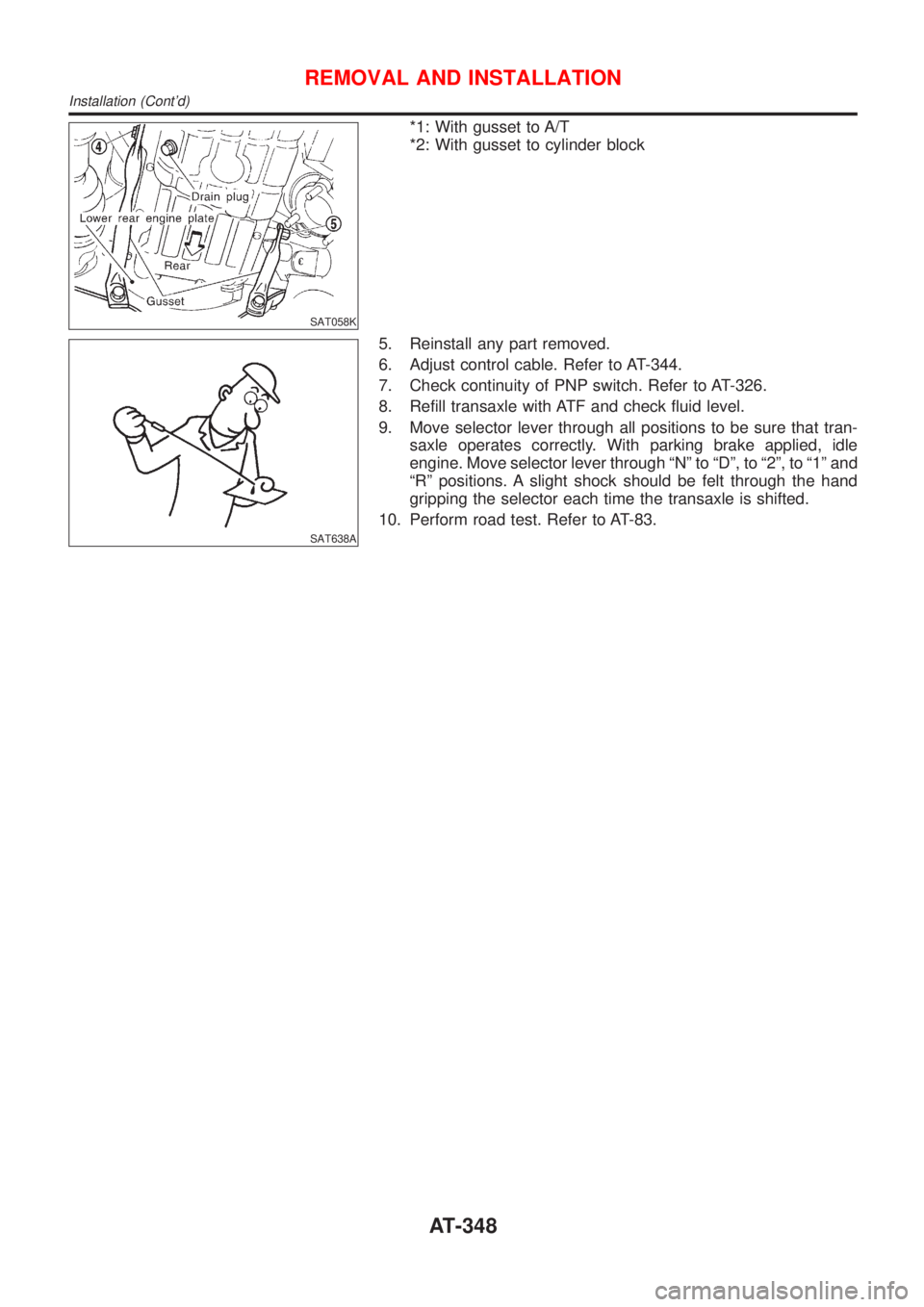
*1: With gusset to A/T
*2: With gusset to cylinder block
SAT638A
5. Reinstall any part removed.
6. Adjust control cable. Refer to AT-344.
7. Check continuity of PNP switch. Refer to AT-326.
8. Refill transaxle with ATF and check fluid level.
9. Move selector lever through all positions to be sure that tran-
saxle operates correctly. With parking brake applied, idle
engine. Move selector lever through ªNº to ªDº, to ª2º, to ª1º and
ªRº positions. A slight shock should be felt through the hand
gripping the selector each time the transaxle is shifted.
10. Perform road test. Refer to AT-83.
REMOVAL AND INSTALLATION
Installation (Cont'd)
AT-348
Page 1552 of 2493
SAT841DA
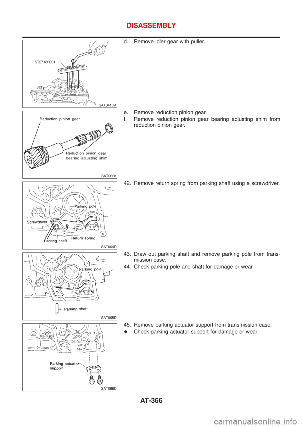
d. Remove idler gear with puller.
SAT062K
e. Remove reduction pinion gear.
f. Remove reduction pinion gear bearing adjusting shim from
reduction pinion gear.
SAT064D
42. Remove return spring from parking shaft using a screwdriver.
SAT065D
43. Draw out parking shaft and remove parking pole from trans-
mission case.
44. Check parking pole and shaft for damage or wear.
SAT066D
45. Remove parking actuator support from transmission case.
+Check parking actuator support for damage or wear.
DISASSEMBLY
AT-366
Page 1554 of 2493
Manual Shaft
COMPONENTSNJAT0121
SAT481J
SAT313G
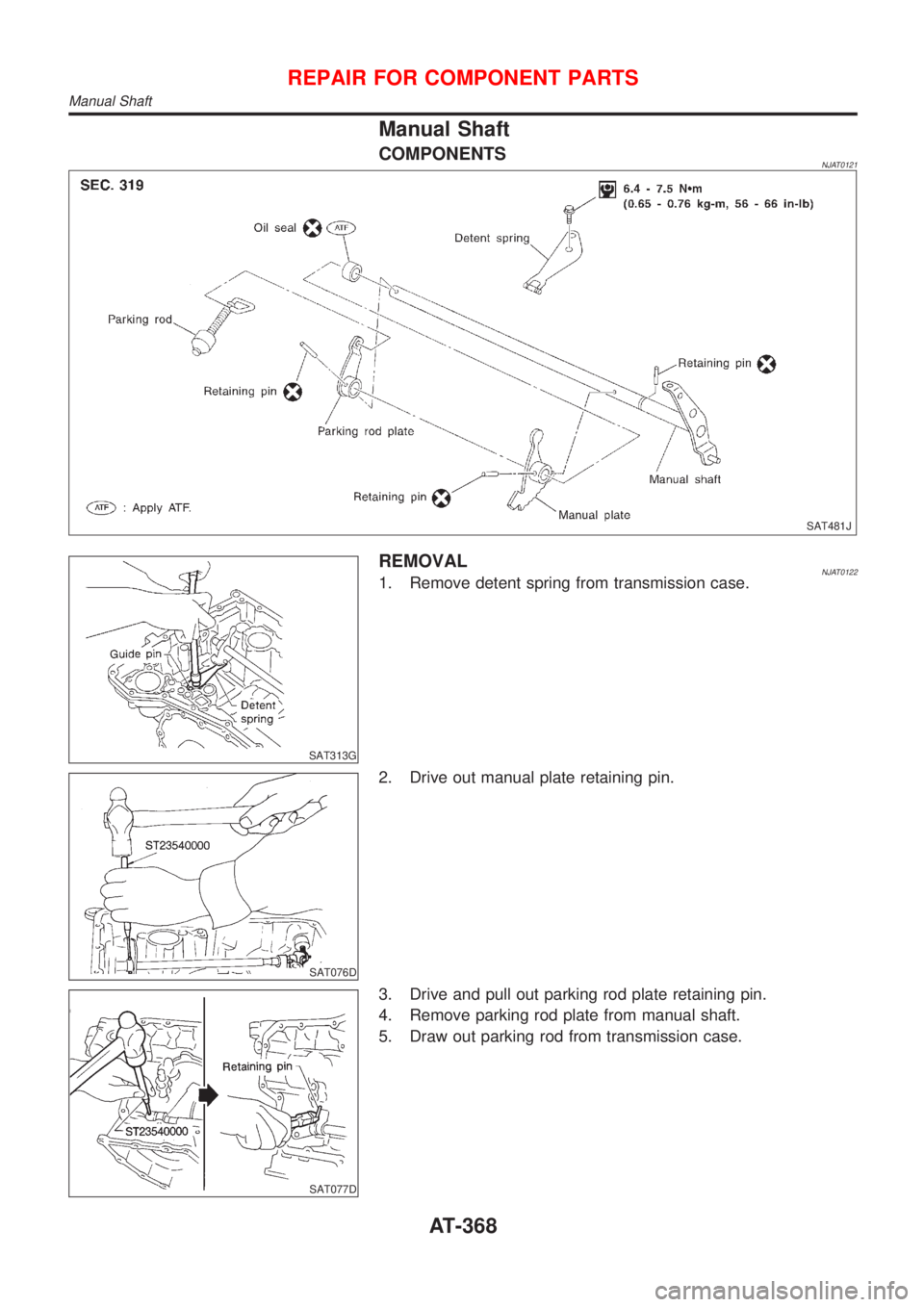
REMOVALNJAT01221. Remove detent spring from transmission case.
SAT076D
2. Drive out manual plate retaining pin.
SAT077D
3. Drive and pull out parking rod plate retaining pin.
4. Remove parking rod plate from manual shaft.
5. Draw out parking rod from transmission case.
REPAIR FOR COMPONENT PARTS
Manual Shaft
AT-368
Page 1556 of 2493
SAT074E
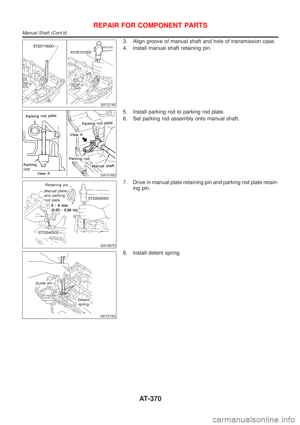
3. Align groove of manual shaft and hole of transmission case.
4. Install manual shaft retaining pin.
SAT078D
5. Install parking rod to parking rod plate.
6. Set parking rod assembly onto manual shaft.
SAT087D
7. Drive in manual plate retaining pin and parking rod plate retain-
ing pin.
SAT313G
8. Install detent spring.
REPAIR FOR COMPONENT PARTS
Manual Shaft (Cont'd)
AT-370
Page 1614 of 2493
SAT311G
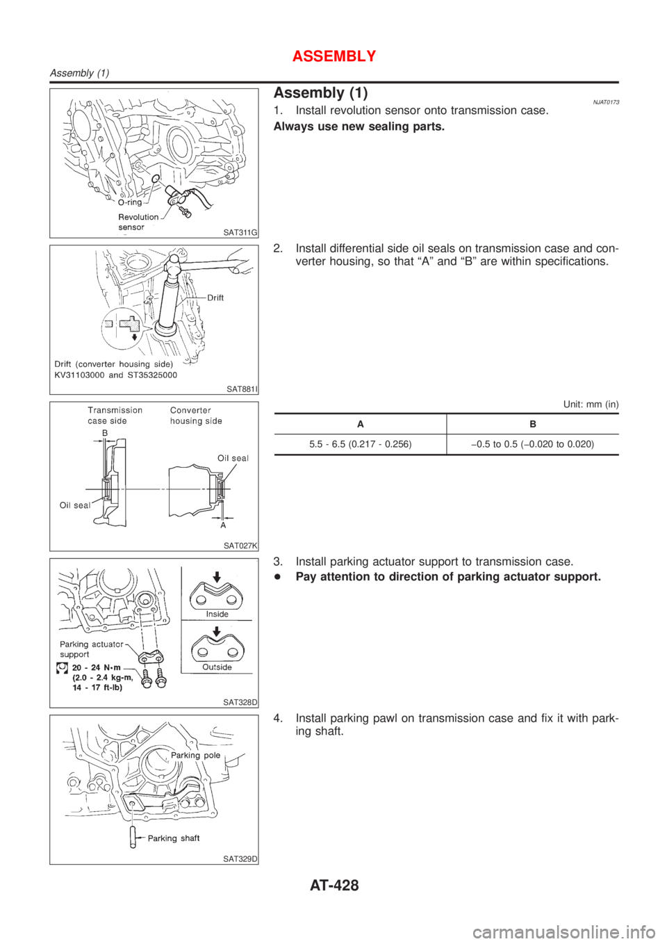
Assembly (1)NJAT01731. Install revolution sensor onto transmission case.
Always use new sealing parts.
SAT881I
2. Install differential side oil seals on transmission case and con-
verter housing, so that ªAº and ªBº are within specifications.
SAT027K
Unit: mm (in)
AB
5.5 - 6.5 (0.217 - 0.256) þ0.5 to 0.5 (þ0.020 to 0.020)
SAT328D
3. Install parking actuator support to transmission case.
+Pay attention to direction of parking actuator support.
SAT329D
4. Install parking pawl on transmission case and fix it with park-
ing shaft.
ASSEMBLY
Assembly (1)
AT-428
Page 1618 of 2493
SAT338DA
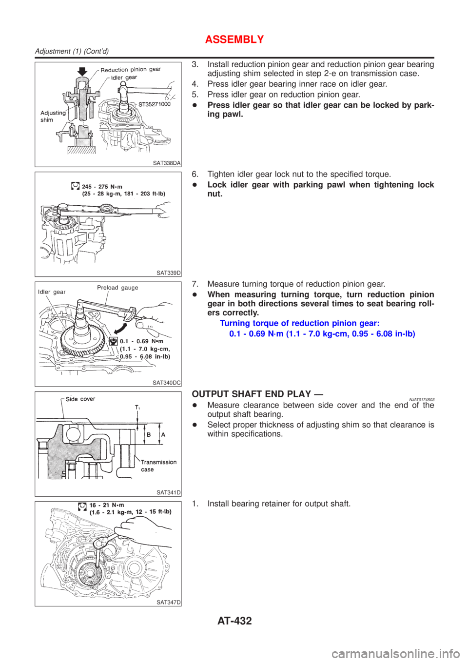
3. Install reduction pinion gear and reduction pinion gear bearing
adjusting shim selected in step 2-e on transmission case.
4. Press idler gear bearing inner race on idler gear.
5. Press idler gear on reduction pinion gear.
+Press idler gear so that idler gear can be locked by park-
ing pawl.
SAT339D
6. Tighten idler gear lock nut to the specified torque.
+Lock idler gear with parking pawl when tightening lock
nut.
SAT340DC
7. Measure turning torque of reduction pinion gear.
+When measuring turning torque, turn reduction pinion
gear in both directions several times to seat bearing roll-
ers correctly.
Turning torque of reduction pinion gear:
0.1 - 0.69 N´m (1.1 - 7.0 kg-cm, 0.95 - 6.08 in-lb)
SAT341D
OUTPUT SHAFT END PLAY ÐNJAT0174S03+Measure clearance between side cover and the end of the
output shaft bearing.
+Select proper thickness of adjusting shim so that clearance is
within specifications.
SAT347D
1. Install bearing retainer for output shaft.
ASSEMBLY
Adjustment (1) (Cont'd)
AT-432
Page 1693 of 2493
SRA695A
SSU038
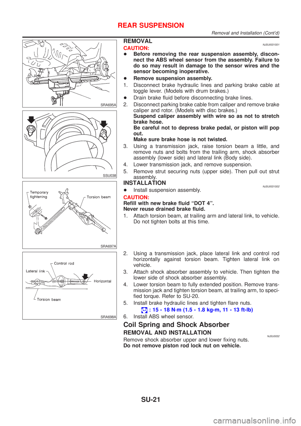
REMOVALNJSU0031S01CAUTION:
+Before removing the rear suspension assembly, discon-
nect the ABS wheel sensor from the assembly. Failure to
do so may result in damage to the sensor wires and the
sensor becoming inoperative.
+Remove suspension assembly.
1. Disconnect brake hydraulic lines and parking brake cable at
toggle lever. (Models with drum brakes.)
+Drain brake fluid before disconnecting brake lines.
2. Disconnect parking brake cable from caliper and remove brake
caliper and rotor. (Models with disc brakes.)
Suspend caliper assembly with wire so as not to stretch
brake hose.
Be careful not to depress brake pedal, or piston will pop
out.
Make sure brake hose is not twisted.
3. Using a transmission jack, raise torsion beam a little, and
remove nuts and bolts from the trailing arm, shock absorber
assembly (lower side) and lateral link (Body side).
4. Lower transmission jack, and remove suspension.
5. Remove strut securing nuts (upper side). Then pull out strut
assembly.
SRA697A
INSTALLATIONNJSU0031S02+Install suspension assembly.
CAUTION:
Refill with new brake fluid ªDOT 4º.
Never reuse drained brake fluid.
1. Attach torsion beam, at trailing arm and lateral link, to vehicle.
Do not tighten bolts at this time.
SRA698A
2. Using a transmission jack, place lateral link and control rod
horizontally against torsion beam. Tighten lateral link on
vehicle.
3. Attach shock absorber assembly to vehicle. Then tighten the
lower side of shock absorber assembly.
4. Lower torsion beam to fully extended position. Remove trans-
mission jack and tighten torsion beam, at trailing arm, to speci-
fied torque. Refer to SU-20.
5. Install brake hydraulic lines and tighten flare nuts.
: 15 - 18 N´m (1.5 - 1.8 kg-m, 11 - 13 ft-lb)
6. Install ABS wheel sensor.
Coil Spring and Shock Absorber
REMOVAL AND INSTALLATIONNJSU0032Remove shock absorber upper and lower fixing nuts.
Do not remove piston rod lock nut on vehicle.
REAR SUSPENSION
Removal and Installation (Cont'd)
SU-21
Page 1700 of 2493

Inspection - Lining .....................................................33
Installation ..................................................................33
REAR DISC BRAKE (CAM & STRUT TYPE)..............35
Component ................................................................35
Pad Replacement ......................................................35
Removal .....................................................................37
Disassembly...............................................................37
Inspection...................................................................38
CALIPER.................................................................38
ROTOR...................................................................39
Assembly ...................................................................39
Installation ..................................................................42
REAR DISC BRAKE (BALL & RAMP TYPE)..............43
Component ................................................................43
Pad Replacement ......................................................43
Removal .....................................................................45
Disassembly...............................................................45
Inspection...................................................................45
CALIPER.................................................................45
ROTOR...................................................................46
Installation ..................................................................46
PARKING BRAKE CONTROL......................................47
Components...............................................................47
Removal and Installation ...........................................47
Inspection...................................................................47
Adjustment .................................................................48
ABS
DESCRIPTION...............................................................49
Purpose......................................................................49
ABS (Anti-Lock Brake System) Operation ................49
ABS Hydraulic Circuit ................................................49
System Components .................................................50
System Description ....................................................50
SENSOR.................................................................50
CONTROL UNIT......................................................50
ABS ACTUATOR AND ELECTRIC UNIT....................50
Component Parts and Harness Connector
Location .....................................................................52
Schematic ..................................................................53
Wiring Diagram - ABS - .............................................54
ON BOARD DIAGNOSTIC SYSTEM
DESCRIPTION...............................................................58
CONSULT-II ...............................................................58
CONSULT-II APPLICATION TO ABS..........................58
ECU (ABS CONTROL UNIT) PART NUMBER
MODE
.....................................................................58
CONSULT-II Inspection Procedure............................58
SELF-DIAGNOSIS PROCEDURE..............................58
SELF-DIAGNOSTIC RESULTS MODE.......................60
DATA MONITOR PROCEDURE................................61
ACTIVE TEST PROCEDURE....................................62
DATA MONITOR MODE...........................................63
ACTIVE TEST MODE...............................................63
TROUBLE DIAGNOSIS - INTRODUCTION..................64
How to Perform Trouble Diagnoses for Quick
and Accurate Repair ..................................................64
INTRODUCTION......................................................64
TROUBLE DIAGNOSIS - BASIC INSPECTION...........65
Preliminary Check......................................................65
Ground Circuit Check ................................................68
ABS ACTUATOR AND ELECTRIC UNIT GROUND.....68
TROUBLE DIAGNOSES FOR SELF-DIAGNOSTIC
ITEMS.............................................................................69
Wheel Sensor or Rotor ..............................................69
DIAGNOSTIC PROCEDURE.....................................69
ABS Actuator Solenoid Valve or Solenoid Valve
Relay ..........................................................................72
DIAGNOSTIC PROCEDURE.....................................72
Motor Relay or Motor.................................................75
DIAGNOSTIC PROCEDURE.....................................75
Low Voltage ...............................................................77
DIAGNOSTIC PROCEDURE.....................................77
Control Unit ................................................................79
DIAGNOSTIC PROCEDURE.....................................79
TROUBLE DIAGNOSES FOR SYMPTOMS.................80
1. ABS Works Frequently ..........................................80
2. Unexpected Pedal Action ......................................80
3. Long Stopping Distance ........................................81
4. ABS Does Not Work ..............................................82
5. Pedal Vibration and Noise.....................................83
6. ABS Warning Lamp Does Not Come On
When Ignition Switch Is Turned On...........................84
7. ABS Warning Lamp Stays On When Ignition
Switch Is Turned On ..................................................86
REMOVAL AND INSTALLATION.................................88
Wheel Sensors ..........................................................88
ABS Actuator and Electric Unit..................................89
REMOVAL...............................................................89
INSTALLATION........................................................89
Sensor Rotor..............................................................90
REMOVAL...............................................................90
INSTALLATION........................................................90
SERVICE DATA AND SPECIFICATIONS (SDS).........91
General Specifications ...............................................91
Disc Brake .................................................................91
Drum Brake................................................................91
Brake Pedal ...............................................................92
Parking Brake ............................................................92
CONTENTS(Cont'd)
BR-2