2001 NISSAN ALMERA N16 Parking
[x] Cancel search: ParkingPage 1745 of 2493
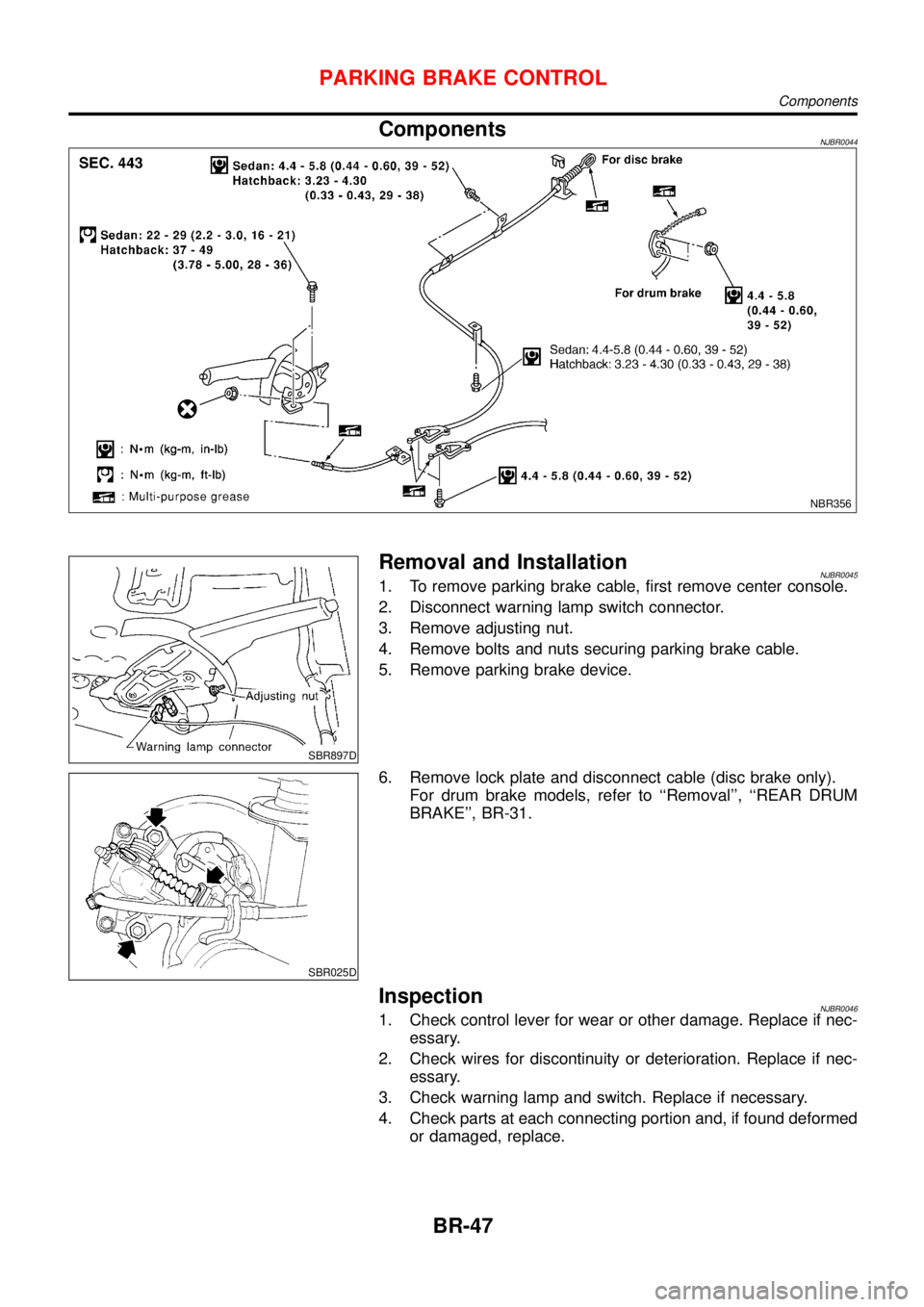
ComponentsNJBR0044
NBR356
SBR897D
Removal and InstallationNJBR00451. To remove parking brake cable, first remove center console.
2. Disconnect warning lamp switch connector.
3. Remove adjusting nut.
4. Remove bolts and nuts securing parking brake cable.
5. Remove parking brake device.
SBR025D
6. Remove lock plate and disconnect cable (disc brake only).
For drum brake models, refer to ‘‘Removal’’, ‘‘REAR DRUM
BRAKE’’, BR-31.
InspectionNJBR00461. Check control lever for wear or other damage. Replace if nec-
essary.
2. Check wires for discontinuity or deterioration. Replace if nec-
essary.
3. Check warning lamp and switch. Replace if necessary.
4. Check parts at each connecting portion and, if found deformed
or damaged, replace.
PARKING BRAKE CONTROL
Components
BR-47
Page 1746 of 2493
SBR768E
AdjustmentNJBR0047Before or after adjustment, pay attention to the following points.
+For rear disc brake be sure that toggle lever returns to stop-
per when parking brake lever is released.
+There is no drag when parking brake lever is released.
+Vehicle is unladen.
1. Adjust clearance between shoe and drum or pad and rotor as
follows:
a. Release parking brake lever and loosen adjusting nut.
b. Depress brake pedal fully at least 10 times with engine run-
ning.
SBR756E
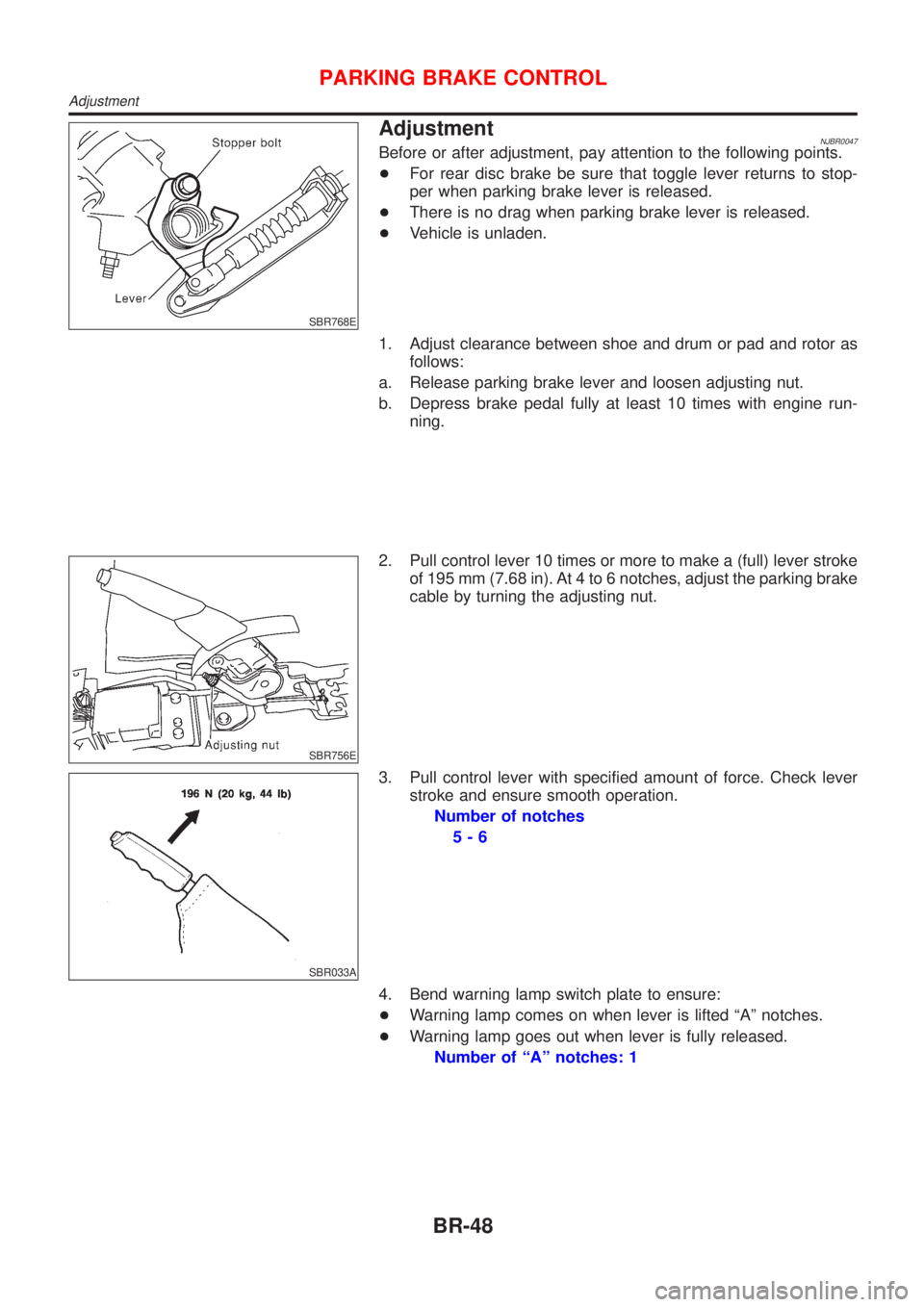
2. Pull control lever 10 times or more to make a (full) lever stroke
of 195 mm (7.68 in). At 4 to 6 notches, adjust the parking brake
cable by turning the adjusting nut.
SBR033A
3. Pull control lever with specified amount of force. Check lever
stroke and ensure smooth operation.
Number of notches
5-6
4. Bend warning lamp switch plate to ensure:
+Warning lamp comes on when lever is lifted ªAº notches.
+Warning lamp goes out when lever is fully released.
Number of ªAº notches: 1
PARKING BRAKE CONTROL
Adjustment
BR-48
Page 1790 of 2493
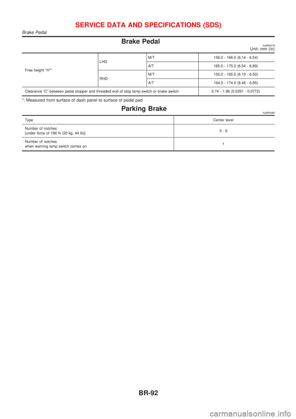
Brake PedalNJBR0079Unit: mm (in)
Free height ªHº*LHDM/T 156.0 - 166.0 (6.14 - 6.54)
A/T 165.0 - 175.0 (6.54 - 6.89)
RHDM/T 155.0 - 165.0 (6.10 - 6.50)
A/T 164.0 - 174.0 (6.46 - 6.85)
Clearance ªCº between pedal stopper and threaded end of stop lamp switch or brake switch 0.74 - 1.96 (0.0291 - 0.0772)
*: Measured from surface of dash panel to surface of pedal pad
Parking BrakeNJBR0080
TypeCenter lever
Number of notches
[under force of 196 N (20 kg, 44 lb)]5-6
Number of notches
when warning lamp switch comes on1
SERVICE DATA AND SPECIFICATIONS (SDS)
Brake Pedal
BR-92
Page 1798 of 2493
Bleeding Hydraulic SystemNJST00141. Raise front end of vehicle until wheels are clear of the ground.
2. Add fluid into oil tank to specified level. Then quickly turn steer-
ing wheel fully to right and left and lightly touch steering stop-
pers.
Repeat steering wheel operation until fluid level no longer
decreases.
3. Start engine.
Repeat step 2. above.
+Incomplete air bleeding will cause the following to occur. When
this happens, bleed air again.
a) Air bubbles in reservoir tank
b) Clicking noise in oil pump
c) Excessive buzzing in oil pump
Fluid noise may occur in the valve or oil pump. This is common
when the vehicle is stationary or while turning the steering wheel
slowly. This does not affect the performance or durability of the
system.
SST491B
SST090B
Checking Steering Wheel Turning ForceNJST00151. Park vehicle on a level, dry surface and set parking brake.
2. Start engine.
3. Bring power steering fluid up to adequate operating tempera-
ture. [Make sure temperature of fluid is approximately 60 to
80ÉC (140 to 176ÉF).]
Tires need to be inflated to normal pressure.
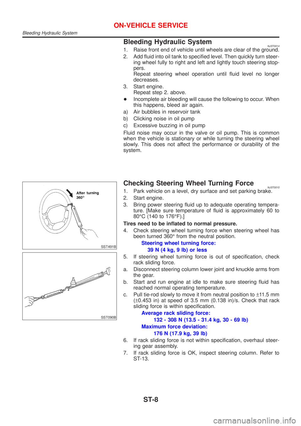
4. Check steering wheel turning force when steering wheel has
been turned 360É from the neutral position.
Steering wheel turning force:
39 N (4 kg, 9 lb) or less
5. If steering wheel turning force is out of specification, check
rack sliding force.
a. Disconnect steering column lower joint and knuckle arms from
the gear.
b. Start and run engine at idle to make sure steering fluid has
reached normal operating temperature.
c. Pull tie-rod slowly to move it from neutral position to±11.5 mm
(±0.453 in) at speed of 3.5 mm (0.138 in)/s. Check that rack
sliding force is within specification.
Average rack sliding force:
132 - 308 N (13.5 - 31.4 kg, 30 - 69 lb)
Maximum force deviation:
176 N (17.9 kg, 39 lb)
6. If rack sliding force is not within specification, overhaul steer-
ing gear assembly.
7. If rack sliding force is OK, inspect steering column. Refer to
ST-13.
ON-VEHICLE SERVICE
Bleeding Hydraulic System
ST-8
Page 2113 of 2493
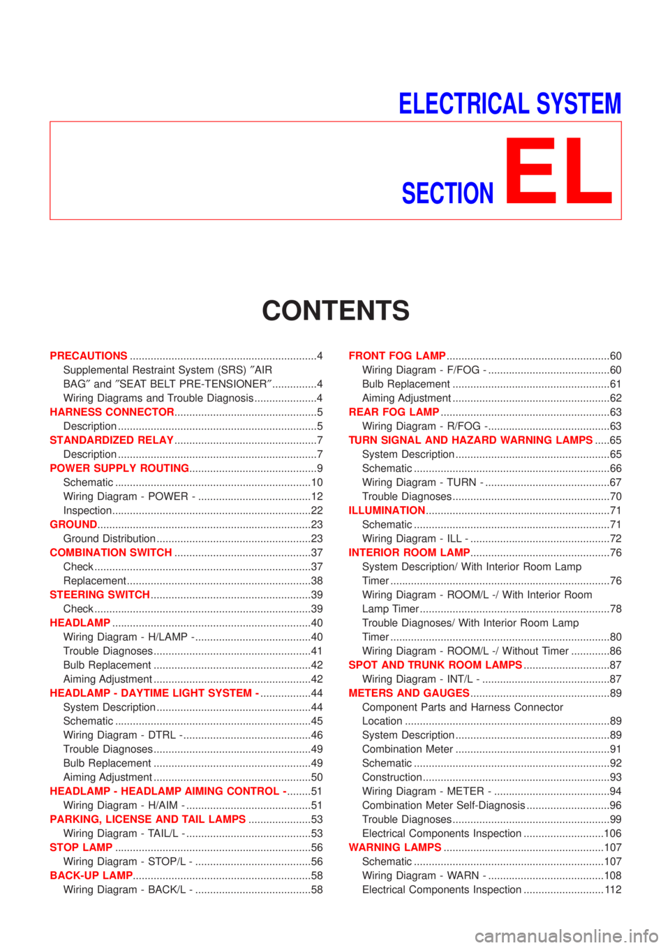
ELECTRICAL SYSTEM
SECTION
EL
CONTENTS
PRECAUTIONS...............................................................4
Supplemental Restraint System (SRS)²AIR
BAG²and²SEAT BELT PRE-TENSIONER²...............4
Wiring Diagrams and Trouble Diagnosis .....................4
HARNESS CONNECTOR................................................5
Description ...................................................................5
STANDARDIZED RELAY................................................7
Description ...................................................................7
POWER SUPPLY ROUTING...........................................9
Schematic ..................................................................10
Wiring Diagram - POWER - ......................................12
Inspection...................................................................22
GROUND........................................................................23
Ground Distribution ....................................................23
COMBINATION SWITCH..............................................37
Check .........................................................................37
Replacement ..............................................................38
STEERING SWITCH......................................................39
Check .........................................................................39
HEADLAMP...................................................................40
Wiring Diagram - H/LAMP -.......................................40
Trouble Diagnoses.....................................................41
Bulb Replacement .....................................................42
Aiming Adjustment .....................................................42
HEADLAMP - DAYTIME LIGHT SYSTEM -.................44
System Description ....................................................44
Schematic ..................................................................45
Wiring Diagram - DTRL - ...........................................46
Trouble Diagnoses.....................................................49
Bulb Replacement .....................................................49
Aiming Adjustment .....................................................50
HEADLAMP - HEADLAMP AIMING CONTROL -........51
Wiring Diagram - H/AIM - ..........................................51
PARKING, LICENSE AND TAIL LAMPS.....................53
Wiring Diagram - TAIL/L - ..........................................53
STOP LAMP..................................................................56
Wiring Diagram - STOP/L - .......................................56
BACK-UP LAMP............................................................58
Wiring Diagram - BACK/L - .......................................58FRONT FOG LAMP.......................................................60
Wiring Diagram - F/FOG - .........................................60
Bulb Replacement .....................................................61
Aiming Adjustment .....................................................62
REAR FOG LAMP.........................................................63
Wiring Diagram - R/FOG -.........................................63
TURN SIGNAL AND HAZARD WARNING LAMPS.....65
System Description ....................................................65
Schematic ..................................................................66
Wiring Diagram - TURN - ..........................................67
Trouble Diagnoses.....................................................70
ILLUMINATION..............................................................71
Schematic ..................................................................71
Wiring Diagram - ILL - ...............................................72
INTERIOR ROOM LAMP...............................................76
System Description/ With Interior Room Lamp
Timer ..........................................................................76
Wiring Diagram - ROOM/L -/ With Interior Room
Lamp Timer ................................................................78
Trouble Diagnoses/ With Interior Room Lamp
Timer ..........................................................................80
Wiring Diagram - ROOM/L -/ Without Timer .............86
SPOT AND TRUNK ROOM LAMPS.............................87
Wiring Diagram - INT/L - ...........................................87
METERS AND GAUGES...............................................89
Component Parts and Harness Connector
Location .....................................................................89
System Description ....................................................89
Combination Meter ....................................................91
Schematic ..................................................................92
Construction ...............................................................93
Wiring Diagram - METER - .......................................94
Combination Meter Self-Diagnosis ............................96
Trouble Diagnoses.....................................................99
Electrical Components Inspection ...........................106
WARNING LAMPS......................................................107
Schematic ................................................................107
Wiring Diagram - WARN - .......................................108
Electrical Components Inspection ........................... 112
Page 2156 of 2493
System DescriptionNJEL0351The headlamp system on vehicles for North Europe contains a daytime light unit. The unit activates the fol-
lowing whenever the engine is running with the lighting switch in the OFF position:
+Low beam headlamps
+Parking, license, tail and illumination lamps
Power is supplied at all times
+through 10A fuse (No. 38, located in the fusible link and fuse box)
+to daytime light unit terminal 1 and
+to lighting switch terminal 11.
Power is also supplied at all times
+through 15A fuse (No. 39, located in the fusible link and fuse box)
+to daytime light unit terminal 3 and
+to lighting switch terminal 5.
Power is also supplied at all times
+through 15A fuse (No. 40, located in the fusible link and fuse box)
+to daytime light unit terminal 2 and
+to lighting switch terminal 8.
With the ignition switch in the ON or START position, power is supplied
+through 10A fuse [No. 20, located in the fuse block (J/B)]
+to daytime light unit terminal 7.
With the ignition switch in the START position, power is supplied
+through 10A fuse [No. 21, located in the fuse block (J/B)]
+to daytime light unit terminal 6.
Ground is supplied to daytime light unit terminal 9 through body grounds E30 and E73.
HEADLAMP OPERATION (DAYTIME LIGHT CANCEL OPERATION)NJEL0351S01When the lighting switch is turned to the 1st or 2nd position, power is supplied
+through lighting switch terminal 12,
+to daytime light unit terminal 11.
Then daytime light will be canceled. And the lighting system operation will be the same as no daytime light
system.
DAYTIME LIGHT OPERATIONNJEL0351S02With the engine running and the lighting switch in the OFF position, power is supplied
+from alternator terminal 3
+to daytime light unit terminal 8,
+through daytime light unit terminal 5
+to terminal 3 of headlamp LH,
+through daytime light unit terminal 4
+to terminal 3 of headlamp RH and
+through daytime light unit terminal 10
+to tail lamp and illumination.
Ground is supplied to terminal 2 of each headlamp through body grounds E30 and E73.
HEADLAMP Ð DAYTIME LIGHT SYSTEM Ð
System Description
EL-44
Page 2165 of 2493
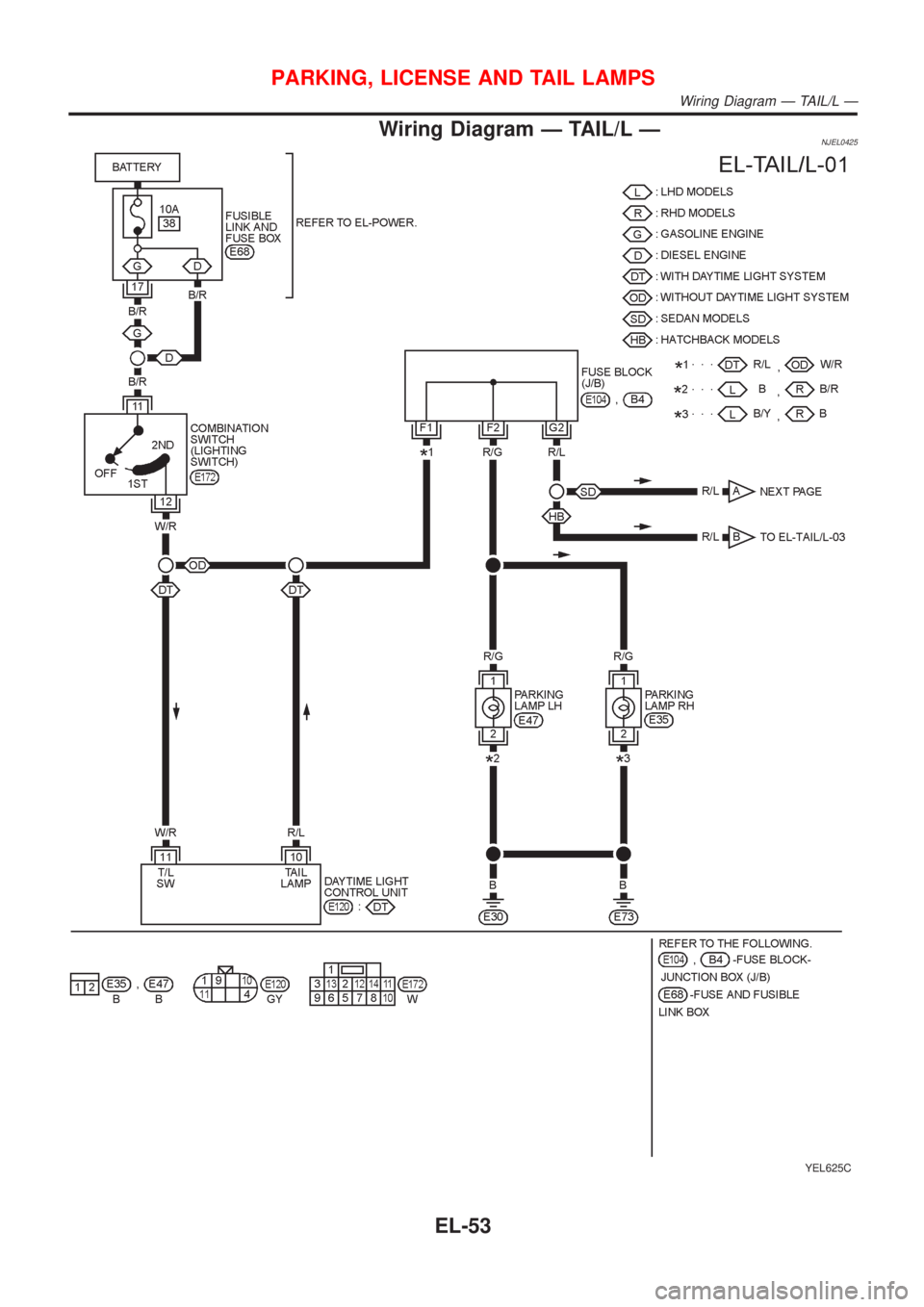
Wiring Diagram Ð TAIL/L ÐNJEL0425
YEL625C
PARKING, LICENSE AND TAIL LAMPS
Wiring Diagram Ð TAIL/L Ð
EL-53
Page 2166 of 2493
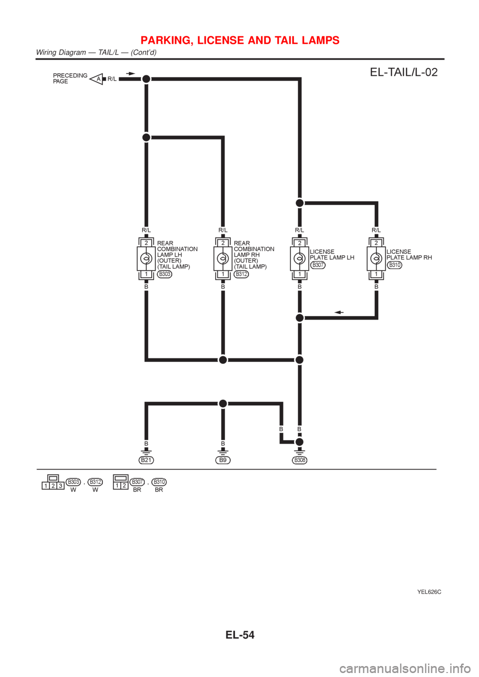
YEL626C
PARKING, LICENSE AND TAIL LAMPS
Wiring Diagram Ð TAIL/L Ð (Cont'd)
EL-54