Page 1523 of 2493
Diagnostic ProcedureNJAT0105SYMPTOM 1:
+Selector lever cannot be moved from ªPº position with key
in ON position and brake pedal applied.
+Selector lever can be moved from ªPº position with key in
ON position and brake pedal released.
+Selector lever can be moved from ªPº position when key
is removed from key cylinder.
SYMPTOM 2:
Ignition key cannot be removed when selector lever is set to
ªPº position. It can be removed when selector lever is set to
any position except ªPº.
1 CHECK KEY INTERLOCK CABLE
Check key interlock cable for damage.
OK or NG
OK©GO TO 2.
NG©Repair key interlock cable. Refer to AT-341.
2 CHECK SELECTOR LEVER POSITION
Check selector lever position for damage.
OK or NG
OK©GO TO 3.
NG©Check selector lever. Refer to ªON-VEHICLE SERVICE Ð PNP Switch and Control
Cable Adjustmentº, AT-344.
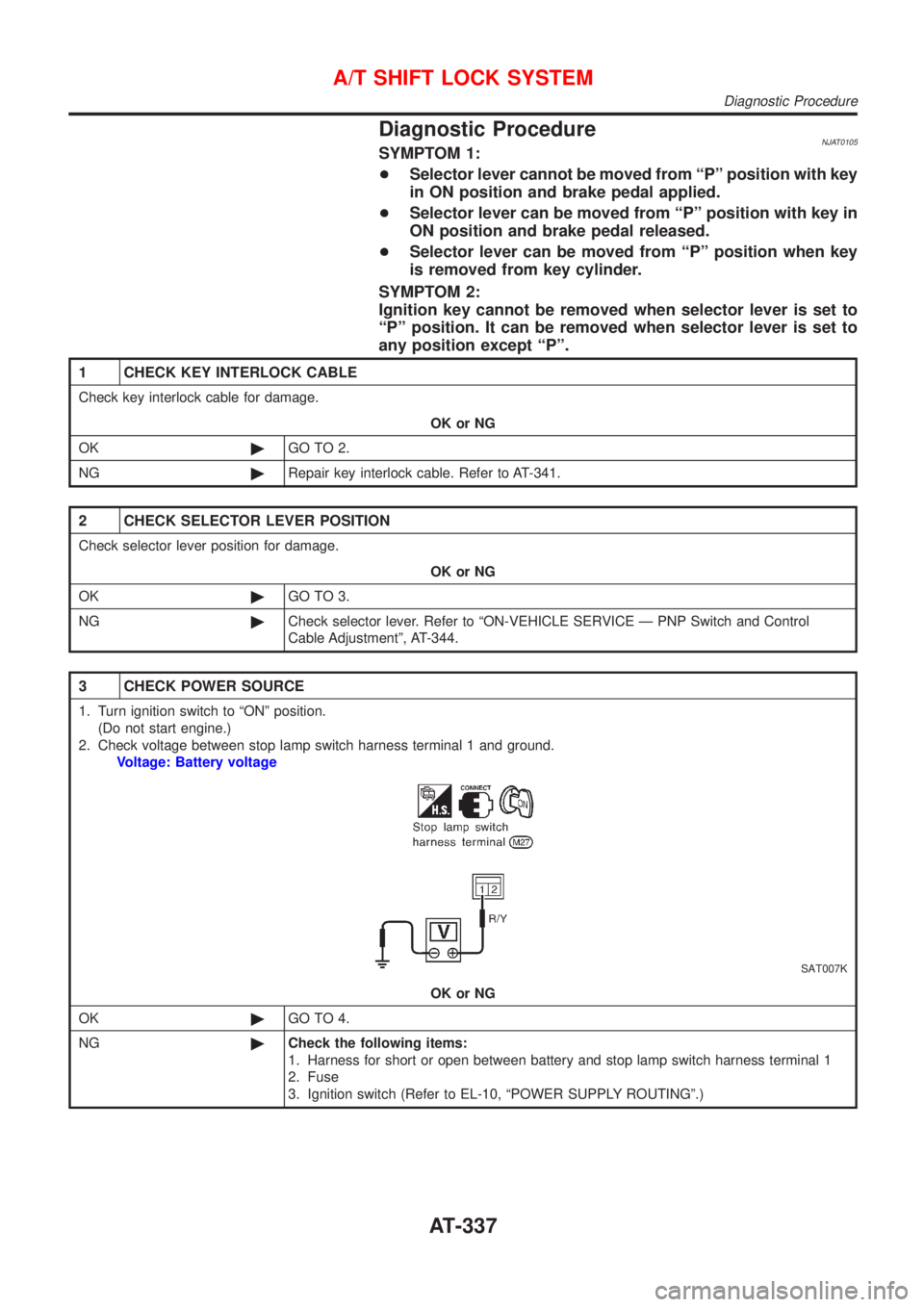
3 CHECK POWER SOURCE
1. Turn ignition switch to ªONº position.
(Do not start engine.)
2. Check voltage between stop lamp switch harness terminal 1 and ground.
Voltage: Battery voltage
SAT007K
OK or NG
OK©GO TO 4.
NG©Check the following items:
1. Harness for short or open between battery and stop lamp switch harness terminal 1
2. Fuse
3. Ignition switch (Refer to EL-10, ªPOWER SUPPLY ROUTINGº.)
A/T SHIFT LOCK SYSTEM
Diagnostic Procedure
AT-337
Page 1529 of 2493
SAT992C
Control Valve Assembly and AccumulatorsNJAT0110REMOVALNJAT0110S011. Drain ATF from transaxle.
2. Remove oil pan and gasket.
SAT064K
3. Disconnect A/T solenoid valve harness connector.
AAT265A
4. Remove stopper ring from A/T solenoid harness terminal body.
5. Remove A/T solenoid harness by pushing terminal body into
transmission case.
AAT260A
6. Remove control valve assembly by removing fixing bolts.
Bolt length, number and location:
Bolt symbol A B C
Bolt length ª!º
40.0 mm
(1.575 in)33.0 mm
(1.299 in)43.5 mm
(1.713 in)
Number of bolts 5 6 2
+Be careful not to drop manual valve and servo release
accumulator return springs.
7. Disassemble and inspect control valve assembly if necessary.
Refer to AT-354.
ON-VEHICLE SERVICE
Control Valve Assembly and Accumulators
AT-343
Page 1530 of 2493
SAT935J
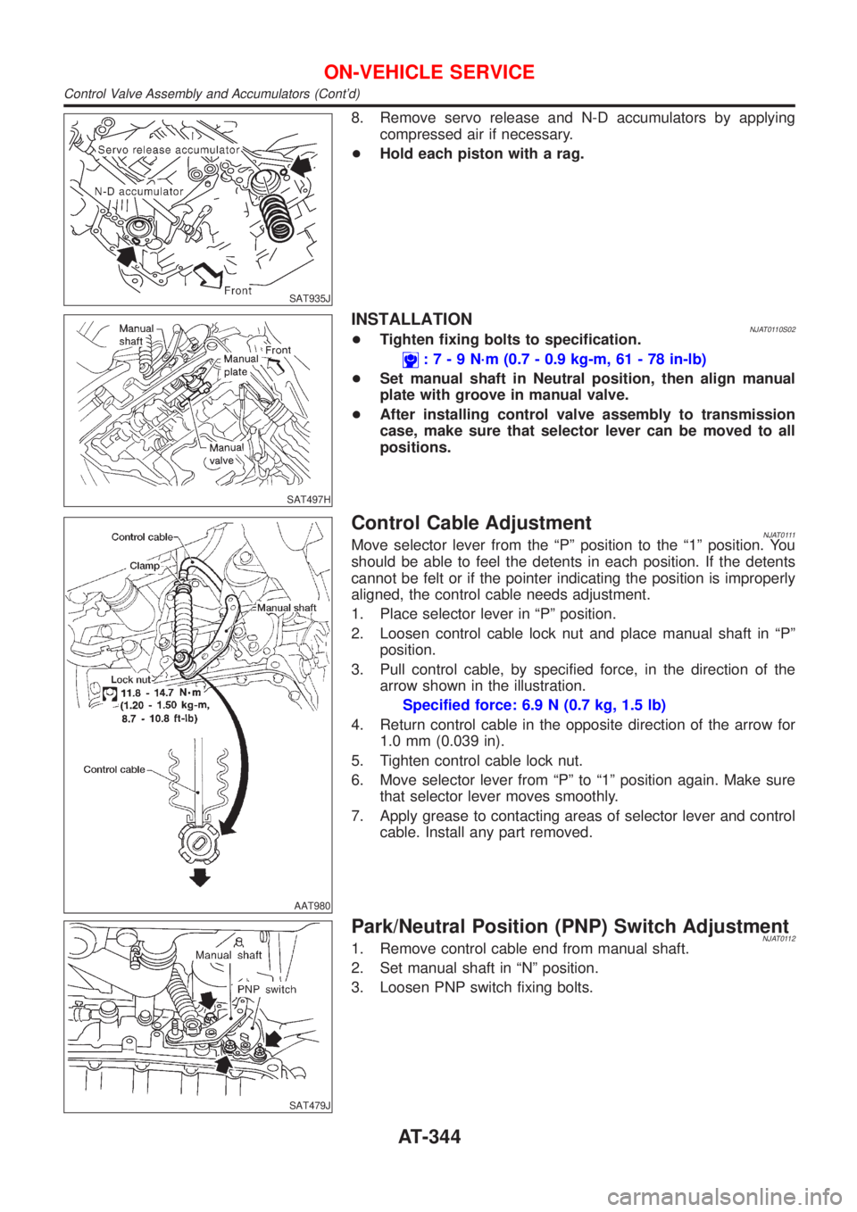
8. Remove servo release and N-D accumulators by applying
compressed air if necessary.
+Hold each piston with a rag.
SAT497H
INSTALLATIONNJAT0110S02+Tighten fixing bolts to specification.
:7-9N´m(0.7 - 0.9 kg-m, 61 - 78 in-lb)
+Set manual shaft in Neutral position, then align manual
plate with groove in manual valve.
+After installing control valve assembly to transmission
case, make sure that selector lever can be moved to all
positions.
AAT980
Control Cable AdjustmentNJAT0111Move selector lever from the ªPº position to the ª1º position. You
should be able to feel the detents in each position. If the detents
cannot be felt or if the pointer indicating the position is improperly
aligned, the control cable needs adjustment.
1. Place selector lever in ªPº position.
2. Loosen control cable lock nut and place manual shaft in ªPº
position.
3. Pull control cable, by specified force, in the direction of the
arrow shown in the illustration.
Specified force: 6.9 N (0.7 kg, 1.5 lb)
4. Return control cable in the opposite direction of the arrow for
1.0 mm (0.039 in).
5. Tighten control cable lock nut.
6. Move selector lever from ªPº to ª1º position again. Make sure
that selector lever moves smoothly.
7. Apply grease to contacting areas of selector lever and control
cable. Install any part removed.
SAT479J
Park/Neutral Position (PNP) Switch AdjustmentNJAT01121. Remove control cable end from manual shaft.
2. Set manual shaft in ªNº position.
3. Loosen PNP switch fixing bolts.
ON-VEHICLE SERVICE
Control Valve Assembly and Accumulators (Cont'd)
AT-344
Page 1531 of 2493
SAT480J
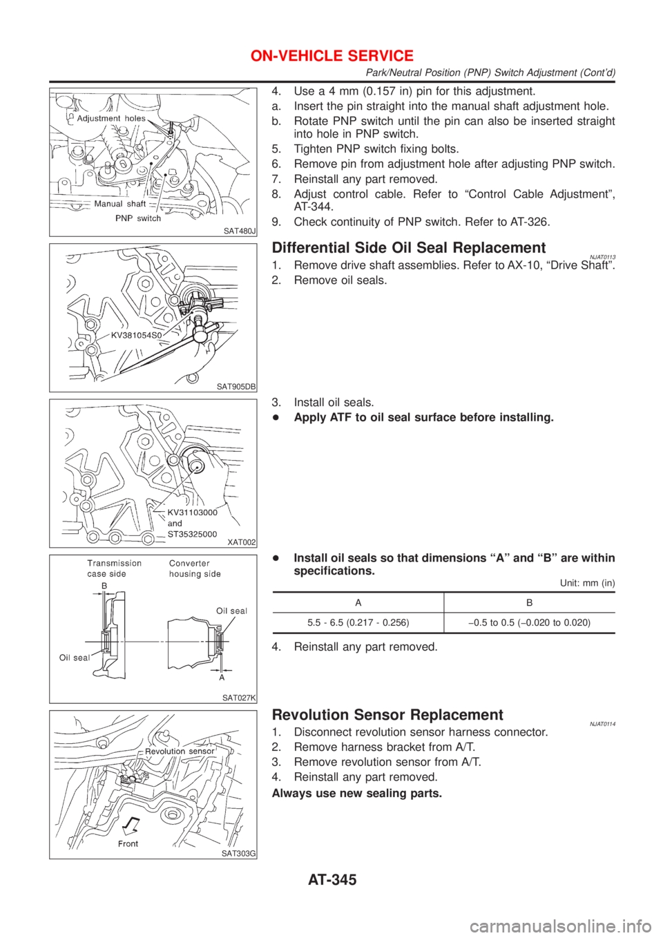
4. Usea4mm(0.157 in) pin for this adjustment.
a. Insert the pin straight into the manual shaft adjustment hole.
b. Rotate PNP switch until the pin can also be inserted straight
into hole in PNP switch.
5. Tighten PNP switch fixing bolts.
6. Remove pin from adjustment hole after adjusting PNP switch.
7. Reinstall any part removed.
8. Adjust control cable. Refer to ªControl Cable Adjustmentº,
AT-344.
9. Check continuity of PNP switch. Refer to AT-326.
SAT905DB
Differential Side Oil Seal ReplacementNJAT01131. Remove drive shaft assemblies. Refer to AX-10, ªDrive Shaftº.
2. Remove oil seals.
XAT002
3. Install oil seals.
+Apply ATF to oil seal surface before installing.
SAT027K
+Install oil seals so that dimensions ªAº and ªBº are within
specifications.
Unit: mm (in)
AB
5.5 - 6.5 (0.217 - 0.256) þ0.5 to 0.5 (þ0.020 to 0.020)
4. Reinstall any part removed.
SAT303G
Revolution Sensor ReplacementNJAT01141. Disconnect revolution sensor harness connector.
2. Remove harness bracket from A/T.
3. Remove revolution sensor from A/T.
4. Reinstall any part removed.
Always use new sealing parts.
ON-VEHICLE SERVICE
Park/Neutral Position (PNP) Switch Adjustment (Cont'd)
AT-345
Page 1635 of 2493
General SpecificationsNJAT0179
Applied modelRE4F03B
QG18DE
Automatic transaxle assembly 3AX18
Transaxle gear
ratio1st 2.861
2nd 1.562
3rd 1.000
4th 0.697
Reverse 2.310
Final drive 4.072
Recommended fluid Genuine Nissan ATF or equivalent*1
Fluid capacity!(Imp qt) 7.0 (6-1/8)
*1: Refer to MA-20, ªFluids and Lubricantsº.
Shift ScheduleNJAT0180VEHICLE SPEED WHEN SHIFTING GEARSNJAT0180S01
Throttle positionVehicle speed km/h (MPH)
D
1®D2D2®D3D3®D4D4®D3D3®D2D2®D112®11
Full throttle51-59
(32 - 37)97 - 105
(60 - 65)154 - 162
(96 - 101)150 - 158
(93 - 98)87-95
(54 - 59)41-49
(25 - 30)51-59
(32 - 37)
Half throttle28-36
(17 - 22)52-60
(32 - 37)117 - 125
(73 - 78)66-74
(41 - 46)33-41
(21 - 25)5-13
(3-8)51-59
(32 - 37)
SERVICE DATA AND SPECIFICATIONS (SDS)
General Specifications
AT-449
Page 1636 of 2493
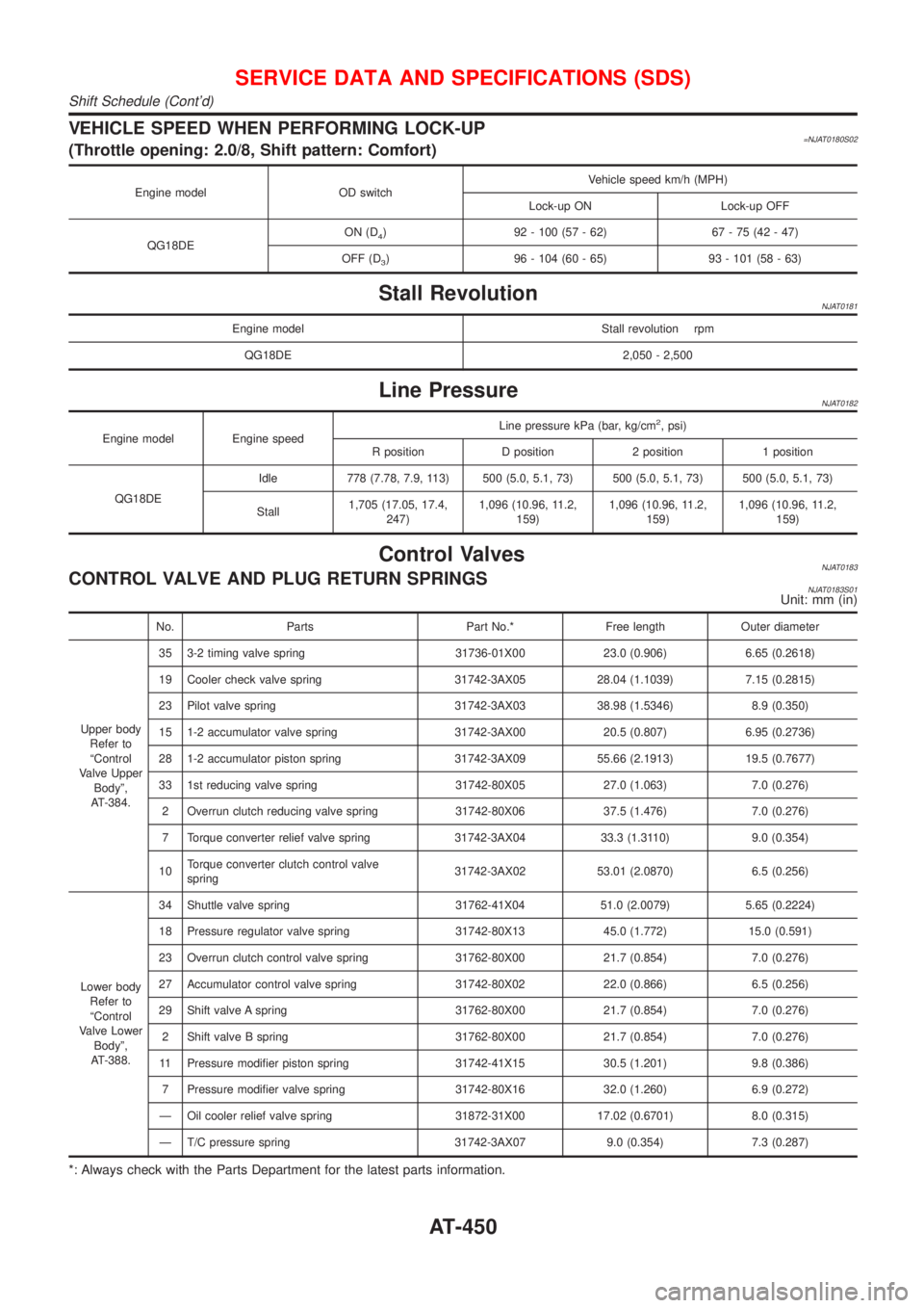
VEHICLE SPEED WHEN PERFORMING LOCK-UP=NJAT0180S02(Throttle opening: 2.0/8, Shift pattern: Comfort)
Engine model OD switchVehicle speed km/h (MPH)
Lock-up ON Lock-up OFF
QG18DEON (D
4) 92 - 100 (57 - 62) 67 - 75 (42 - 47)
OFF (D
3) 96 - 104 (60 - 65) 93 - 101 (58 - 63)
Stall RevolutionNJAT0181
Engine model Stall revolution rpm
QG18DE 2,050 - 2,500
Line PressureNJAT0182
Engine model Engine speedLine pressure kPa (bar, kg/cm
2, psi)
R position D position 2 position 1 position
QG18DEIdle 778 (7.78, 7.9, 113) 500 (5.0, 5.1, 73) 500 (5.0, 5.1, 73) 500 (5.0, 5.1, 73)
Stall1,705 (17.05, 17.4,
247)1,096 (10.96, 11.2,
159)1,096 (10.96, 11.2,
159)1,096 (10.96, 11.2,
159)
Control ValvesNJAT0183CONTROL VALVE AND PLUG RETURN SPRINGSNJAT0183S01Unit: mm (in)
No. Parts Part No.* Free length Outer diameter
Upper body
Refer to
ªControl
Valve Upper
Bodyº,
AT-384.35 3-2 timing valve spring 31736-01X00 23.0 (0.906) 6.65 (0.2618)
19 Cooler check valve spring 31742-3AX05 28.04 (1.1039) 7.15 (0.2815)
23 Pilot valve spring 31742-3AX03 38.98 (1.5346) 8.9 (0.350)
15 1-2 accumulator valve spring 31742-3AX00 20.5 (0.807) 6.95 (0.2736)
28 1-2 accumulator piston spring 31742-3AX09 55.66 (2.1913) 19.5 (0.7677)
33 1st reducing valve spring 31742-80X05 27.0 (1.063) 7.0 (0.276)
2 Overrun clutch reducing valve spring 31742-80X06 37.5 (1.476) 7.0 (0.276)
7 Torque converter relief valve spring 31742-3AX04 33.3 (1.3110) 9.0 (0.354)
10Torque converter clutch control valve
spring31742-3AX02 53.01 (2.0870) 6.5 (0.256)
Lower body
Refer to
ªControl
Valve Lower
Bodyº,
AT-388.34 Shuttle valve spring 31762-41X04 51.0 (2.0079) 5.65 (0.2224)
18 Pressure regulator valve spring 31742-80X13 45.0 (1.772) 15.0 (0.591)
23 Overrun clutch control valve spring 31762-80X00 21.7 (0.854) 7.0 (0.276)
27 Accumulator control valve spring 31742-80X02 22.0 (0.866) 6.5 (0.256)
29 Shift valve A spring 31762-80X00 21.7 (0.854) 7.0 (0.276)
2 Shift valve B spring 31762-80X00 21.7 (0.854) 7.0 (0.276)
11 Pressure modifier piston spring 31742-41X15 30.5 (1.201) 9.8 (0.386)
7 Pressure modifier valve spring 31742-80X16 32.0 (1.260) 6.9 (0.272)
Ð Oil cooler relief valve spring 31872-31X00 17.02 (0.6701) 8.0 (0.315)
Ð T/C pressure spring 31742-3AX07 9.0 (0.354) 7.3 (0.287)
*: Always check with the Parts Department for the latest parts information.
SERVICE DATA AND SPECIFICATIONS (SDS)
Shift Schedule (Cont'd)
AT-450
Page 1637 of 2493

Clutch and BrakesNJAT0184REVERSE CLUTCHNJAT0184S01
Number of drive plates2
Number of driven plates2
Drive plate thickness mm (in)Standard 2.0 (0.079)
Allowable limit 1.8 (0.071)
Clearance mm (in)Standard 0.5 - 0.8 (0.020 - 0.031)
Allowable limit 1.2 (0.047)
Thickness of retaining platesThickness mm (in) Part number*
4.4 (0.173)
4.6 (0.181)
4.8 (0.189)
5.0 (0.197)
5.2 (0.205)31537-31X00
31537-31X01
31537-31X02
31537-31X03
31537-31X04
*: Always check with the Parts Department for the latest parts information.
HIGH CLUTCHNJAT0184S02
Number of drive plates3
Number of driven plates5
Drive plate thickness mm (in)Standard 1.6 (0.063)
Allowable limit 1.4 (0.055)
Clearance mm (in)Standard 1.4 - 1.8 (0.055 - 0.071)
Allowable limit 2.4 (0.094)
Thickness of retaining plateThickness mm (in) Part number*
3.6 (0.142)
3.8 (0.150)
4.0 (0.157)
4.2 (0.165)
4.4 (0.173)
4.6 (0.181)
4.8 (0.189)31537-32X12
31537-32X00
31537-32X01
31537-32X02
31537-32X03
31537-32X04
31537-32X05
*: Always check with the Parts Department for the latest parts information.
FORWARD CLUTCHNJAT0184S03
Number of drive plates5
Number of driven plates5
Drive plate thickness mm (in)Standard 1.8 (0.071)
Allowable limit 1.6 (0.063)
Clearance mm (in)Standard 0.45 - 0.85 (0.0177 - 0.0335)
Allowable limit 1.85 (0.0728)
Thickness of retaining plateThickness mm (in) Part number*
3.6 (0.142)
3.8 (0.150)
4.0 (0.157)
4.2 (0.165)
4.4 (0.173)
4.6 (0.181)31537-31X60
31537-31X61
31537-31X62
31537-31X63
31537-31X64
31537-31X65
*: Always check with the Parts Department for the latest parts information.
SERVICE DATA AND SPECIFICATIONS (SDS)
Clutch and Brakes
AT-451
Page 1638 of 2493
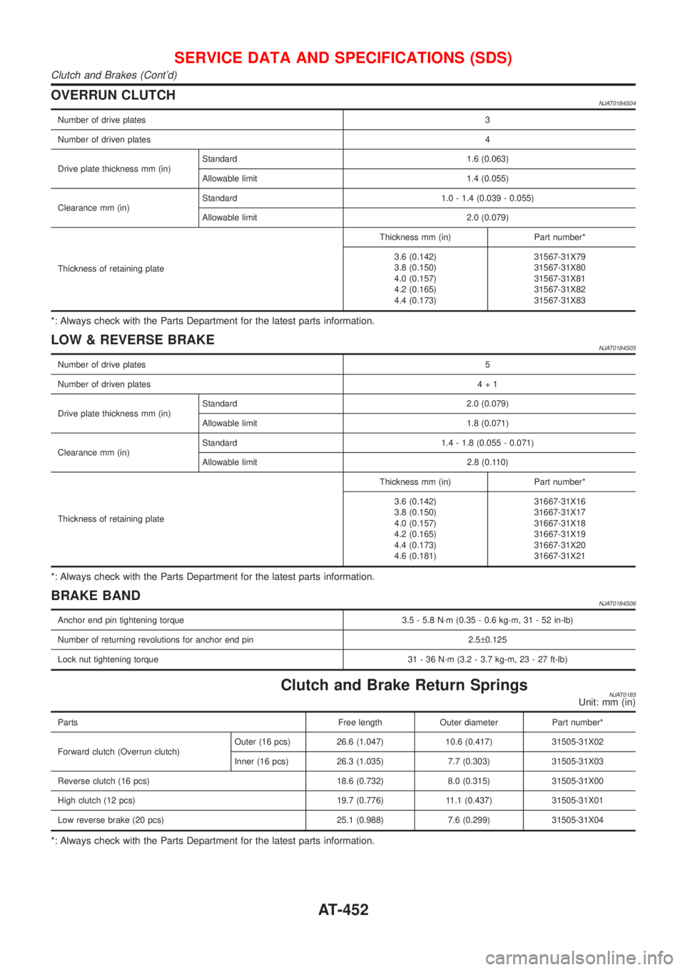
OVERRUN CLUTCHNJAT0184S04
Number of drive plates3
Number of driven plates4
Drive plate thickness mm (in)Standard 1.6 (0.063)
Allowable limit 1.4 (0.055)
Clearance mm (in)Standard 1.0 - 1.4 (0.039 - 0.055)
Allowable limit 2.0 (0.079)
Thickness of retaining plateThickness mm (in) Part number*
3.6 (0.142)
3.8 (0.150)
4.0 (0.157)
4.2 (0.165)
4.4 (0.173)31567-31X79
31567-31X80
31567-31X81
31567-31X82
31567-31X83
*: Always check with the Parts Department for the latest parts information.
LOW & REVERSE BRAKENJAT0184S05
Number of drive plates5
Number of driven plates4+1
Drive plate thickness mm (in)Standard 2.0 (0.079)
Allowable limit 1.8 (0.071)
Clearance mm (in)Standard 1.4 - 1.8 (0.055 - 0.071)
Allowable limit 2.8 (0.110)
Thickness of retaining plateThickness mm (in) Part number*
3.6 (0.142)
3.8 (0.150)
4.0 (0.157)
4.2 (0.165)
4.4 (0.173)
4.6 (0.181)31667-31X16
31667-31X17
31667-31X18
31667-31X19
31667-31X20
31667-31X21
*: Always check with the Parts Department for the latest parts information.
BRAKE BANDNJAT0184S06
Anchor end pin tightening torque 3.5 - 5.8 N´m (0.35 - 0.6 kg-m, 31 - 52 in-lb)
Number of returning revolutions for anchor end pin 2.5±0.125
Lock nut tightening torque 31 - 36 N´m (3.2 - 3.7 kg-m, 23 - 27 ft-lb)
Clutch and Brake Return SpringsNJAT0185Unit: mm (in)
Parts Free length Outer diameter Part number*
Forward clutch (Overrun clutch)Outer (16 pcs) 26.6 (1.047) 10.6 (0.417) 31505-31X02
Inner (16 pcs) 26.3 (1.035) 7.7 (0.303) 31505-31X03
Reverse clutch (16 pcs) 18.6 (0.732) 8.0 (0.315) 31505-31X00
High clutch (12 pcs) 19.7 (0.776) 11.1 (0.437) 31505-31X01
Low reverse brake (20 pcs) 25.1 (0.988) 7.6 (0.299) 31505-31X04
*: Always check with the Parts Department for the latest parts information.
SERVICE DATA AND SPECIFICATIONS (SDS)
Clutch and Brakes (Cont'd)
AT-452