2001 NISSAN ALMERA N16 service
[x] Cancel search: servicePage 1194 of 2493
AAT470A
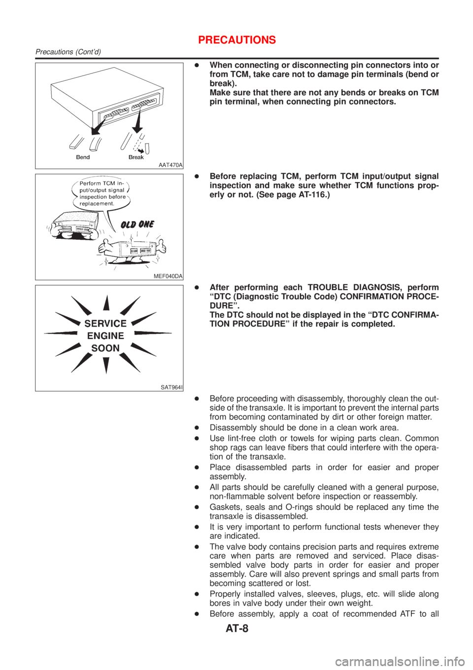
+When connecting or disconnecting pin connectors into or
from TCM, take care not to damage pin terminals (bend or
break).
Make sure that there are not any bends or breaks on TCM
pin terminal, when connecting pin connectors.
MEF040DA
+Before replacing TCM, perform TCM input/output signal
inspection and make sure whether TCM functions prop-
erly or not. (See page AT-116.)
SAT964I
+After performing each TROUBLE DIAGNOSIS, perform
ªDTC (Diagnostic Trouble Code) CONFIRMATION PROCE-
DUREº.
The DTC should not be displayed in the ªDTC CONFIRMA-
TION PROCEDUREº if the repair is completed.
+Before proceeding with disassembly, thoroughly clean the out-
side of the transaxle. It is important to prevent the internal parts
from becoming contaminated by dirt or other foreign matter.
+Disassembly should be done in a clean work area.
+Use lint-free cloth or towels for wiping parts clean. Common
shop rags can leave fibers that could interfere with the opera-
tion of the transaxle.
+Place disassembled parts in order for easier and proper
assembly.
+All parts should be carefully cleaned with a general purpose,
non-flammable solvent before inspection or reassembly.
+Gaskets, seals and O-rings should be replaced any time the
transaxle is disassembled.
+It is very important to perform functional tests whenever they
are indicated.
+The valve body contains precision parts and requires extreme
care when parts are removed and serviced. Place disas-
sembled valve body parts in order for easier and proper
assembly. Care will also prevent springs and small parts from
becoming scattered or lost.
+Properly installed valves, sleeves, plugs, etc. will slide along
bores in valve body under their own weight.
+Before assembly, apply a coat of recommended ATF to all
PRECAUTIONS
Precautions (Cont'd)
AT-8
Page 1195 of 2493
parts. Apply petroleum jelly to protect O-rings and seals, or
hold bearings and washers in place during assembly. Do not
use grease.
+Extreme care should be taken to avoid damage to O-rings,
seals and gaskets when assembling.
+After overhaul, refill the transaxle with new ATF.
+When the A/T drain plug is removed, only some of the fluid is
drained. Old A/T fluid will remain in torque converter and ATF
cooling system.
Always follow the procedures under ªChanging A/T Fluidº in the
AT section when changing A/T fluid. Refer to ªChanging A/T
Fluidº, AT-15.
Service Notice or PrecautionsNJAT0247FAIL-SAFENJAT0247S01The TCM has an electronic Fail-Safe (limp home mode). This allows the vehicle to be driven even if a major
electrical input/output device circuit is damaged.
Under Fail-Safe, the vehicle always runs in third gear, even with a shift lever position of ª1º, ª2º or ªDº. The
customer may complain of sluggish or poor acceleration.
When the ignition key is turned ªONº following Fail-Safe operation, O/D OFF indicator lamp blinks for about
8 seconds. (For EXCEPT FOR EURO-OBD; ªSELF-DIAGNOSTIC PROCEDURE (WITHOUT CONSULT-II)º,
refer to AT-42 and for EURO-OBD; ªTCM SELF-DIAGNOSTIC PROCEDURE (No Tools)º, refer to AT-61.)
Fail-Safe may occur without electrical circuit damage if the vehicle is driven under extreme conditions (such
as excessive wheel spin followed by sudden braking). To recover normal shift pattern, turn the ignition key
ªOFFº for 5 seconds, then ªONº.
The blinking of the O/D OFF indicator lamp for about 8 seconds will appear only once and be cleared. The
customer may resume normal driving conditions.
Always follow the ªWORK FLOWº [Refer to AT-71 (Except for Euro-OBD), AT-76 (EURO-OBD).]
The SELF-DIAGNOSIS results will be as follows:
The first SELF-DIAGNOSIS will indicate damage to the vehicle speed sensor or the revolution sensor.
During the next SELF-DIAGNOSIS, performed after checking the sensor, no damages will be indicated.
TORQUE CONVERTER SERVICENJAT0247S02The torque converter should be replaced under any of the following conditions:
+External leaks in the hub weld area.
+Converter hub is scored or damaged.
+Converter pilot is broken, damaged or fits poorly into crankshaft.
+Steel particles are found after flushing the cooler and cooler lines.
+Pump is damaged or steel particles are found in the converter.
+Vehicle has TCC shudder and/or no TCC apply. Replace only after all hydraulic and electrical diagnoses
have been made. (Converter clutch material may be glazed.)
+Converter is contaminated with engine coolant containing antifreeze.
+Internal failure of stator roller clutch.
+Heavy clutch debris due to overheating (blue converter).
+Steel particles or clutch lining material found in fluid filter or on magnet when no internal parts in unit are
worn or damaged Ð indicates that lining material came from converter.
The torque converter should not be replaced if:
PRECAUTIONS
Precautions (Cont'd)
AT-9
Page 1196 of 2493

+The fluid has an odor, is discolored, and there is no evidence of metal or clutch facing particles.
+The threads in one or more of the converter bolt holes are damaged.
+Transaxle failure did not display evidence of damaged or worn internal parts, steel particles or clutch plate
lining material in unit and inside the fluid filter.
+Vehicle has been exposed to high mileage (only). The exception may be where the torque converter clutch
dampener plate lining has seen excess wear by vehicles operated in heavy and/or constant traffic, such
as taxi, delivery or police use.
EURO-OBD SELF-DIAGNOSIS Ð EURO-OBD ÐNJAT0247S04+A/T self-diagnosis is performed by the TCM in combination with the ECM. The results can be read through
the blinking pattern of the O/D OFF indicator or the malfunction indicator (MI). Refer to the table on AT-53
for the indicator used to display each self-diagnostic result.
+The self-diagnostic results indicated by the MI are automatically stored in both the ECM and TCM memo-
ries.
Always perform the procedure ªHOW TO ERASE DTCº on AT-50 to complete the repair and avoid
unnecessary blinking of the MI.
+The following self-diagnostic items can be detected using ECM self-diagnostic results mode* only when
the O/D OFF indicator lamp does not indicate any malfunctions.
þ PNP switch
þ A/T 1st, 2nd, 3rd, or 4th gear function
*: For details of EURO-OBD, refer to EC-57, ªON BOARD DIAGNOSTIC SYSTEM DESCRIPTIONº.
+Certain systems and components, especially those related to EURO-OBD, may use a new style
slide-locking type harness connector.
For description and how to disconnect, refer to EL-5, ªHARNESS CONNECTORº.
Wiring Diagrams and Trouble DiagnosisNJAT0248When you read wiring diagrams, refer to the following:
+GI-12, ªHOW TO READ WIRING DIAGRAMSº
+EL-10, ªPOWER SUPPLY ROUTINGº
When you perform trouble diagnosis, refer to the following:
+GI-32, ªHOW TO FOLLOW TEST GROUP IN TROUBLE DIAGNOSISº
+GI-21, ªHOW TO PERFORM EFFICIENT DIAGNOSIS FOR AN ELECTRICAL INCIDENTº
PRECAUTIONS
Service Notice or Precautions (Cont'd)
AT-10
Page 1197 of 2493
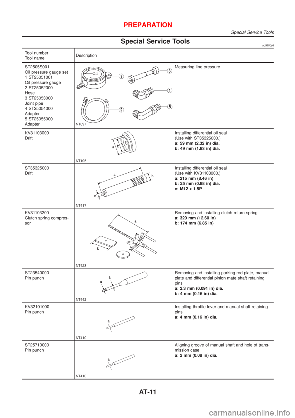
Special Service ToolsNJAT0006
Tool number
Tool nameDescription
ST2505S001
Oil pressure gauge set
1 ST25051001
Oil pressure gauge
2 ST25052000
Hose
3 ST25053000
Joint pipe
4 ST25054000
Adapter
5 ST25055000
Adapter
NT097
Measuring line pressure
KV31103000
Drift
NT105
Installing differential oil seal
(Use with ST35325000.)
a: 59 mm (2.32 in) dia.
b: 49 mm (1.93 in) dia.
ST35325000
Drift
NT417
Installing differential oil seal
(Use with KV31103000.)
a: 215 mm (8.46 in)
b: 25 mm (0.98 in) dia.
c: M12 x 1.5P
KV31103200
Clutch spring compres-
sor
NT423
Removing and installing clutch return spring
a: 320 mm (12.60 in)
b: 174 mm (6.85 in)
ST23540000
Pin punch
NT442
Removing and installing parking rod plate, manual
plate and differential pinion mate shaft retaining
pins
a: 2.3 mm (0.091 in) dia.
b: 4 mm (0.16 in) dia.
KV32101000
Pin punch
NT410
Installing throttle lever and manual shaft retaining
pins
a: 4 mm (0.16 in) dia.
ST25710000
Pin punch
NT410
Aligning groove of manual shaft and hole of trans-
mission case
a: 2 mm (0.08 in) dia.
PREPARATION
Special Service Tools
AT-11
Page 1198 of 2493
Tool number
Tool nameDescription
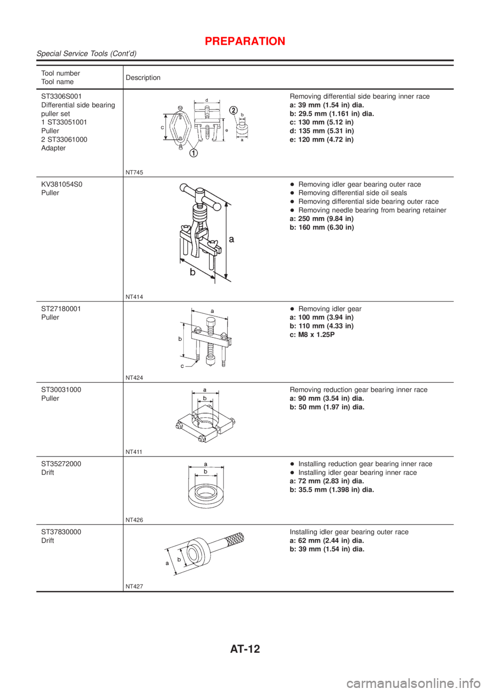
ST3306S001
Differential side bearing
puller set
1 ST33051001
Puller
2 ST33061000
Adapter
NT745
Removing differential side bearing inner race
a: 39 mm (1.54 in) dia.
b: 29.5 mm (1.161 in) dia.
c: 130 mm (5.12 in)
d: 135 mm (5.31 in)
e: 120 mm (4.72 in)
KV381054S0
Puller
NT414
+Removing idler gear bearing outer race
+Removing differential side oil seals
+Removing differential side bearing outer race
+Removing needle bearing from bearing retainer
a: 250 mm (9.84 in)
b: 160 mm (6.30 in)
ST27180001
Puller
NT424
+Removing idler gear
a: 100 mm (3.94 in)
b: 110 mm (4.33 in)
c: M8 x 1.25P
ST30031000
Puller
NT411
Removing reduction gear bearing inner race
a: 90 mm (3.54 in) dia.
b: 50 mm (1.97 in) dia.
ST35272000
Drift
NT426
+Installing reduction gear bearing inner race
+Installing idler gear bearing inner race
a: 72 mm (2.83 in) dia.
b: 35.5 mm (1.398 in) dia.
ST37830000
Drift
NT427
Installing idler gear bearing outer race
a: 62 mm (2.44 in) dia.
b: 39 mm (1.54 in) dia.
PREPARATION
Special Service Tools (Cont'd)
AT-12
Page 1199 of 2493
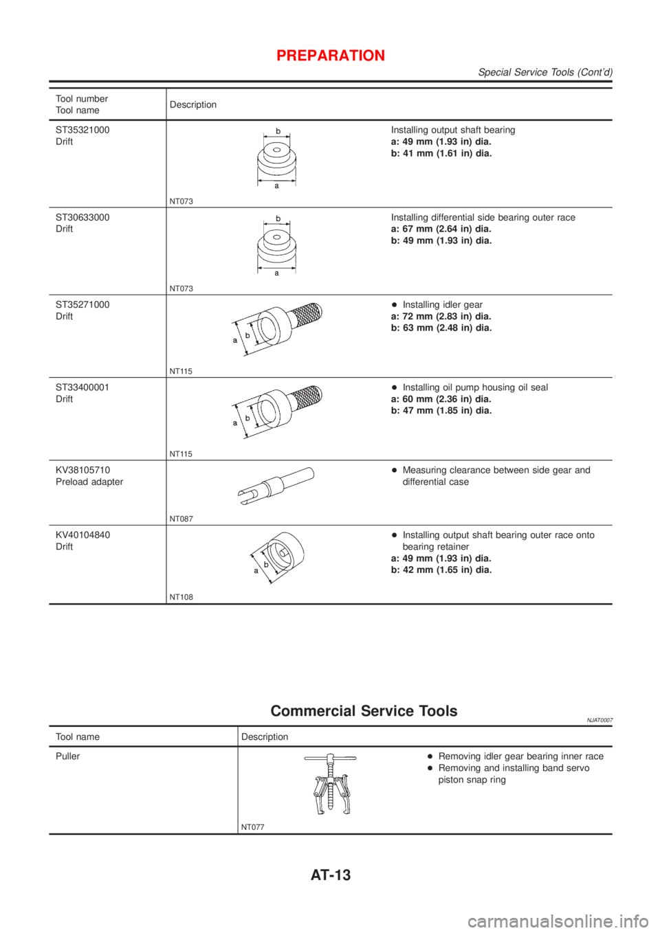
Tool number
Tool nameDescription
ST35321000
Drift
NT073
Installing output shaft bearing
a: 49 mm (1.93 in) dia.
b: 41 mm (1.61 in) dia.
ST30633000
Drift
NT073
Installing differential side bearing outer race
a: 67 mm (2.64 in) dia.
b: 49 mm (1.93 in) dia.
ST35271000
Drift
NT115
+Installing idler gear
a: 72 mm (2.83 in) dia.
b: 63 mm (2.48 in) dia.
ST33400001
Drift
NT115
+Installing oil pump housing oil seal
a: 60 mm (2.36 in) dia.
b: 47 mm (1.85 in) dia.
KV38105710
Preload adapter
NT087
+Measuring clearance between side gear and
differential case
KV40104840
Drift
NT108
+Installing output shaft bearing outer race onto
bearing retainer
a: 49 mm (1.93 in) dia.
b: 42 mm (1.65 in) dia.
Commercial Service ToolsNJAT0007
Tool name Description
Puller
NT077
+Removing idler gear bearing inner race
+Removing and installing band servo
piston snap ring
PREPARATION
Special Service Tools (Cont'd)
AT-13
Page 1200 of 2493
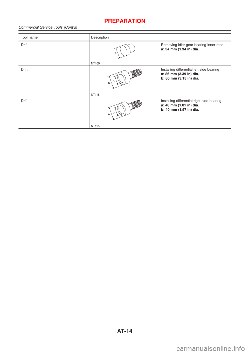
Tool name Description
Drift
NT109
Removing idler gear bearing inner race
a: 34 mm (1.34 in) dia.
Drift
NT115
Installing differential left side bearing
a: 86 mm (3.39 in) dia.
b: 80 mm (3.15 in) dia.
Drift
NT115
Installing differential right side bearing
a: 46 mm (1.81 in) dia.
b: 40 mm (1.57 in) dia.
PREPARATION
Commercial Service Tools (Cont'd)
AT-14
Page 1223 of 2493
CONSULT-IINJAT0022After performing ªSELF-DIAGNOSTIC PROCEDURE (WITH CON-
SULT-II)º (AT-37), place check marks for results on the ªDIAGNOS-
TIC WORKSHEETº, AT-69. Reference pages are provided follow-
ing the items.
NOTICE:
1) The CONSULT-II electrically displays shift timing and lock-up
timing (that is, operation timing of each solenoid).
Check for time difference between actual shift timing and the
CONSULT-II display. If the difference is noticeable, mechani-
cal parts (except solenoids, sensors, etc.) may be malfunction-
ing. Check mechanical parts using applicable diagnostic pro-
cedures.
2) Shift schedule (which implies gear position) displayed on
CONSULT-II and that indicated in Service Manual may differ
slightly. This occurs because of the following reasons:
+Actual shift schedule has more or less tolerance or allowance,
+Shift schedule indicated in Service Manual refers to the point
where shifts start, and
+Gear position displayed on CONSULT-II indicates the point
where shifts are completed.
3) Shift solenoid valve ªAº or ªBº is displayed on CONSULT-II at
the start of shifting. Gear position is displayed upon completion
of shifting (which is computed by TCM).
4) Additional CONSULT-II information can be found in the Opera-
tion Manual supplied with the CONSULT-II unit.
SAT580J
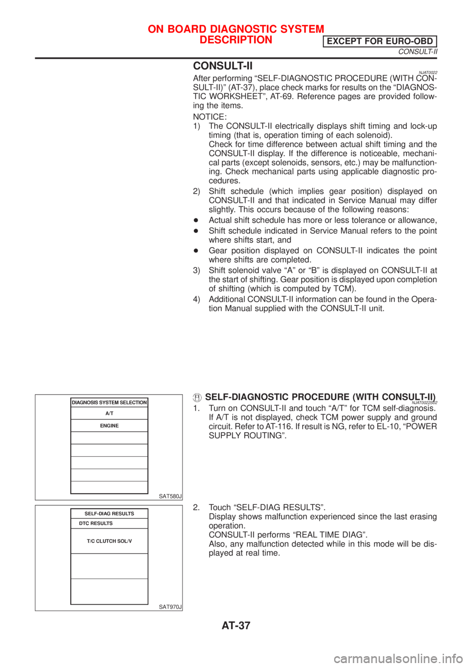
SELF-DIAGNOSTIC PROCEDURE (WITH CONSULT-II)NJAT0022S021. Turn on CONSULT-II and touch ªA/Tº for TCM self-diagnosis.
If A/T is not displayed, check TCM power supply and ground
circuit. Refer to AT-116. If result is NG, refer to EL-10, ªPOWER
SUPPLY ROUTINGº.
SAT970J
2. Touch ªSELF-DIAG RESULTSº.
Display shows malfunction experienced since the last erasing
operation.
CONSULT-II performs ªREAL TIME DIAGº.
Also, any malfunction detected while in this mode will be dis-
played at real time.
ON BOARD DIAGNOSTIC SYSTEM
DESCRIPTION
EXCEPT FOR EURO-OBD
CONSULT-II
AT-37