Page 1259 of 2395
SEL350X
Aiming AdjustmentNBEL0029Before performing aiming adjustment, make sure of the following.
1) Keep all tires inflated to correct pressure.
2) Place vehicle on level ground.
3) See that vehicle is unloaded (except for full levels of coolant,
engine oil and fuel, and spare tire, jack, and tools). Have the
driver or equivalent weight placed in driver's seat.
Adjust aiming in the vertical direction by turning the adjusting
screw.
MEL327G
1. Set the distance between the screen and the center of the fog
lamp lens as shown at left.
2. Turn front fog lamps ON.
MEL328GA
3. Adjust front fog lamps so that the top edge of the high inten-
sity zone is 200 mm (7.9 in) below the height of the fog lamp
centers as shown at left.
IWhen performing adjustment, if necessary, cover the head-
lamps and opposite fog lamp.
FRONT FOG LAMP
Aiming Adjustment
EL-74
Page 1642 of 2395
NBEL0145
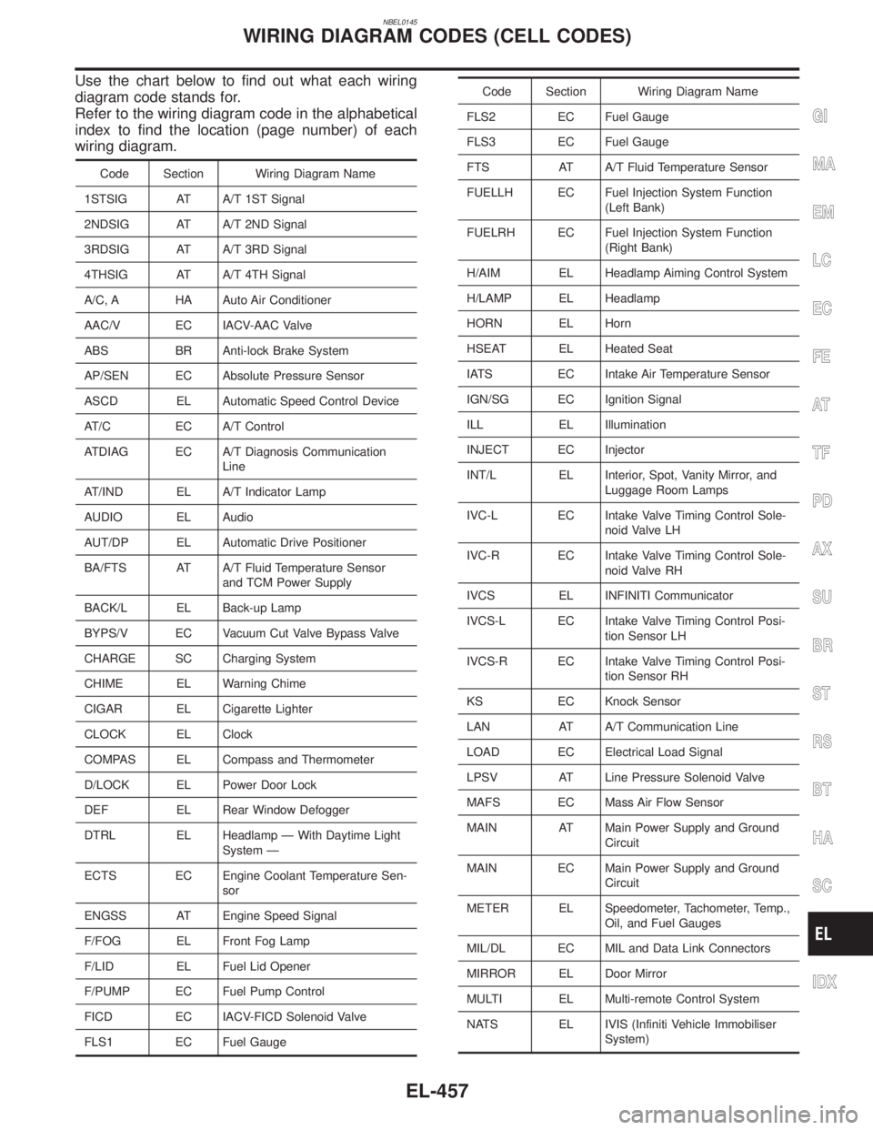
Use the chart below to find out what each wiring
diagram code stands for.
Refer to the wiring diagram code in the alphabetical
index to find the location (page number) of each
wiring diagram.
Code Section Wiring Diagram Name
1STSIG AT A/T 1ST Signal
2NDSIG AT A/T 2ND Signal
3RDSIG AT A/T 3RD Signal
4THSIG AT A/T 4TH Signal
A/C, A HA Auto Air Conditioner
AAC/V EC IACV-AAC Valve
ABS BR Anti-lock Brake System
AP/SEN EC Absolute Pressure Sensor
ASCD EL Automatic Speed Control Device
AT/C EC A/T Control
ATDIAG EC A/T Diagnosis Communication
Line
AT/IND EL A/T Indicator Lamp
AUDIO EL Audio
AUT/DP EL Automatic Drive Positioner
BA/FTS AT A/T Fluid Temperature Sensor
and TCM Power Supply
BACK/L EL Back-up Lamp
BYPS/V EC Vacuum Cut Valve Bypass Valve
CHARGE SC Charging System
CHIME EL Warning Chime
CIGAR EL Cigarette Lighter
CLOCK EL Clock
COMPAS EL Compass and Thermometer
D/LOCK EL Power Door Lock
DEF EL Rear Window Defogger
DTRL EL Headlamp Ð With Daytime Light
System Ð
ECTS EC Engine Coolant Temperature Sen-
sor
ENGSS AT Engine Speed Signal
F/FOG EL Front Fog Lamp
F/LID EL Fuel Lid Opener
F/PUMP EC Fuel Pump Control
FICD EC IACV-FICD Solenoid Valve
FLS1 EC Fuel Gauge
Code Section Wiring Diagram Name
FLS2 EC Fuel Gauge
FLS3 EC Fuel Gauge
FTS AT A/T Fluid Temperature Sensor
FUELLH EC Fuel Injection System Function
(Left Bank)
FUELRH EC Fuel Injection System Function
(Right Bank)
H/AIM EL Headlamp Aiming Control System
H/LAMP EL Headlamp
HORN EL Horn
HSEAT EL Heated Seat
IATS EC Intake Air Temperature Sensor
IGN/SG EC Ignition Signal
ILL EL Illumination
INJECT EC Injector
INT/L EL Interior, Spot, Vanity Mirror, and
Luggage Room Lamps
IVC-L EC Intake Valve Timing Control Sole-
noid Valve LH
IVC-R EC Intake Valve Timing Control Sole-
noid Valve RH
IVCS EL INFINITI Communicator
IVCS-L EC Intake Valve Timing Control Posi-
tion Sensor LH
IVCS-R EC Intake Valve Timing Control Posi-
tion Sensor RH
KS EC Knock Sensor
LAN AT A/T Communication Line
LOAD EC Electrical Load Signal
LPSV AT Line Pressure Solenoid Valve
MAFS EC Mass Air Flow Sensor
MAIN AT Main Power Supply and Ground
Circuit
MAIN EC Main Power Supply and Ground
Circuit
METER EL Speedometer, Tachometer, Temp.,
Oil, and Fuel Gauges
MIL/DL EC MIL and Data Link Connectors
MIRROR EL Door Mirror
MULTI EL Multi-remote Control System
NATS EL IVIS (Infiniti Vehicle Immobiliser
System)
GI
MA
EM
LC
EC
FE
AT
TF
PD
AX
SU
BR
ST
RS
BT
HA
SC
IDX
WIRING DIAGRAM CODES (CELL CODES)
EL-457
Page 1653 of 2395
Removal and InstallationNBEM0006
SEM483G
1. Intake manifold collector support
2. Lower intake manifold collector
3. Fuel damper and fuel feed hose
assembly
4. Injector
5. Fuel tube assembly6. Fuel pressure regulator
7. Ignition coil with power transistor
8. Upper intake manifold collector
9. Intake manifold
10. Throttle body11. IACV-AAC valve
12. EVAP canister purge volume con-
trol solenoid valve
13. Swirl control valve
14. Variable induction air control valve
control actuator
OUTER COMPONENT PARTS
Removal and Installation
EM-10
Page 1657 of 2395

NBEM0007
SEM480G
SEM481G
JEM482G
SEM387C
1. Warm up engine.
2. Turn ignition switch OFF.
3. Release fuel pressure.
Refer to EC-39, ªFuel Pressure Releaseº.
4. Remove engine cover and throttle wire.
5. Remove air duct with air cleaner case.
6. Remove harness connectors and harness brackets around
ignition coils.
7. Remove throttle body.
8. Disconnect ignition coil with power transistor harness
connectors, then remove ignition coils.
9. Remove all spark plugs.
IClean area around plug with compressed air before removing
the spark plug.
10. Attach a compression tester to No. 1 cylinder.
11. Depress accelerator pedal fully to keep throttle valve wide
open.
12. Crank engine and record highest gauge indication.
13. Repeat the measurement on each cylinder as shown above.
IAlways use a fully-charged battery to obtain specified
engine speed.
Unit: kPa (kg/cm2, psi)/rpm
Standard MinimumDifference limit between
cylinders
1,275 (13.0, 185)/300 981 (10.0, 142)/300 98 (1.0, 14)/300
14. If compression in one or more cylinders is low:
a. Pour a small amount of engine oil into cylinders through spark
plug holes.
b. Retest compression.
IIf adding oil helps compression, piston rings may be worn
or damaged. If so, replace piston rings after checking pis-
ton.
IIf pressure stays low, a valve may be sticking or seating
improperly. Inspect and repair valve and valve seat. (Refer
to SDS, EM-76 and EM-79.) If valve or valve seat is dam-
aged excessively, replace them.
IIf compression stays low in two cylinders that are next to
each other:
a) The cylinder head gasket may be leaking, or
b) Both cylinders may have valve component damage. Inspect
and repair as necessary.
15. Install parts in reverse order of removal.
16. Perform ªSelf-diagnosis Procedureº referring to EC-72, ªHow to
Erase DTCº if any DTC appears.
MEASUREMENT OF COMPRESSION PRESSURE
EM-14
Page 1659 of 2395
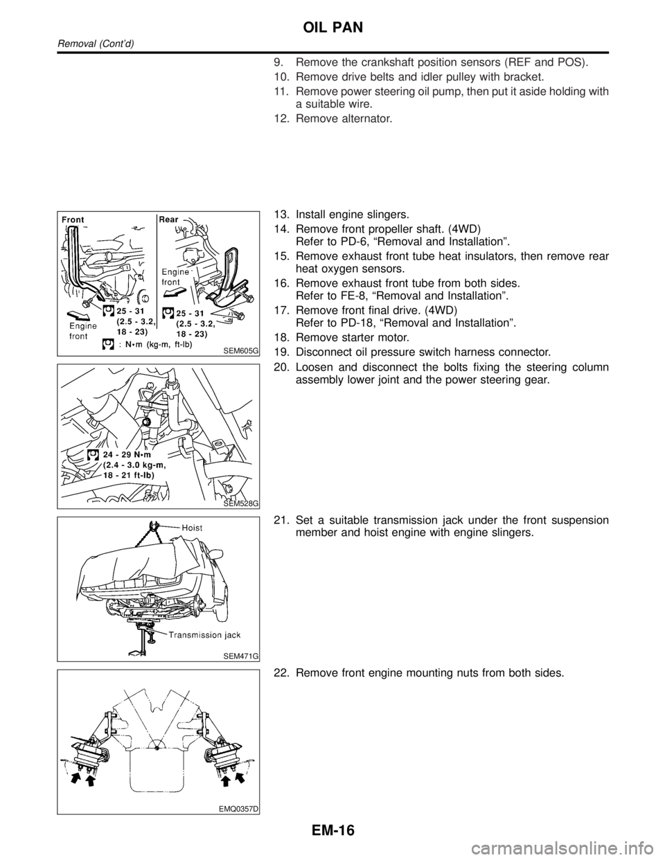
9. Remove the crankshaft position sensors (REF and POS).
10. Remove drive belts and idler pulley with bracket.
11. Remove power steering oil pump, then put it aside holding with
a suitable wire.
12. Remove alternator.
SEM605G
13. Install engine slingers.
14. Remove front propeller shaft. (4WD)
Refer to PD-6, ªRemoval and Installationº.
15. Remove exhaust front tube heat insulators, then remove rear
heat oxygen sensors.
16. Remove exhaust front tube from both sides.
Refer to FE-8, ªRemoval and Installationº.
17. Remove front final drive. (4WD)
Refer to PD-18, ªRemoval and Installationº.
18. Remove starter motor.
19. Disconnect oil pressure switch harness connector.
SEM528G
20. Loosen and disconnect the bolts fixing the steering column
assembly lower joint and the power steering gear.
SEM471G
21. Set a suitable transmission jack under the front suspension
member and hoist engine with engine slingers.
EMQ0357D
22. Remove front engine mounting nuts from both sides.
OIL PAN
Removal (Cont'd)
EM-16
Page 1666 of 2395
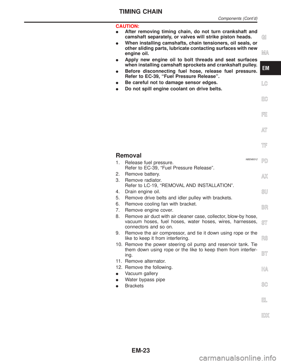
CAUTION:
IAfter removing timing chain, do not turn crankshaft and
camshaft separately, or valves will strike piston heads.
IWhen installing camshafts, chain tensioners, oil seals, or
other sliding parts, lubricate contacting surfaces with new
engine oil.
IApply new engine oil to bolt threads and seat surfaces
when installing camshaft sprockets and crankshaft pulley.
IBefore disconnecting fuel hose, release fuel pressure.
Refer to EC-39, ªFuel Pressure Releaseº.
IBe careful not to damage sensor edges.
IDo not spill engine coolant on drive belts.
RemovalNBEM00121. Release fuel pressure.
Refer to EC-39, ªFuel Pressure Releaseº.
2. Remove battery.
3. Remove radiator.
Refer to LC-19, ªREMOVAL AND INSTALLATIONº.
4. Drain engine oil.
5. Remove drive belts and idler pulley with brackets.
6. Remove cooling fan with bracket.
7. Remove engine cover.
8. Remove air duct with air cleaner case, collector, blow-by hose,
vacuum hoses, fuel hoses, water hoses, wires, harnesses,
connectors and so on.
9. Remove the air compressor, and tie it down using rope or the
like to keep it from interfering.
10. Remove the power steering oil pump and reservoir tank. Tie
them down using rope or the like to keep them from interfer-
ing.
11. Remove alternator.
12. Remove the following.
IVacuum gallery
IWater bypass pipe
IBrackets
GI
MA
LC
EC
FE
AT
TF
PD
AX
SU
BR
ST
RS
BT
HA
SC
EL
IDX
TIMING CHAIN
Components (Cont'd)
EM-23
Page 1678 of 2395
SEM948E
ReplacementNBEM0015CAUTION:
When removing the oil pans, oil pump assembly and timing
chain from engine, first remove the camshaft position sensor
(PHASE), CVTC sensor and the crankshaft position sensors
(REF)/(POS) from the assembly.
Be careful not to damage sensor edges.
VALVE OIL SEALNBEM0015S011. Remove timing chain. Refer to ªRemoval, EM-23.
2. Remove camshaft brackets and camshaft. Refer to
ªDisassemblyº, EM-41.
3. Remove valve lifters and shims.
4. Remove valve spring with Tool.
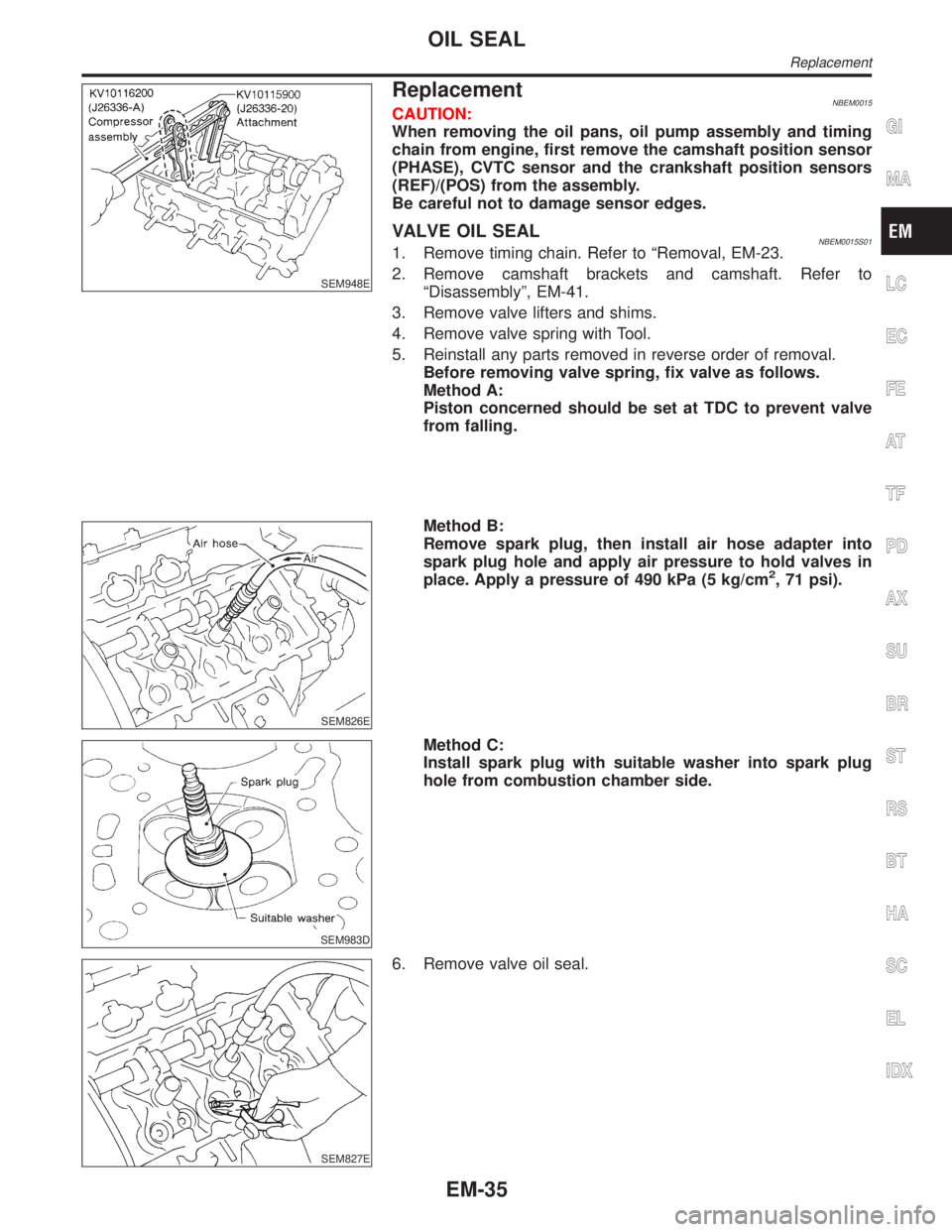
5. Reinstall any parts removed in reverse order of removal.
Before removing valve spring, fix valve as follows.
Method A:
Piston concerned should be set at TDC to prevent valve
from falling.
SEM826E
Method B:
Remove spark plug, then install air hose adapter into
spark plug hole and apply air pressure to hold valves in
place. Apply a pressure of 490 kPa (5 kg/cm
2, 71 psi).
SEM983D
Method C:
Install spark plug with suitable washer into spark plug
hole from combustion chamber side.
SEM827E
6. Remove valve oil seal.
GI
MA
LC
EC
FE
AT
TF
PD
AX
SU
BR
ST
RS
BT
HA
SC
EL
IDX
OIL SEAL
Replacement
EM-35
Page 1702 of 2395
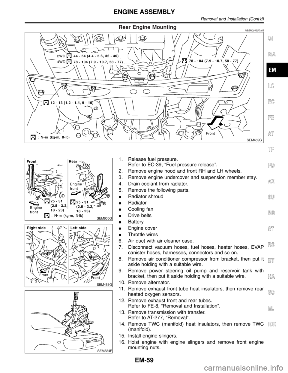
Rear Engine MountingNBEM0042S0102
SEM459G
SEM605G
SEM461G
SEM324F
1. Release fuel pressure.
Refer to EC-39, ªFuel pressure releaseº.
2. Remove engine hood and front RH and LH wheels.
3. Remove engine undercover and suspension member stay.
4. Drain coolant from radiator.
5. Remove the following parts.
IRadiator shroud
IRadiator
ICooling fan
IDrive belts
IBattery
IEngine cover
IThrottle wires
6. Air duct with air cleaner case.
7. Disconnect vacuum hoses, fuel hoses, heater hoses, EVAP
canister hoses, harnesses, connectors and so on.
8. Remove air conditioner compressor from bracket, then put it
aside holding with a suitable wire.
9. Remove power steering oil pump and reservoir tank with
bracket, then put it aside holding with a suitable wire.
10. Remove alternator.
11. Remove exhaust front tube heat insulators, then remove rear
heated oxygen sensors.
12. Remove exhaust front and rear tubes.
Refer to FE-8, ªRemoval and Installationº.
13. Remove transmission with transfer.
Refer to AT-277, ªRemovalº.
14. Remove TWC (manifold) heat insulators, then remove TWC
(manifold).
15. Install engine slingers.
16. Hoist engine with engine slingers and remove front engine
mounting nuts.
GI
MA
LC
EC
FE
AT
TF
PD
AX
SU
BR
ST
RS
BT
HA
SC
EL
IDX
ENGINE ASSEMBLY
Removal and Installation (Cont'd)
EM-59