2001 INFINITI QX4 low oil pressure
[x] Cancel search: low oil pressurePage 2237 of 2395

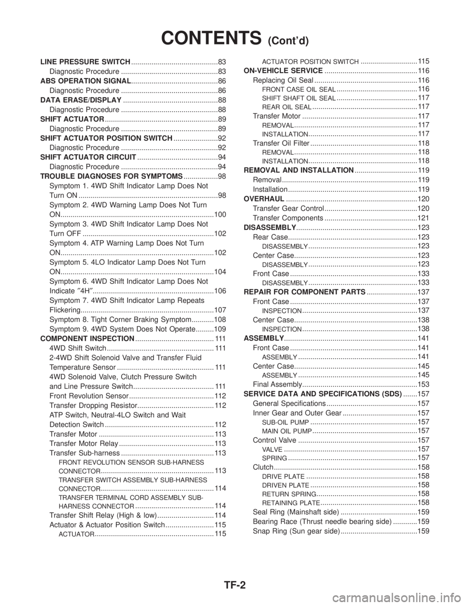
LINE PRESSURE SWITCH...........................................83
Diagnostic Procedure ................................................83
ABS OPERATION SIGNAL...........................................86
Diagnostic Procedure ................................................86
DATA ERASE/DISPLAY...............................................88
Diagnostic Procedure ................................................88
SHIFT ACTUATOR........................................................89
Diagnostic Procedure ................................................89
SHIFT ACTUATOR POSITION SWITCH......................92
Diagnostic Procedure ................................................92
SHIFT ACTUATOR CIRCUIT........................................94
Diagnostic Procedure ................................................94
TROUBLE DIAGNOSES FOR SYMPTOMS.................98
Symptom 1. 4WD Shift Indicator Lamp Does Not
Turn ON .....................................................................98
Symptom 2. 4WD Warning Lamp Does Not Turn
ON............................................................................100
Symptom 3. 4WD Shift Indicator Lamp Does Not
Turn OFF .................................................................102
Symptom 4. ATP Warning Lamp Does Not Turn
ON............................................................................102
Symptom 5. 4LO Indicator Lamp Does Not Turn
ON............................................................................104
Symptom 6. 4WD Shift Indicator Lamp Does Not
Indicate²4H²............................................................106
Symptom 7. 4WD Shift Indicator Lamp Repeats
Flickering..................................................................107
Symptom 8. Tight Corner Braking Symptom...........108
Symptom 9. 4WD System Does Not Operate.........109
COMPONENT INSPECTION....................................... 111
4WD Shift Switch ..................................................... 111
2-4WD Shift Solenoid Valve and Transfer Fluid
Temperature Sensor ................................................ 111
4WD Solenoid Valve, Clutch Pressure Switch
and Line Pressure Switch........................................ 111
Front Revolution Sensor .......................................... 112
Transfer Dropping Resistor...................................... 112
ATP Switch, Neutral-4LO Switch and Wait
Detection Switch ...................................................... 112
Transfer Motor ......................................................... 113
Transfer Motor Relay ............................................... 113
Transfer Sub-harness .............................................. 113
FRONT REVOLUTION SENSOR SUB-HARNESS
CONNECTOR
........................................................ 113
TRANSFER SWITCH ASSEMBLY SUB-HARNESS
CONNECTOR
........................................................ 114
TRANSFER TERMINAL CORD ASSEMBLY SUB-
HARNESS CONNECTOR
....................................... 114
Transfer Shift Relay (High & low) ............................ 114
Actuator & Actuator Position Switch ........................ 115
ACTUATOR........................................................... 115
ACTUATOR POSITION SWITCH............................ 115
ON-VEHICLE SERVICE.............................................. 116
Replacing Oil Seal ................................................... 116
FRONT CASE OIL SEAL........................................ 116
SHIFT SHAFT OIL SEAL........................................ 117
REAR OIL SEAL.................................................... 117
Transfer Motor ......................................................... 117
REMOVAL............................................................. 117
INSTALLATION...................................................... 117
Transfer Oil Filter ..................................................... 118
REMOVAL............................................................. 118
INSTALLATION...................................................... 118
REMOVAL AND INSTALLATION............................... 119
Removal ................................................................... 119
Installation ................................................................ 119
OVERHAUL.................................................................120
Transfer Gear Control ..............................................120
Transfer Components ..............................................121
DISASSEMBLY............................................................123
Rear Case................................................................123
DISASSEMBLY......................................................123
Center Case.............................................................123
DISASSEMBLY......................................................123
Front Case ...............................................................133
DISASSEMBLY......................................................133
REPAIR FOR COMPONENT PARTS.........................137
Front Case ...............................................................137
INSPECTION.........................................................137
Center Case.............................................................138
INSPECTION.........................................................138
ASSEMBLY..................................................................141
Front Case ...............................................................141
ASSEMBLY...........................................................141
Center Case.............................................................145
ASSEMBLY...........................................................145
Final Assembly.........................................................153
SERVICE DATA AND SPECIFICATIONS (SDS).......157
General Specifications .............................................157
Inner Gear and Outer Gear .....................................157
SUB-OIL PUMP.....................................................157
MAIN OIL PUMP....................................................157
Control Valve ...........................................................157
VALVE..................................................................157
SPRING................................................................157
Clutch .......................................................................158
DRIVE PLATE.......................................................158
DRIVEN PLATE.....................................................158
RETURN SPRING..................................................158
RETAINING PLATE................................................158
Seal Ring (Mainshaft side) ......................................159
Bearing Race (Thrust needle bearing side) ............159
Snap Ring (Sun gear side) ......................................159
CONTENTS(Cont'd)
TF-2
Page 2250 of 2395

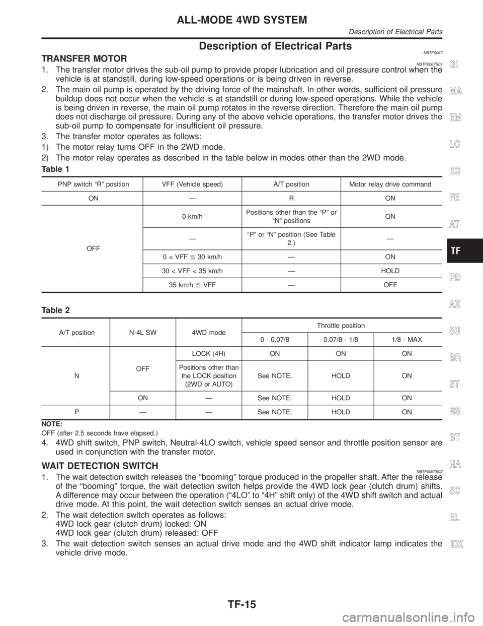
Description of Electrical PartsNBTF0067TRANSFER MOTORNBTF0067S011. The transfer motor drives the sub-oil pump to provide proper lubrication and oil pressure control when the
vehicle is at standstill, during low-speed operations or is being driven in reverse.
2. The main oil pump is operated by the driving force of the mainshaft. In other words, sufficient oil pressure
buildup does not occur when the vehicle is at standstill or during low-speed operations. While the vehicle
is being driven in reverse, the main oil pump rotates in the reverse direction. Therefore the main oil pump
does not discharge oil pressure. During any of the above vehicle operations, the transfer motor drives the
sub-oil pump to compensate for insufficient oil pressure.
3. The transfer motor operates as follows:
1) The motor relay turns OFF in the 2WD mode.
2) The motor relay operates as described in the table below in modes other than the 2WD mode.
Table 1
PNP switch ªRº position VFF (Vehicle speed) A/T position Motor relay drive command
ON Ð R ON
OFF0 km/hPositions other than the ªPº or
ªNº positionsON
ЪPº or ªNº position (See Table
2.)Ð
0 < VFF%30 km/h Ð ON
30 < VFF < 35 km/h Ð HOLD
35 km/h%VFF Ð OFF
Table 2
A/T position N-4L SW 4WD modeThrottle position
0 - 0.07/8 0.07/8 - 1/8 1/8 - MAX
NOFFLOCK (4H) ON ON ON
Positions other than
the LOCK position
(2WD or AUTO)See NOTE. HOLD ON
ON Ð See NOTE. HOLD ON
P Ð Ð See NOTE. HOLD ON
NOTE:
OFF (after 2.5 seconds have elapsed.)
4. 4WD shift switch, PNP switch, Neutral-4LO switch, vehicle speed sensor and throttle position sensor are
used in conjunction with the transfer motor.
WAIT DETECTION SWITCHNBTF0067S021. The wait detection switch releases the ªboomingº torque produced in the propeller shaft. After the release
of the ªboomingº torque, the wait detection switch helps provide the 4WD lock gear (clutch drum) shifts.
A difference may occur between the operation (ª4LOº to ª4Hº shift only) of the 4WD shift switch and actual
drive mode. At this point, the wait detection switch senses an actual drive mode.
2. The wait detection switch operates as follows:
4WD lock gear (clutch drum) locked: ON
4WD lock gear (clutch drum) released: OFF
3. The wait detection switch senses an actual drive mode and the 4WD shift indicator lamp indicates the
vehicle drive mode.
GI
MA
EM
LC
EC
FE
AT
PD
AX
SU
BR
ST
RS
BT
HA
SC
EL
IDX
ALL-MODE 4WD SYSTEM
Description of Electrical Parts
TF-15
Page 2344 of 2395

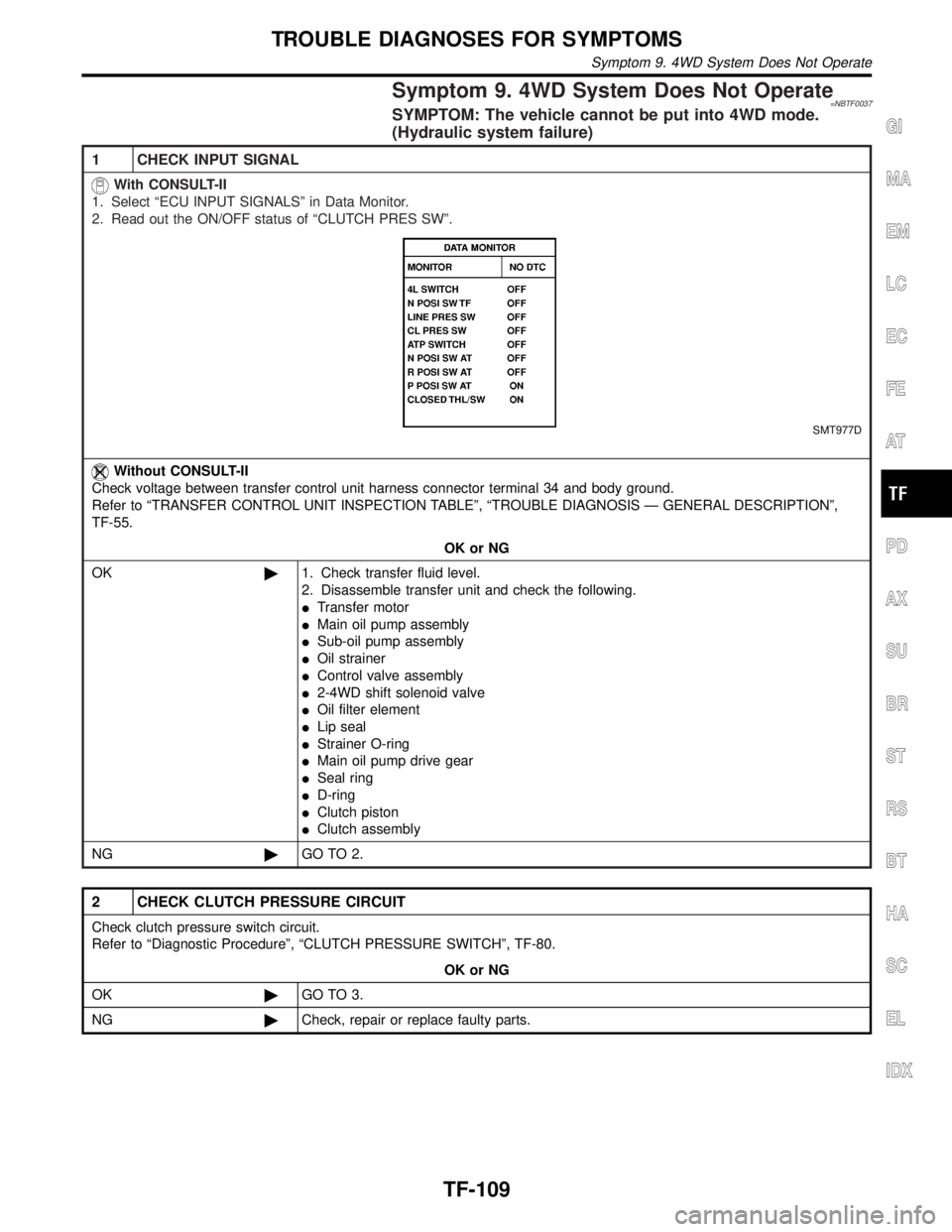
Symptom 9. 4WD System Does Not Operate=NBTF0037SYMPTOM: The vehicle cannot be put into 4WD mode.
(Hydraulic system failure)
1 CHECK INPUT SIGNAL
With CONSULT-II
1. Select ªECU INPUT SIGNALSº in Data Monitor.
2. Read out the ON/OFF status of ªCLUTCH PRES SWº.
SMT977D
Without CONSULT-II
Check voltage between transfer control unit harness connector terminal 34 and body ground.
Refer to ªTRANSFER CONTROL UNIT INSPECTION TABLEº, ªTROUBLE DIAGNOSIS Ð GENERAL DESCRIPTIONº,
TF-55.
OK or NG
OK©1. Check transfer fluid level.
2. Disassemble transfer unit and check the following.
ITransfer motor
IMain oil pump assembly
ISub-oil pump assembly
IOil strainer
IControl valve assembly
I2-4WD shift solenoid valve
IOil filter element
ILip seal
IStrainer O-ring
IMain oil pump drive gear
ISeal ring
ID-ring
IClutch piston
IClutch assembly
NG©GO TO 2.
2 CHECK CLUTCH PRESSURE CIRCUIT
Check clutch pressure switch circuit.
Refer to ªDiagnostic Procedureº, ªCLUTCH PRESSURE SWITCHº, TF-80.
OK or NG
OK©GO TO 3.
NG©Check, repair or replace faulty parts.
GI
MA
EM
LC
EC
FE
AT
PD
AX
SU
BR
ST
RS
BT
HA
SC
EL
IDX
TROUBLE DIAGNOSES FOR SYMPTOMS
Symptom 9. 4WD System Does Not Operate
TF-109