2001 INFINITI QX4 low oil pressure
[x] Cancel search: low oil pressurePage 1965 of 2395
LSV (Load sensing valve) ..............................BR-12
Lubricant (R134a) A/C..................................HA-146
Lubricants .......................................................MA-11
Lubrication circuit (engine) ...............................LC-3
Lubrication-locks, hinges and hood
latches ........................................................MA-27
Luggage room lamp ........................................EL-88
M
MAFS - Wiring diagram................................EC-154
Magnet clutch .......................................HA-104, 150
MAIN - Wiring diagram.................................EC-142
Main oil pump (Transfer)...............................TF-131
Mainshaft (Transfer) ......................................TF-125
Maintenance (engine) ....................................MA-13
MAJOR OVERHALL......................................AT-281
Major overhaul (Transfer) .............................TF-120
Malfunction indicator lamp (MIL) ....................EC-74
Mass air flow sensor (MAFS) .......................EC-150
Master cylinder (brake) ..................................BR-16
Meter ...............................................................EL-94
METER - Wiring diagram................................EL-99
MIL & Data link connectors circuit ...............EC-648
MIL/DL - Wiring diagram ..............................EC-648
MIRROR - Wiring diagram............................EL-177
Mirror defogger .............................................EL-151
Mirror, door......................................................BT-56
Mirror, out side ................................................BT-56
Misfire ...........................................................EC-320
Mode door control linkage adjustment ...........HA-81
Mode door motor ............................................HA-75
Model variation ................................................GI-41
Molding - See Exterior ....................................BT-35
MULTI - Wiring diagram ................................EL-274
Multi-remote control system..........................EL-270
Multiplex communication ..............................HA-142
Multiport fuel injection (MFI) system ..............EC-28
Multiport fuel injection precautions ....................GI-6
N
NATS (Nissan anti-theft system)...................EL-328
NATS (Nissan anti-theft system)
precautions ....................................................GI-3
NATS - Wiring diagram .................................EL-330
NAVI - wiring diagram ...................................EL-394
Navigation System ........................................EL-385
Neutral-4LO switch ........................................TF-112
NVH troubleshooting (AX) ..........................AX-3, 18
NVH troubleshooting (BR)................................BR-6
NVH troubleshooting (PD)................................PD-3
NVH troubleshooting (ST).................................ST-6
NVH troubleshooting (SU) .........................SU-3, 15O
Oil change (capacity) .....................................MA-11
Oil filter (Transfer) .........................................TF-118
Oil pan (engine) .............................................EM-15
Oil pressure (engine) ........................................LC-4
Oil pump (A/T) ...............................................AT-297
Oil pump (engine) .............................................LC-5
Oil pump regulator valve (engine) ....................LC-6
Oil seal replacement (engine)........................EM-35
Oil seal replacement (front final drive
4WD) ...........................................................PD-15
Oil seal replacement (front of final
drive) ...........................................................PD-40
On board diagnostic system ..........................EC-59
Out side mirror ................................................BT-56
Overdrive control switch ................................AT-263
Overrun clutch ...............................................AT-320
Overrun clutch solenoid valve .......................AT-189
P
P/ANT - Wiring diagram ................................EL-170
Park/Neutral position switch .........................EC-604
Park/neutral position switch (A/T) .........AT-103, 263
Parking brake control .....................................BR-30
Parking lamp ...................................................EL-61
PCV (positive crankcase ventilation) .............EC-38
PGC/V - Wiring diagram ......................EC-370, 544
PHASE - Wiring diagram .............................EC-342
Pinion bearing preload diff. ............................PD-25
Pinion gear height diff. .............................PD-25, 53
Piston assembly .............................................EM-71
Piston pin inspection ......................................EM-63
Piston ring inspection.....................................EM-64
Piston to bore clearance ................................EM-66
Planetary carrier (Transfer) ...........................TF-134
PNP/SW - Wiring diagram ...........................EC-607
POS - Wiring diagram ..................................EC-517
POWER - Wiring diagram...............................EL-10
Power antenna ..............................................EL-169
Power door lock ............................................EL-254
Power door mirror .........................................EL-177
Power seat ....................................................EL-181
Power steering fluid level .....................MA-27, ST-8
Power steering gear........................................ST-17
Power steering hydraulic pressure .................ST-10
Power steering oil pressure switch ..............EC-634
Power steering oil pump .................................ST-27
Power steering system bleeding.......................ST-9
Power supply routing ........................................EL-9
Power transistor & ignition coil.....................EC-499
Power window ...............................................EL-241
PRE/SE - Wiring diagram ............................EC-384
Precations for Leak detection dye ...................HA-3
Precautions (General) .......................................GI-5
Pressure test (A/T) ..........................................AT-62
Propeller shaft ..................................................PD-3
ALPHABETICAL INDEX
IDX-6
Page 1973 of 2395
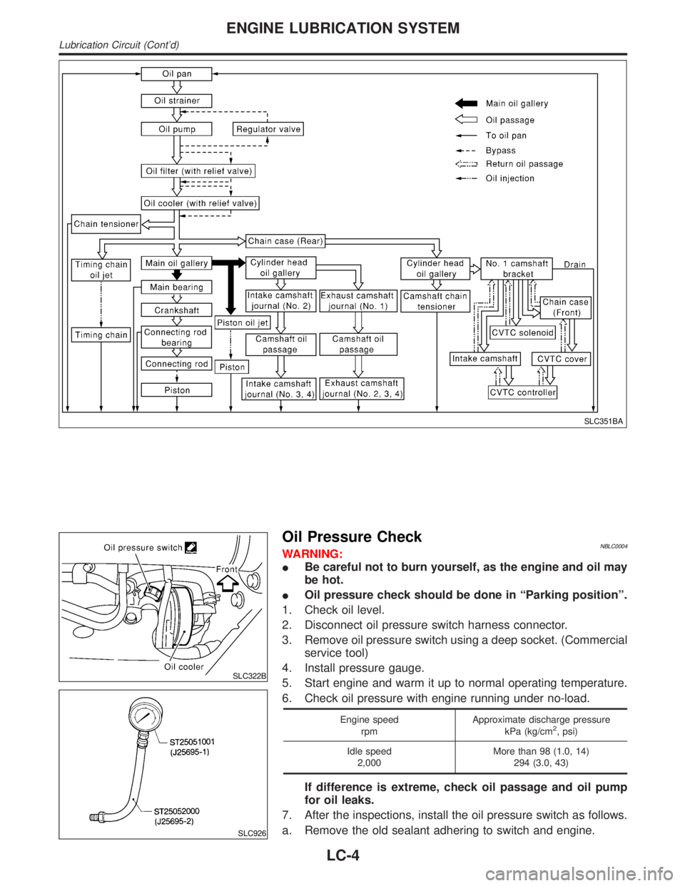
SLC351BA
SLC322B
SLC926
Oil Pressure CheckNBLC0004WARNING:
IBe careful not to burn yourself, as the engine and oil may
be hot.
IOil pressure check should be done in ªParking positionº.
1. Check oil level.
2. Disconnect oil pressure switch harness connector.
3. Remove oil pressure switch using a deep socket. (Commercial
service tool)
4. Install pressure gauge.
5. Start engine and warm it up to normal operating temperature.
6. Check oil pressure with engine running under no-load.
Engine speed
rpmApproximate discharge pressure
kPa (kg/cm2, psi)
Idle speed
2,000More than 98 (1.0, 14)
294 (3.0, 43)
If difference is extreme, check oil passage and oil pump
for oil leaks.
7. After the inspections, install the oil pressure switch as follows.
a. Remove the old sealant adhering to switch and engine.
ENGINE LUBRICATION SYSTEM
Lubrication Circuit (Cont'd)
LC-4
Page 1975 of 2395

SLC324B
SLC932A
SLC933A
SLC934AB
OIL PUMP INSPECTIONNBLC0007IInstall oil pump with the groove of the inner rotor facing
the oil pump cover.
Using a feeler gauge, straightedge and micrometers, check the
following clearances:
Unit: mm (in)
Body to outer rotor radial clearance 1 0.114 - 0.200 (0.0045 - 0.0079)
Inner rotor to outer gear tip clearance
2Below 0.18 (0.0071)
Body to inner rotor axial clearance 3 0.030 - 0.070 (0.0012 - 0.0028)
Body to outer rotor axial clearance 4 0.050 - 0.110 (0.0020 - 0.0043)
Inner rotor to brazed portion of hous-
ing clearance 50.045 - 0.091 (0.0018 - 0.0036)
IIf the tip clearance (2) exceeds the limit, replace rotor set.
IIf body to rotor clearances (1, 3, 4, 5) exceed the limit,
replace oil pump body assembly.
SLC251B
REGULATOR VALVE INSPECTIONNBLC00081. Visually inspect components for wear and damage.
2. Check oil pressure regulator valve sliding surface and valve
spring.
3. Coat regulator valve with engine oil. Check that it falls
smoothly into the valve hole by its own weight.
If damaged, replace regulator valve set or oil pump body.
ENGINE LUBRICATION SYSTEM
Oil Pump (Cont'd)
LC-6
Page 1977 of 2395
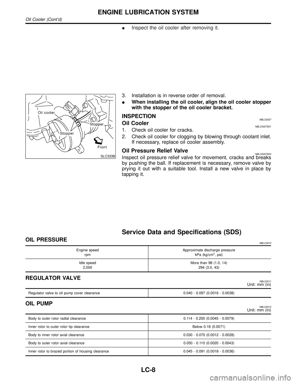
IInspect the oil cooler after removing it.
SLC333B
3. Installation is in reverse order of removal.
IWhen installing the oil cooler, align the oil cooler stopper
with the stopper of the oil cooler bracket.
INSPECTIONNBLC0037Oil CoolerNBLC0037S011. Check oil cooler for cracks.
2. Check oil cooler for clogging by blowing through coolant inlet.
If necessary, replace oil cooler assembly.
Oil Pressure Relief ValveNBLC0037S02Inspect oil pressure relief valve for movement, cracks and breaks
by pushing the ball. If replacement is necessary, remove valve by
prying it out with a suitable tool. Install a new valve in place by
tapping it.
Service Data and Specifications (SDS)
OIL PRESSURENBLC0010
Engine speed
rpmApproximate discharge pressure
kPa (kg/cm2, psi)
Idle speed
2,000More than 98 (1.0, 14)
294 (3.0, 43)
REGULATOR VALVENBLC0011Unit: mm (in)
Regulator valve to oil pump cover clearance 0.040 - 0.097 (0.0016 - 0.0038)
OIL PUMPNBLC0012Unit: mm (in)
Body to outer rotor radial clearance 0.114 - 0.200 (0.0045 - 0.0079)
Inner rotor to outer rotor tip clearance Below 0.18 (0.0071)
Body to inner rotor axial clearance 0.030 - 0.070 (0.0012 - 0.0028)
Body to outer rotor axial clearance 0.050 - 0.110 (0.0020 - 0.0043)
Inner rotor to brazed portion of housing clearance 0.045 - 0.091 (0.0018 - 0.0036)
ENGINE LUBRICATION SYSTEM
Oil Cooler (Cont'd)
LC-8
Page 1978 of 2395
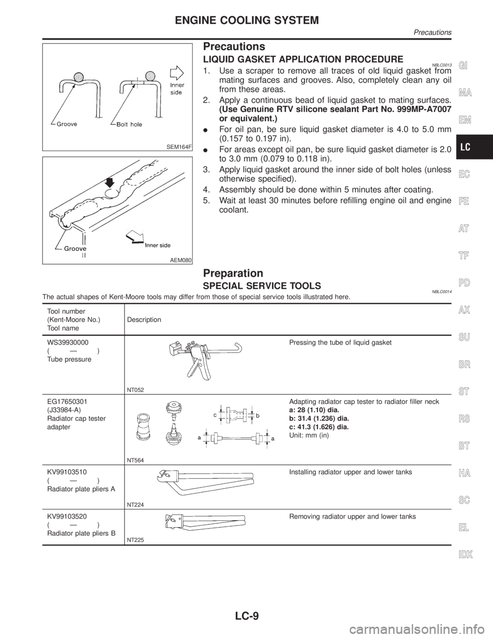
SEM164F
AEM080
Precautions
LIQUID GASKET APPLICATION PROCEDURENBLC00131. Use a scraper to remove all traces of old liquid gasket from
mating surfaces and grooves. Also, completely clean any oil
from these areas.
2. Apply a continuous bead of liquid gasket to mating surfaces.
(Use Genuine RTV silicone sealant Part No. 999MP-A7007
or equivalent.)
IFor oil pan, be sure liquid gasket diameter is 4.0 to 5.0 mm
(0.157 to 0.197 in).
IFor areas except oil pan, be sure liquid gasket diameter is 2.0
to 3.0 mm (0.079 to 0.118 in).
3. Apply liquid gasket around the inner side of bolt holes (unless
otherwise specified).
4. Assembly should be done within 5 minutes after coating.
5. Wait at least 30 minutes before refilling engine oil and engine
coolant.
Preparation
SPECIAL SERVICE TOOLSNBLC0014The actual shapes of Kent-Moore tools may differ from those of special service tools illustrated here.
Tool number
(Kent-Moore No.)
Tool nameDescription
WS39930000
(Ð)
Tube pressure
NT052
Pressing the tube of liquid gasket
EG17650301
(J33984-A)
Radiator cap tester
adapter
NT564
Adapting radiator cap tester to radiator filler neck
a: 28 (1.10) dia.
b: 31.4 (1.236) dia.
c: 41.3 (1.626) dia.
Unit: mm (in)
KV99103510
(Ð)
Radiator plate pliers A
NT224
Installing radiator upper and lower tanks
KV99103520
(Ð)
Radiator plate pliers B
NT225
Removing radiator upper and lower tanks
GI
MA
EM
EC
FE
AT
TF
PD
AX
SU
BR
ST
RS
BT
HA
SC
EL
IDX
ENGINE COOLING SYSTEM
Precautions
LC-9
Page 1984 of 2395
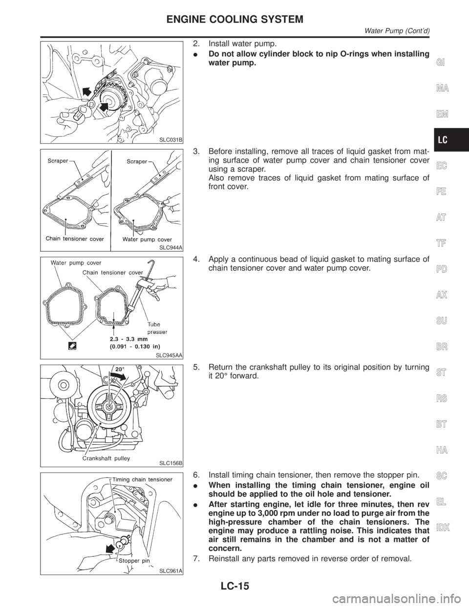
SLC031B
2. Install water pump.
IDo not allow cylinder block to nip O-rings when installing
water pump.
SLC944A
3. Before installing, remove all traces of liquid gasket from mat-
ing surface of water pump cover and chain tensioner cover
using a scraper.
Also remove traces of liquid gasket from mating surface of
front cover.
SLC945AA
4. Apply a continuous bead of liquid gasket to mating surface of
chain tensioner cover and water pump cover.
SLC156B
5. Return the crankshaft pulley to its original position by turning
it 20É forward.
SLC961A
6. Install timing chain tensioner, then remove the stopper pin.
IWhen installing the timing chain tensioner, engine oil
should be applied to the oil hole and tensioner.
IAfter starting engine, let idle for three minutes, then rev
engine up to 3,000 rpm under no load to purge air from the
high-pressure chamber of the chain tensioners. The
engine may produce a rattling noise. This indicates that
air still remains in the chamber and is not a matter of
concern.
7. Reinstall any parts removed in reverse order of removal.
GI
MA
EM
EC
FE
AT
TF
PD
AX
SU
BR
ST
RS
BT
HA
SC
EL
IDX
ENGINE COOLING SYSTEM
Water Pump (Cont'd)
LC-15
Page 2019 of 2395
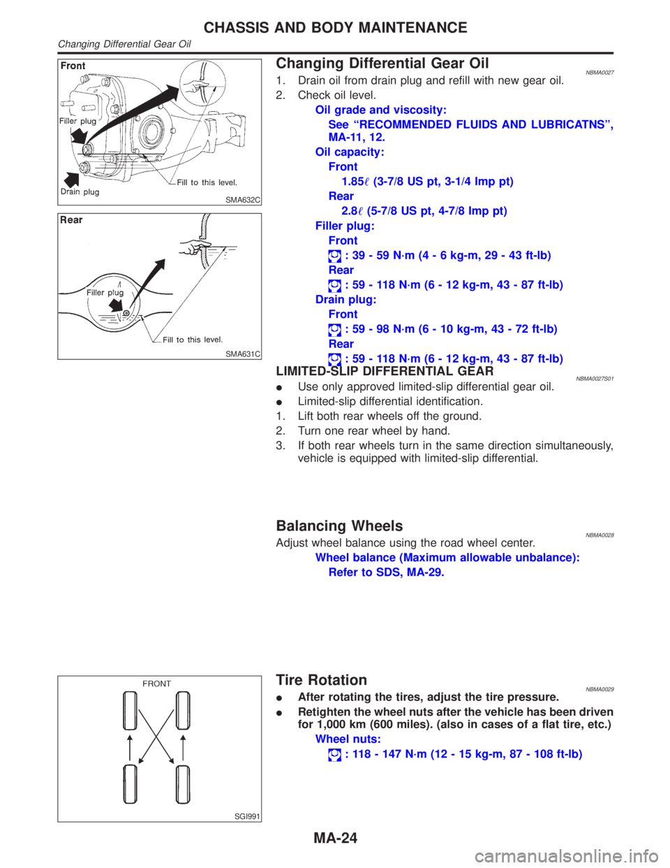
SMA632C
SMA631C
Changing Differential Gear OilNBMA00271. Drain oil from drain plug and refill with new gear oil.
2. Check oil level.
Oil grade and viscosity:
See ªRECOMMENDED FLUIDS AND LUBRICATNSº,
MA-11, 12.
Oil capacity:
Front
1.85(3-7/8 US pt, 3-1/4 Imp pt)
Rear
2.8(5-7/8 US pt, 4-7/8 Imp pt)
Filler plug:
Front
: 39 - 59 N´m (4 - 6 kg-m, 29 - 43 ft-lb)
Rear
: 59 - 118 N´m (6 - 12 kg-m, 43 - 87 ft-lb)
Drain plug:
Front
: 59 - 98 N´m (6 - 10 kg-m, 43 - 72 ft-lb)
Rear
: 59 - 118 N´m (6 - 12 kg-m, 43 - 87 ft-lb)
LIMITED-SLIP DIFFERENTIAL GEARNBMA0027S01IUse only approved limited-slip differential gear oil.
ILimited-slip differential identification.
1. Lift both rear wheels off the ground.
2. Turn one rear wheel by hand.
3. If both rear wheels turn in the same direction simultaneously,
vehicle is equipped with limited-slip differential.
Balancing WheelsNBMA0028Adjust wheel balance using the road wheel center.
Wheel balance (Maximum allowable unbalance):
Refer to SDS, MA-29.
SGI991
Tire RotationNBMA0029IAfter rotating the tires, adjust the tire pressure.
IRetighten the wheel nuts after the vehicle has been driven
for 1,000 km (600 miles). (also in cases of a flat tire, etc.)
Wheel nuts:
: 118 - 147 N´m (12 - 15 kg-m, 87 - 108 ft-lb)
CHASSIS AND BODY MAINTENANCE
Changing Differential Gear Oil
MA-24
Page 2190 of 2395
CAUTION:
Do not hold the steering wheel in a locked position for more
than 15 seconds.
4. If fluid leakage at connectors is noticed, loosen flare nut and
then retighten.
Do not overtighten connector as this can damage O-ring,
washer and connector.
5. Check rack boots for accumulation of power steering fluid.
Bleeding Hydraulic SystemNBST00131. Raise front end of vehicle until wheels are clear of the ground.
2. Add fluid into oil tank to specified level. Then, quickly turn
steering wheel fully to right and left and lightly touch steering
stoppers.
Repeat steering wheel operation until fluid level no longer
decreases.
3. Start engine.
Repeat step 2 above.
IIncomplete air bleeding will cause the following to occur. When
this happens, bleed air again.
a) Air bubbles in reservoir tank
b) Clicking noise in oil pump
c) Excessive buzzing in oil pump
Fluid noise may occur in the valve or oil pump. This is common
when the vehicle is stationary or while turning steering wheel
slowly. This does not affect performance or durability of the system.
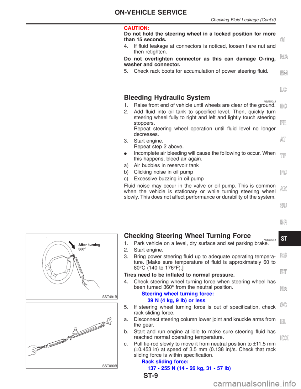
SST491B
SST090B
Checking Steering Wheel Turning ForceNBST00141. Park vehicle on a level, dry surface and set parking brake.
2. Start engine.
3. Bring power steering fluid up to adequate operating tempera-
ture. [Make sure temperature of fluid is approximately 60 to
80ÉC (140 to 176ÉF).]
Tires need to be inflated to normal pressure.
4. Check steering wheel turning force when steering wheel has
been turned 360É from the neutral position.
Steering wheel turning force:
39 N (4 kg, 9 lb) or less
5. If steering wheel turning force is out of specification, check
rack sliding force.
a. Disconnect steering column lower joint and knuckle arms from
the gear.
b. Start and run engine at idle to make sure steering fluid has
reached normal operating temperature.
c. Pull tie-rod slowly to move it from neutral position to±11.5 mm
(±0.453 in) at speed of 3.5 mm (0.138 in)/s. Check that rack
sliding force is within specification.
Rack sliding force:
137 - 255 N (14 - 26 kg, 31 - 57 lb)
GI
MA
EM
LC
EC
FE
AT
TF
PD
AX
SU
BR
RS
BT
HA
SC
EL
IDX
ON-VEHICLE SERVICE
Checking Fluid Leakage (Cont'd)
ST-9