2001 INFINITI QX4 lock
[x] Cancel search: lockPage 1999 of 2395

NBMA0003
General maintenance includes those items which should be checked during the normal day-to-day operation
of the vehicle. They are essential if the vehicle is to continue operating properly. The owners can perform
checks and inspections themselves or they can have their INFINITI dealers do them.
OUTSIDE THE VEHICLE
The maintenance items listed here should be performed from time to time, unless otherwise specified.
ItemReference page
TiresCheck the pressure with a gauge periodically when at a service station,
including the spare, and adjust to the specified pressure if necessary. Check
carefully for damage, cuts or excessive wear.Ð
Wheel nutsWhen checking the tires, make sure no nuts are missing, and check for any
loose nuts. Tighten if necessary.Ð
Tire rotationTires should be rotated every 12,000 km (7,500 miles). MA-24
Wheel alignment and
balanceIf the vehicle pulls to either side while driving on a straight and level road, or
if you detect uneven or abnormal tire wear, there may be a need for wheel
alignment. If the steering wheel or seat vibrates at normal highway speeds,
wheel balancing may be needed.MA-24, SU-6, ªFront
Wheel Alignmentº
Windshield wiper
bladesCheck for cracks or wear if they do not wipe properly. Ð
Doors and engine
hoodCheck that all doors and the engine hood operate smoothly as well as the
trunk lid and back hatch. Also make sure that all latches lock securely. Lubri-
cate if necessary. Make sure that the secondary latch keeps the hood from
opening when the primary latch is released.
When driving in areas using road salt or other corrosive materials, check
lubrication frequently.MA-27
INSIDE THE VEHICLE
The maintenance items listed here should be checked on a regular basis, such as when performing periodic maintenance, cleaning the
vehicle, etc.
ItemReference page
LampsMake sure that the headlamps, stop lamps, tail lamps, turn signal lamps, and
other lamps are all operating properly and installed securely. Also check
headlamp aim.Ð
Warning lamps and
buzzers/chimesMake sure that all warning lamps and buzzers/chimes are operating properly. Ð
Windshield wiper
and washerCheck that the wipers and washer operate properly and that the wipers do
not streak.Ð
Windshield defrosterCheck that the air comes out of the defroster outlets properly and in sufficient
quantity when operating the heater or air conditioning.Ð
Steering wheelCheck that it has the specified play. Be sure to check for changes in the
steering condition, such as excessive play, hard steering or strange noises.
Free play: Less than 35 mm (1.38 in)Ð
SeatsCheck seat position controls such as seat adjusters, seatback recliner, etc. to
make sure they operate smoothly and that all latches lock securely in every
position. Check that the head restrains move up and down smoothly and that
the locks (if equipped) hold securely in all latched positions. Check that the
latches lock securely for folding-down rear seatbacks.Ð
Seat beltsCheck that all parts of the seat belt system (e.g. buckles, anchors, adjusters
and retractors) operate properly and smoothly and are installed securely.
Check the belt webbing for cuts, fraying, wear or damage.MA-28, RS-7, ªSeat Belt
Inspectionº
BrakesCheck that the brake does not pull the vehicle to one side when applied. Ð
GENERAL MAINTENANCE
MA-4
Page 2000 of 2395
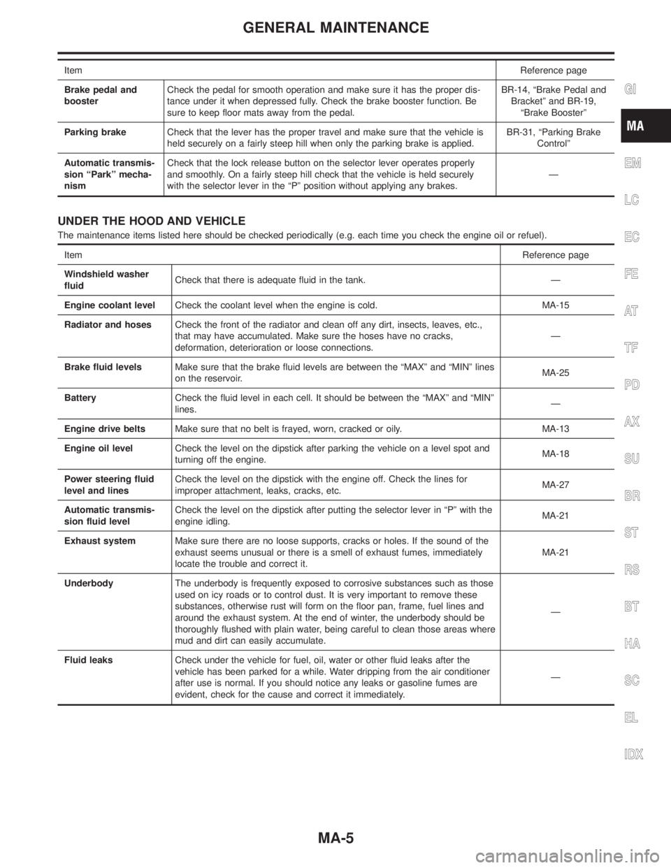
ItemReference page
Brake pedal and
boosterCheck the pedal for smooth operation and make sure it has the proper dis-
tance under it when depressed fully. Check the brake booster function. Be
sure to keep floor mats away from the pedal.BR-14, ªBrake Pedal and
Bracketº and BR-19,
ªBrake Boosterº
Parking brakeCheck that the lever has the proper travel and make sure that the vehicle is
held securely on a fairly steep hill when only the parking brake is applied.BR-31, ªParking Brake
Controlº
Automatic transmis-
sion ªParkº mecha-
nismCheck that the lock release button on the selector lever operates properly
and smoothly. On a fairly steep hill check that the vehicle is held securely
with the selector lever in the ªPº position without applying any brakes.Ð
UNDER THE HOOD AND VEHICLE
The maintenance items listed here should be checked periodically (e.g. each time you check the engine oil or refuel).
ItemReference page
Windshield washer
fluidCheck that there is adequate fluid in the tank. Ð
Engine coolant levelCheck the coolant level when the engine is cold. MA-15
Radiator and hosesCheck the front of the radiator and clean off any dirt, insects, leaves, etc.,
that may have accumulated. Make sure the hoses have no cracks,
deformation, deterioration or loose connections.Ð
Brake fluid levelsMake sure that the brake fluid levels are between the ªMAXº and ªMINº lines
on the reservoir.MA-25
BatteryCheck the fluid level in each cell. It should be between the ªMAXº and ªMINº
lines.Ð
Engine drive beltsMake sure that no belt is frayed, worn, cracked or oily. MA-13
Engine oil levelCheck the level on the dipstick after parking the vehicle on a level spot and
turning off the engine.MA-18
Power steering fluid
level and linesCheck the level on the dipstick with the engine off. Check the lines for
improper attachment, leaks, cracks, etc.MA-27
Automatic transmis-
sion fluid levelCheck the level on the dipstick after putting the selector lever in ªPº with the
engine idling.MA-21
Exhaust systemMake sure there are no loose supports, cracks or holes. If the sound of the
exhaust seems unusual or there is a smell of exhaust fumes, immediately
locate the trouble and correct it.MA-21
UnderbodyThe underbody is frequently exposed to corrosive substances such as those
used on icy roads or to control dust. It is very important to remove these
substances, otherwise rust will form on the floor pan, frame, fuel lines and
around the exhaust system. At the end of winter, the underbody should be
thoroughly flushed with plain water, being careful to clean those areas where
mud and dirt can easily accumulate.Ð
Fluid leaksCheck under the vehicle for fuel, oil, water or other fluid leaks after the
vehicle has been parked for a while. Water dripping from the air conditioner
after use is normal. If you should notice any leaks or gasoline fumes are
evident, check for the cause and correct it immediately.Ð
GI
EM
LC
EC
FE
AT
TF
PD
AX
SU
BR
ST
RS
BT
HA
SC
EL
IDX
GENERAL MAINTENANCE
MA-5
Page 2009 of 2395
SMA857C
SMA858C
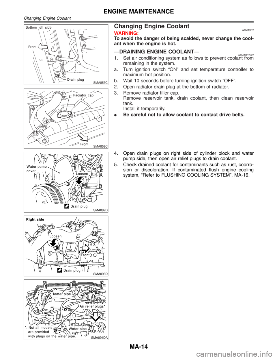
Changing Engine CoolantNBMA0011WARNING:
To avoid the danger of being scalded, never change the cool-
ant when the engine is hot.
ÐDRAINING ENGINE COOLANTÐNBMA0011S011. Set air conditioning system as follows to prevent coolant from
remaining in the system.
a. Turn ignition switch ªONº and set temperature controller to
maximum hot position.
b. Wait 10 seconds before turning ignition switch ªOFFº.
2. Open radiator drain plug at the bottom of radiator.
3. Remove radiator filler cap.
Remove reservoir tank, drain coolant, then clean reservoir
tank.
Install it temporarily.
IBe careful not to allow coolant to contact drive belts.
SMA092D
SMA093D
SMA094DA
4. Open drain plugs on right side of cylinder block and water
pump side, then open air relief plugs to drain coolant.
5. Check drained coolant for contaminants such as rust, coorro-
sion or discoloration. If contaminated flush engine cooling
system, ªRefer to FLUSHING COOLING SYSTEMº, MA-16.
ENGINE MAINTENANCE
Changing Engine Coolant
MA-14
Page 2010 of 2395
SMA182B
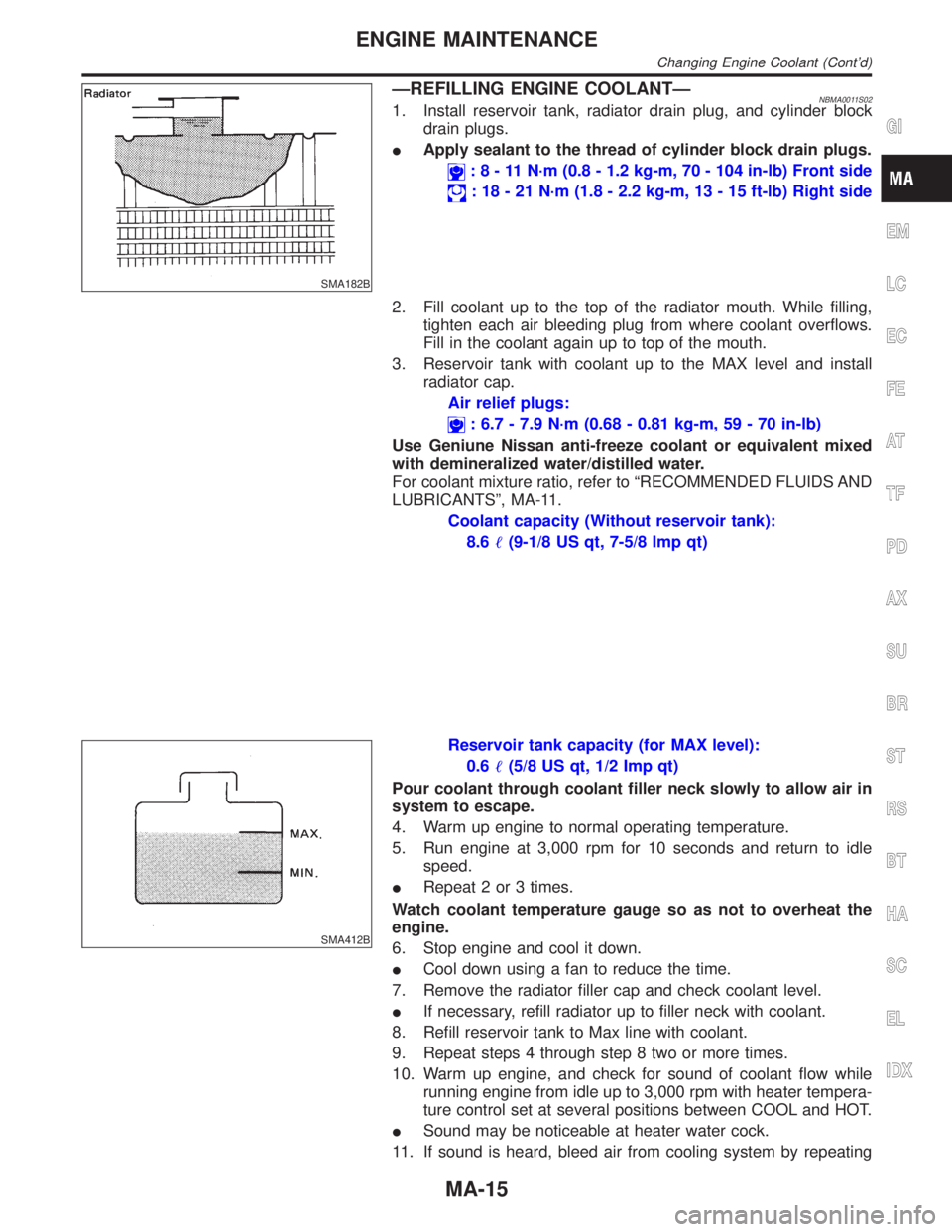
ÐREFILLING ENGINE COOLANTÐNBMA0011S021. Install reservoir tank, radiator drain plug, and cylinder block
drain plugs.
IApply sealant to the thread of cylinder block drain plugs.
:8-11N´m(0.8 - 1.2 kg-m, 70 - 104 in-lb) Front side
: 18 - 21 N´m (1.8 - 2.2 kg-m, 13 - 15 ft-lb) Right side
2. Fill coolant up to the top of the radiator mouth. While filling,
tighten each air bleeding plug from where coolant overflows.
Fill in the coolant again up to top of the mouth.
3. Reservoir tank with coolant up to the MAX level and install
radiator cap.
Air relief plugs:
: 6.7 - 7.9 N´m (0.68 - 0.81 kg-m, 59 - 70 in-lb)
Use Geniune Nissan anti-freeze coolant or equivalent mixed
with demineralized water/distilled water.
For coolant mixture ratio, refer to ªRECOMMENDED FLUIDS AND
LUBRICANTSº, MA-11.
Coolant capacity (Without reservoir tank):
8.6(9-1/8 US qt, 7-5/8 Imp qt)
SMA412B
Reservoir tank capacity (for MAX level):
0.6(5/8 US qt, 1/2 Imp qt)
Pour coolant through coolant filler neck slowly to allow air in
system to escape.
4. Warm up engine to normal operating temperature.
5. Run engine at 3,000 rpm for 10 seconds and return to idle
speed.
IRepeat 2 or 3 times.
Watch coolant temperature gauge so as not to overheat the
engine.
6. Stop engine and cool it down.
ICool down using a fan to reduce the time.
7. Remove the radiator filler cap and check coolant level.
IIf necessary, refill radiator up to filler neck with coolant.
8. Refill reservoir tank to Max line with coolant.
9. Repeat steps 4 through step 8 two or more times.
10. Warm up engine, and check for sound of coolant flow while
running engine from idle up to 3,000 rpm with heater tempera-
ture control set at several positions between COOL and HOT.
ISound may be noticeable at heater water cock.
11. If sound is heard, bleed air from cooling system by repeating
GI
EM
LC
EC
FE
AT
TF
PD
AX
SU
BR
ST
RS
BT
HA
SC
EL
IDX
ENGINE MAINTENANCE
Changing Engine Coolant (Cont'd)
MA-15
Page 2014 of 2395
SMA010
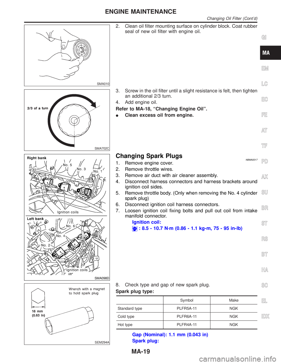
2. Clean oil filter mounting surface on cylinder block. Coat rubber
seal of new oil filter with engine oil.
SMA702C
3. Screw in the oil filter until a slight resistance is felt, then tighten
an additional 2/3 turn.
4. Add engine oil.
Refer to MA-18, ªChanging Engine Oilº.
IClean excess oil from engine.
SMA098D
Changing Spark PlugsNBMA00171. Remove engine cover.
2. Remove throttle wires.
3. Remove air duct with air cleaner assembly.
4. Disconnect harness connectors and harness brackets around
ignition coil sides.
5. Remove throttle body. (Only when removing the No. 4 cylinder
spark plug)
6. Disconnect ignition coil harness connectors.
7. Loosen ignition coil fixing bolts and pull out coil from intake
manifold connector.
Ignition coil:
: 8.5 - 10.7 N´m (0.86 - 1.1 kg-m, 75 - 95 in-lb)
SEM294A
8. Check type and gap of new spark plug.
Spark plug type:
Symbol Make
Standard type PLFR5A-11 NGK
Cold type PLFR6A-11 NGK
Hot type PLFR4A-11 NGK
Gap (Nominal): 1.1 mm (0.043 in)
Spark plug:
GI
EM
LC
EC
FE
AT
TF
PD
AX
SU
BR
ST
RS
BT
HA
SC
EL
IDX
ENGINE MAINTENANCE
Changing Oil Filter (Cont'd)
MA-19
Page 2022 of 2395
SST280B
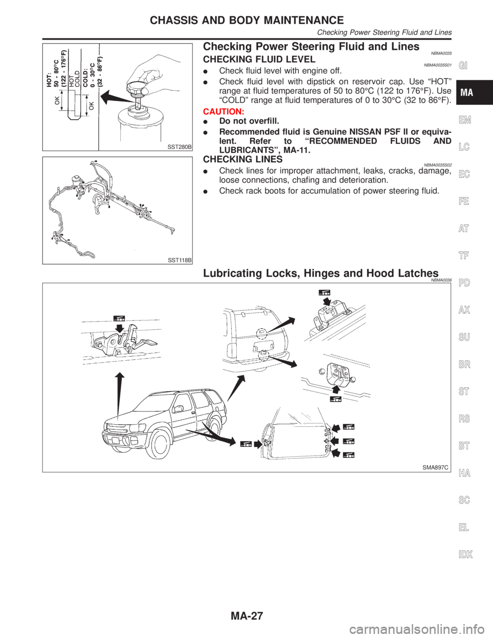
Checking Power Steering Fluid and LinesNBMA0035CHECKING FLUID LEVELNBMA0035S01ICheck fluid level with engine off.
ICheck fluid level with dipstick on reservoir cap. Use ªHOTº
range at fluid temperatures of 50 to 80ÉC (122 to 176ÉF). Use
ªCOLDº range at fluid temperatures of 0 to 30ÉC (32 to 86ÉF).
CAUTION:
IDo not overfill.
IRecommended fluid is Genuine NISSAN PSF II or equiva-
lent. Refer to ªRECOMMENDED FLUIDS AND
LUBRICANTSº, MA-11.
SST118B
CHECKING LINESNBMA0035S02ICheck lines for improper attachment, leaks, cracks, damage,
loose connections, chafing and deterioration.
ICheck rack boots for accumulation of power steering fluid.
Lubricating Locks, Hinges and Hood LatchesNBMA0036
SMA897C
GI
EM
LC
EC
FE
AT
TF
PD
AX
SU
BR
ST
RS
BT
HA
SC
EL
IDX
CHASSIS AND BODY MAINTENANCE
Checking Power Steering Fluid and Lines
MA-27
Page 2033 of 2395
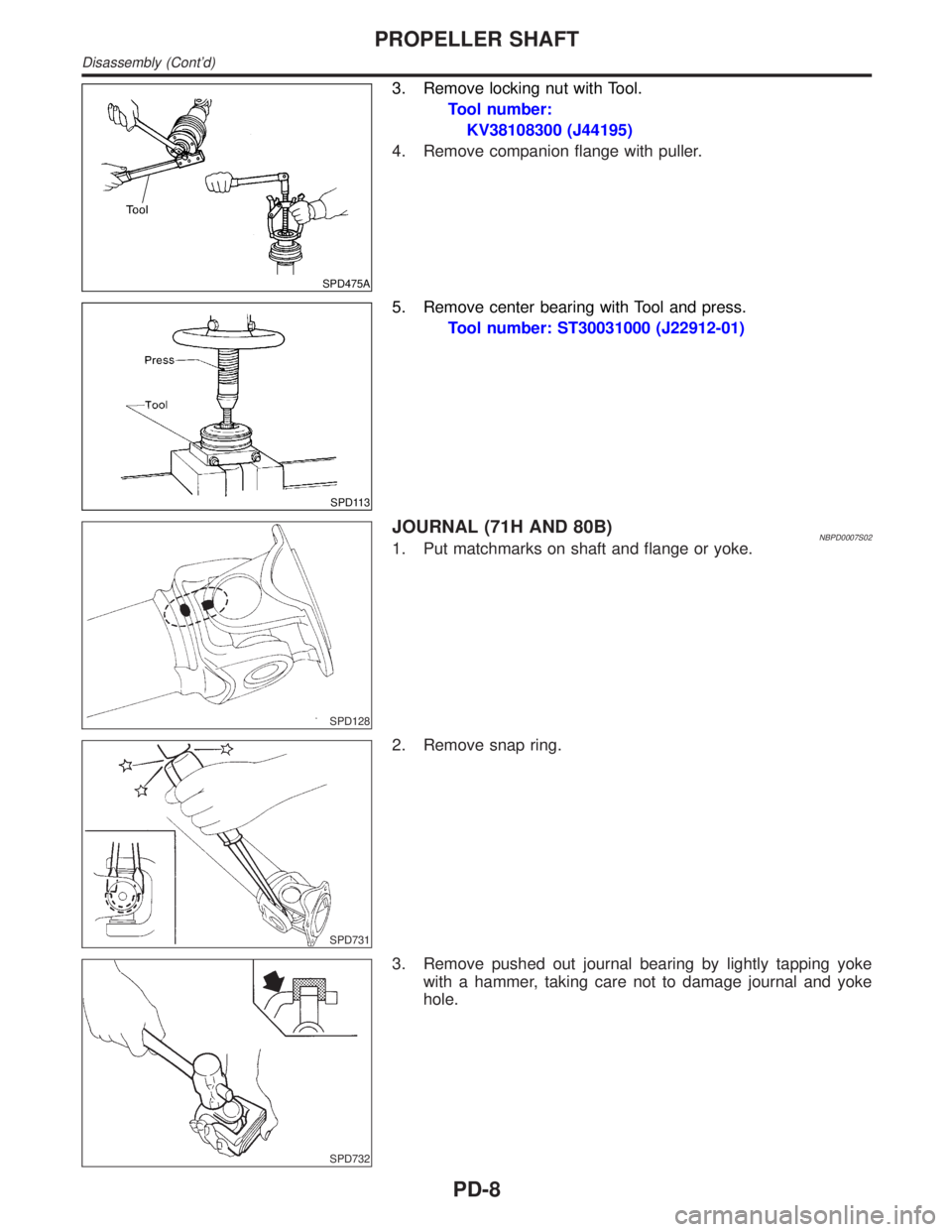
SPD475A
3. Remove locking nut with Tool.
Tool number:
KV38108300 (J44195)
4. Remove companion flange with puller.
SPD113
5. Remove center bearing with Tool and press.
Tool number: ST30031000 (J22912-01)
SPD128
JOURNAL (71H AND 80B)NBPD0007S021. Put matchmarks on shaft and flange or yoke.
SPD731
2. Remove snap ring.
SPD732
3. Remove pushed out journal bearing by lightly tapping yoke
with a hammer, taking care not to damage journal and yoke
hole.
PROPELLER SHAFT
Disassembly (Cont'd)
PD-8
Page 2038 of 2395
Preparation
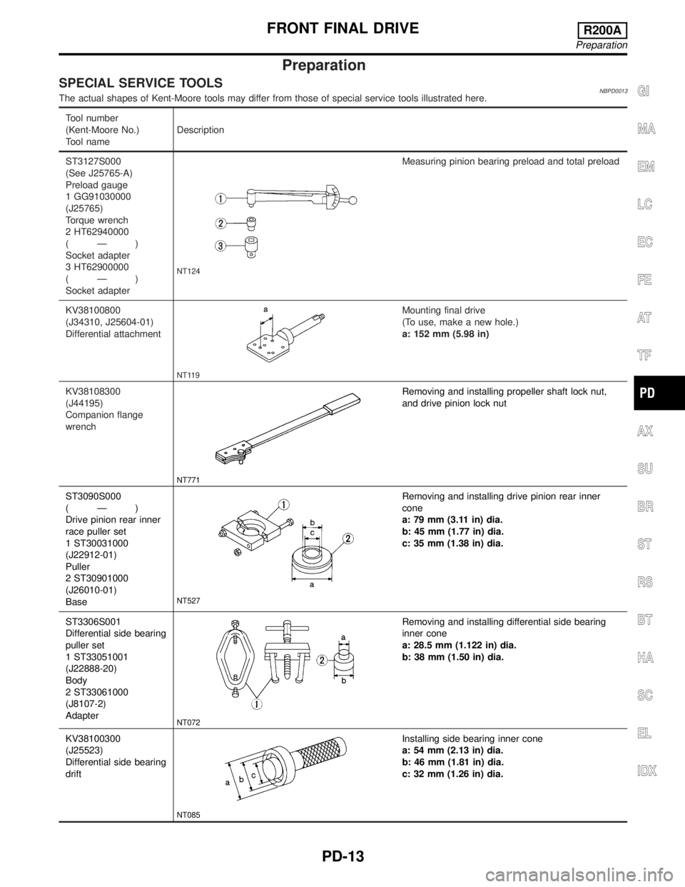
SPECIAL SERVICE TOOLSNBPD0013The actual shapes of Kent-Moore tools may differ from those of special service tools illustrated here.
Tool number
(Kent-Moore No.)
Tool nameDescription
ST3127S000
(See J25765-A)
Preload gauge
1 GG91030000
(J25765)
Torque wrench
2 HT62940000
(Ð)
Socket adapter
3 HT62900000
(Ð)
Socket adapter
NT124
Measuring pinion bearing preload and total preload
KV38100800
(J34310, J25604-01)
Differential attachment
NT119
Mounting final drive
(To use, make a new hole.)
a: 152 mm (5.98 in)
KV38108300
(J44195)
Companion flange
wrench
NT771
Removing and installing propeller shaft lock nut,
and drive pinion lock nut
ST3090S000
(Ð)
Drive pinion rear inner
race puller set
1 ST30031000
(J22912-01)
Puller
2 ST30901000
(J26010-01)
Base
NT527
Removing and installing drive pinion rear inner
cone
a: 79 mm (3.11 in) dia.
b: 45 mm (1.77 in) dia.
c: 35 mm (1.38 in) dia.
ST3306S001
Differential side bearing
puller set
1 ST33051001
(J22888-20)
Body
2 ST33061000
(J8107-2)
Adapter
NT072
Removing and installing differential side bearing
inner cone
a: 28.5 mm (1.122 in) dia.
b: 38 mm (1.50 in) dia.
KV38100300
(J25523)
Differential side bearing
drift
NT085
Installing side bearing inner cone
a: 54 mm (2.13 in) dia.
b: 46 mm (1.81 in) dia.
c: 32 mm (1.26 in) dia.
GI
MA
EM
LC
EC
FE
AT
TF
AX
SU
BR
ST
RS
BT
HA
SC
EL
IDX
FRONT FINAL DRIVER200A
Preparation
PD-13