Page 2194 of 2395
Disassembly and AssemblyNBST0018
SST845C
1. Combination switch
2. Lock nut
3. Jacket tube assembly4. Tilt lever
5. Tilt spring
6. Steering column shaft assembly7. Band
8. Jacket tube bracket insulator
assembly
9. Hole cover
SST490C
IWhen disassembling and assembling, unlock steering lock
with key.
IInstall lock nut on steering column shaft and tighten the nut to
specification.
: 25 - 34 N´m (2.5 - 3.5 kg-m, 18 - 25 ft-lb)
SST742A
ISteering lock
a) Break self-shear type screws with a drill or other appropriate
tool.
b) Install new self-shear type screws and then cut off self-shear
type screw heads.
GI
MA
EM
LC
EC
FE
AT
TF
PD
AX
SU
BR
RS
BT
HA
SC
EL
IDX
STEERING WHEEL AND STEERING COLUMN
Disassembly and Assembly
ST-13
Page 2198 of 2395
ComponentsNBST0026
SST618CB
1. Rear cover cap
2. Rear housing assembly
3. Pinion seal ring
4. Pinion assembly
5. O-ring
6. Shim
7. Pinion oil seal
8. Lock nut
9. Adjusting screw
10. Spring11. Retainer
12. Gear housing assembly
13. Rack oil seal
14. Rack assembly
15. Rack seal ring
16. O-ring
17. O-ring
18. Rack bushing
19. Rack oil seal
20. Snap ring21. End cover assembly
22. Boot clamp
23. Dust boot
24. Boot clamp
25. Lock plate
26. Tie-rod inner socket
27. Tie-rod
28. Tie-rod outer socket
29. Cotter pin
30. Cylinder tube
GI
MA
EM
LC
EC
FE
AT
TF
PD
AX
SU
BR
RS
BT
HA
SC
EL
IDX
POWER STEERING GEAR AND LINKAGE
Components
ST-17
Page 2205 of 2395
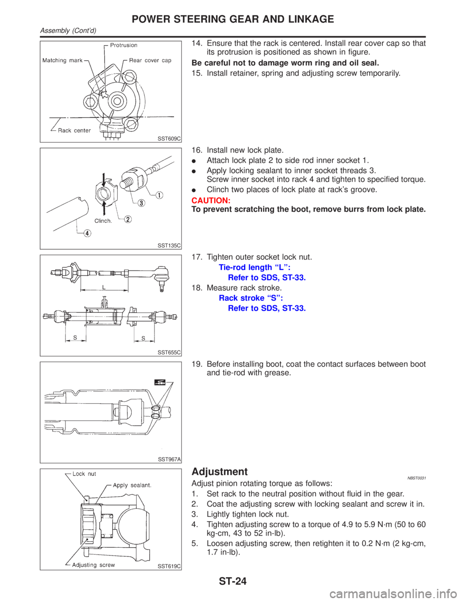
SST609C
14. Ensure that the rack is centered. Install rear cover cap so that
its protrusion is positioned as shown in figure.
Be careful not to damage worm ring and oil seal.
15. Install retainer, spring and adjusting screw temporarily.
SST135C
16. Install new lock plate.
IAttach lock plate 2 to side rod inner socket 1.
IApply locking sealant to inner socket threads 3.
Screw inner socket into rack 4 and tighten to specified torque.
IClinch two places of lock plate at rack's groove.
CAUTION:
To prevent scratching the boot, remove burrs from lock plate.
SST655C
17. Tighten outer socket lock nut.
Tie-rod length ªLº:
Refer to SDS, ST-33.
18. Measure rack stroke.
Rack stroke ªSº:
Refer to SDS, ST-33.
SST967A
19. Before installing boot, coat the contact surfaces between boot
and tie-rod with grease.
SST619C
AdjustmentNBST0031Adjust pinion rotating torque as follows:
1. Set rack to the neutral position without fluid in the gear.
2. Coat the adjusting screw with locking sealant and screw it in.
3. Lightly tighten lock nut.
4. Tighten adjusting screw to a torque of 4.9 to 5.9 N´m (50 to 60
kg-cm, 43 to 52 in-lb).
5. Loosen adjusting screw, then retighten it to 0.2 N´m (2 kg-cm,
1.7 in-lb).
POWER STEERING GEAR AND LINKAGE
Assembly (Cont'd)
ST-24
Page 2206 of 2395
SST718CA
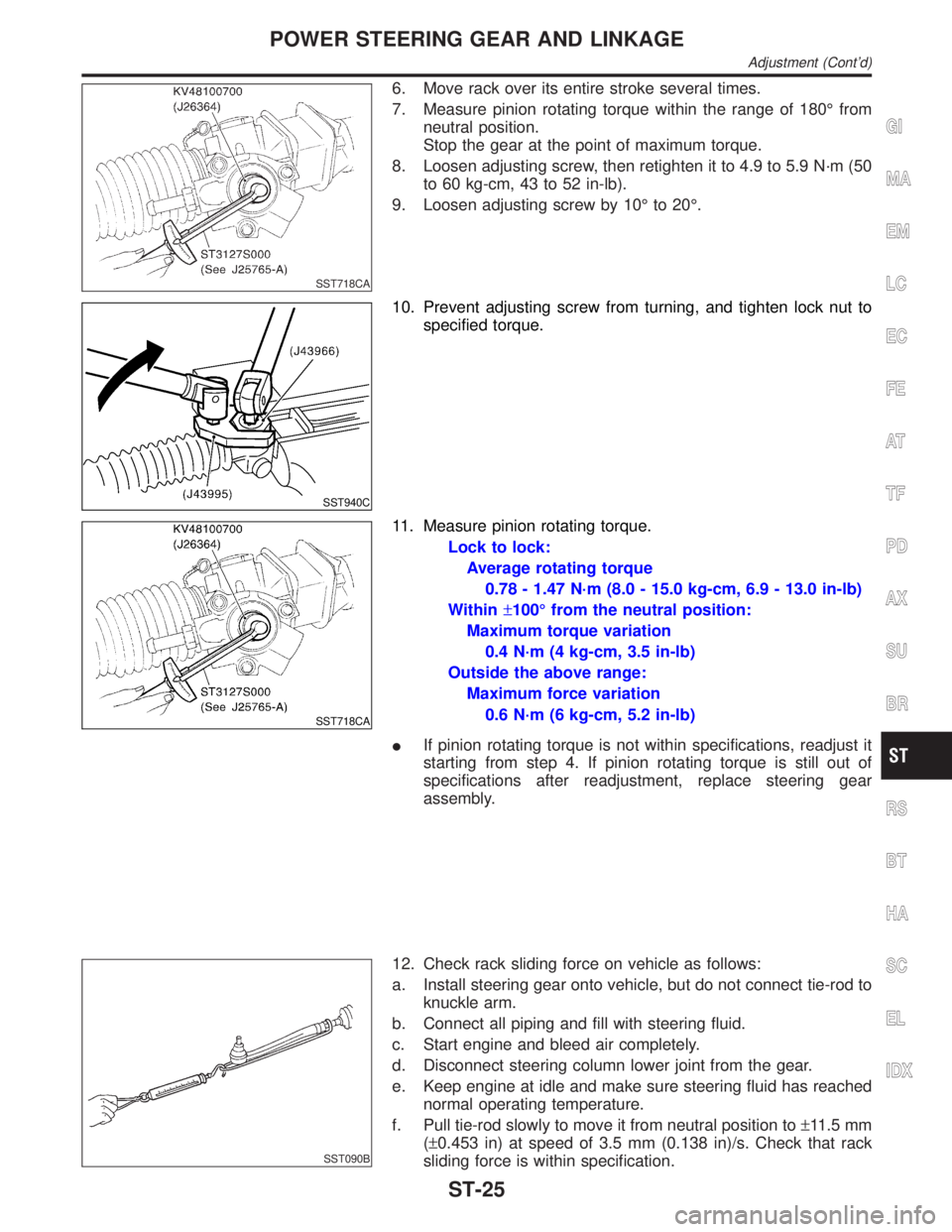
6. Move rack over its entire stroke several times.
7. Measure pinion rotating torque within the range of 180É from
neutral position.
Stop the gear at the point of maximum torque.
8. Loosen adjusting screw, then retighten it to 4.9 to 5.9 N´m (50
to 60 kg-cm, 43 to 52 in-lb).
9. Loosen adjusting screw by 10É to 20É.
SST940C
10. Prevent adjusting screw from turning, and tighten lock nut to
specified torque.
SST718CA
11. Measure pinion rotating torque.
Lock to lock:
Average rotating torque
0.78 - 1.47 N´m (8.0 - 15.0 kg-cm, 6.9 - 13.0 in-lb)
Within±100É from the neutral position:
Maximum torque variation
0.4 N´m (4 kg-cm, 3.5 in-lb)
Outside the above range:
Maximum force variation
0.6 N´m (6 kg-cm, 5.2 in-lb)
IIf pinion rotating torque is not within specifications, readjust it
starting from step 4. If pinion rotating torque is still out of
specifications after readjustment, replace steering gear
assembly.
SST090B
12. Check rack sliding force on vehicle as follows:
a. Install steering gear onto vehicle, but do not connect tie-rod to
knuckle arm.
b. Connect all piping and fill with steering fluid.
c. Start engine and bleed air completely.
d. Disconnect steering column lower joint from the gear.
e. Keep engine at idle and make sure steering fluid has reached
normal operating temperature.
f. Pull tie-rod slowly to move it from neutral position to±11.5 mm
(±0.453 in) at speed of 3.5 mm (0.138 in)/s. Check that rack
sliding force is within specification.
GI
MA
EM
LC
EC
FE
AT
TF
PD
AX
SU
BR
RS
BT
HA
SC
EL
IDX
POWER STEERING GEAR AND LINKAGE
Adjustment (Cont'd)
ST-25
Page 2213 of 2395
General SpecificationsNBST0037
Applied modelAll
Steering modelPower steering
Steering gear typePR32K
Steering overall gear ratio 17.2
Turns of steering wheel
(Lock to lock)3.09
Steering column type Collapsible, tilt
Steering WheelNBST0038Unit: mm (in)
Steering wheel axial play0 (0)
Steering wheel play35 (1.38) or less
Movement of gear housing±2(±0.08) or less
Steering ColumnNBST0039Unit: mm (in)
Steering column length ªL1º 716.7 - 718.7 (28.22 - 28.30)
Steering column lower shaft length ªL
2º 178 - 180 (7.01 - 7.09)
Steering column upper joint length ªL
3º 430.7 - 432.7 (16.96 - 17.04)
SST739C
Steering Transfer GearNBST0041
Rotating torque0.25 - 0.69 N´m (2.5 - 7.0 kg-cm, 2.2 - 6.1 in-lb)
SERVICE DATA AND SPECIFICATIONS (SDS)
General Specifications
ST-32
Page 2214 of 2395
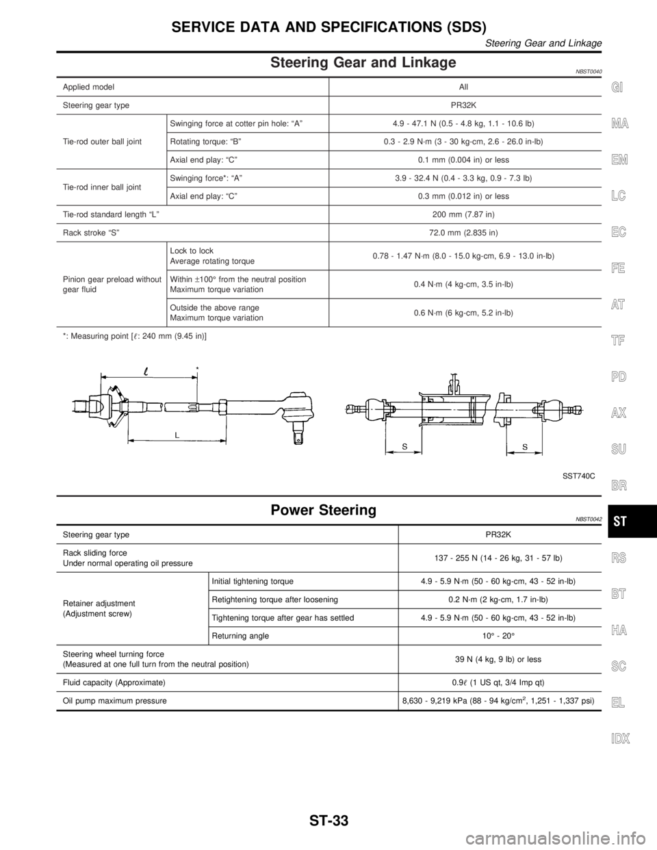
Steering Gear and LinkageNBST0040
Applied modelAll
Steering gear typePR32K
Tie-rod outer ball jointSwinging force at cotter pin hole: ªAº 4.9 - 47.1 N (0.5 - 4.8 kg, 1.1 - 10.6 lb)
Rotating torque: ªBº 0.3 - 2.9 N´m (3 - 30 kg-cm, 2.6 - 26.0 in-lb)
Axial end play: ªCº 0.1 mm (0.004 in) or less
Tie-rod inner ball jointSwinging force*: ªAº 3.9 - 32.4 N (0.4 - 3.3 kg, 0.9 - 7.3 lb)
Axial end play: ªCº 0.3 mm (0.012 in) or less
Tie-rod standard length ªLº200 mm (7.87 in)
Rack stroke ªSº72.0 mm (2.835 in)
Pinion gear preload without
gear fluidLock to lock
Average rotating torque0.78 - 1.47 N´m (8.0 - 15.0 kg-cm, 6.9 - 13.0 in-lb)
Within±100É from the neutral position
Maximum torque variation0.4 N´m (4 kg-cm, 3.5 in-lb)
Outside the above range
Maximum torque variation0.6 N´m (6 kg-cm, 5.2 in-lb)
*: Measuring point [: 240 mm (9.45 in)]
SST740C
Power SteeringNBST0042
Steering gear typePR32K
Rack sliding force
Under normal operating oil pressure137 - 255 N (14 - 26 kg, 31 - 57 lb)
Retainer adjustment
(Adjustment screw)Initial tightening torque 4.9 - 5.9 N´m (50 - 60 kg-cm, 43 - 52 in-lb)
Retightening torque after loosening 0.2 N´m (2 kg-cm, 1.7 in-lb)
Tightening torque after gear has settled 4.9 - 5.9 N´m (50 - 60 kg-cm, 43 - 52 in-lb)
Returning angle 10É - 20É
Steering wheel turning force
(Measured at one full turn from the neutral position)39 N (4 kg, 9 lb) or less
Fluid capacity (Approximate)0.9(1 US qt, 3/4 Imp qt)
Oil pump maximum pressure 8,630 - 9,219 kPa (88 - 94 kg/cm
2, 1,251 - 1,337 psi)
GI
MA
EM
LC
EC
FE
AT
TF
PD
AX
SU
BR
RS
BT
HA
SC
EL
IDX
SERVICE DATA AND SPECIFICATIONS (SDS)
Steering Gear and Linkage
ST-33
Page 2222 of 2395
SFA614B
SFA234AC
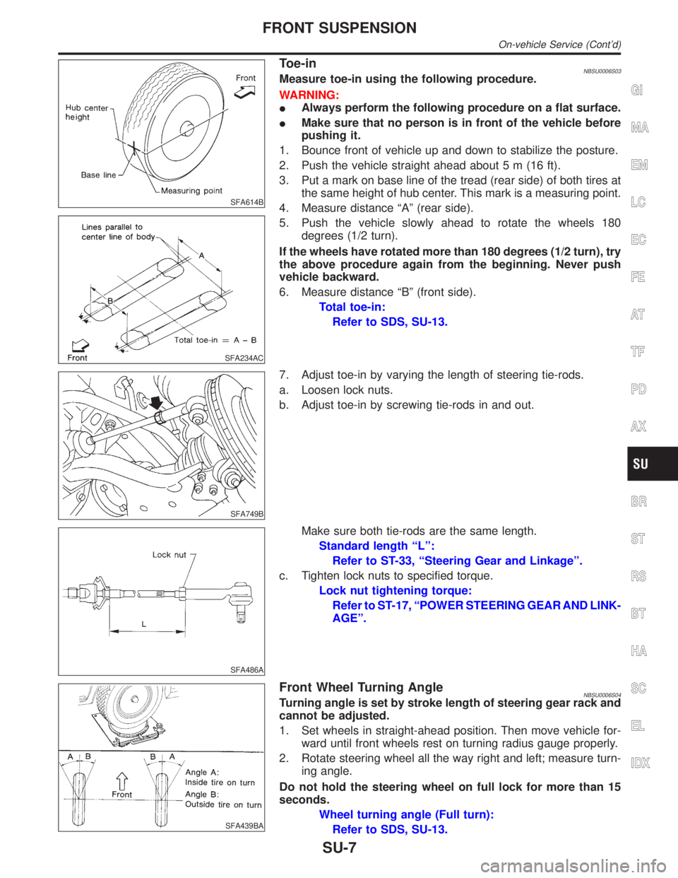
Toe-inNBSU0006S03Measure toe-in using the following procedure.
WARNING:
IAlways perform the following procedure on a flat surface.
IMake sure that no person is in front of the vehicle before
pushing it.
1. Bounce front of vehicle up and down to stabilize the posture.
2. Push the vehicle straight ahead about 5 m (16 ft).
3. Put a mark on base line of the tread (rear side) of both tires at
the same height of hub center. This mark is a measuring point.
4. Measure distance ªAº (rear side).
5. Push the vehicle slowly ahead to rotate the wheels 180
degrees (1/2 turn).
If the wheels have rotated more than 180 degrees (1/2 turn), try
the above procedure again from the beginning. Never push
vehicle backward.
6. Measure distance ªBº (front side).
Total toe-in:
Refer to SDS, SU-13.
SFA749B
7. Adjust toe-in by varying the length of steering tie-rods.
a. Loosen lock nuts.
b. Adjust toe-in by screwing tie-rods in and out.
SFA486A
Make sure both tie-rods are the same length.
Standard length ªLº:
Refer to ST-33, ªSteering Gear and Linkageº.
c. Tighten lock nuts to specified torque.
Lock nut tightening torque:
Refer to ST-17, ªPOWER STEERING GEAR AND LINK-
AGEº.
SFA439BA
Front Wheel Turning AngleNBSU0006S04Turning angle is set by stroke length of steering gear rack and
cannot be adjusted.
1. Set wheels in straight-ahead position. Then move vehicle for-
ward until front wheels rest on turning radius gauge properly.
2. Rotate steering wheel all the way right and left; measure turn-
ing angle.
Do not hold the steering wheel on full lock for more than 15
seconds.
Wheel turning angle (Full turn):
Refer to SDS, SU-13.
GI
MA
EM
LC
EC
FE
AT
TF
PD
AX
BR
ST
RS
BT
HA
SC
EL
IDX
FRONT SUSPENSION
On-vehicle Service (Cont'd)
SU-7
Page 2224 of 2395
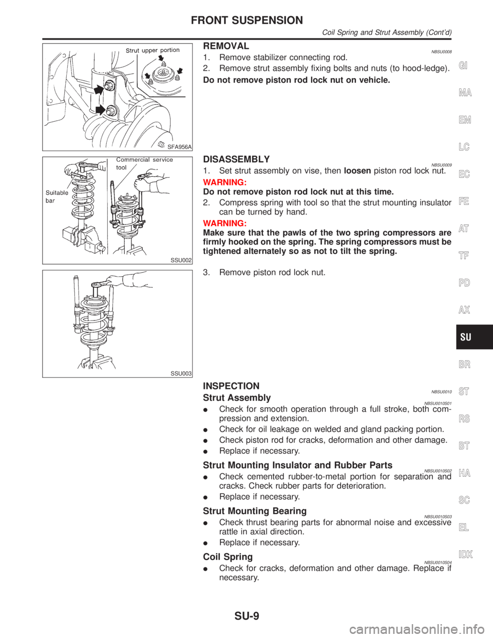
SFA956A
REMOVALNBSU00081. Remove stabilizer connecting rod.
2. Remove strut assembly fixing bolts and nuts (to hood-ledge).
Do not remove piston rod lock nut on vehicle.
SSU002
DISASSEMBLYNBSU00091. Set strut assembly on vise, thenloosenpiston rod lock nut.
WARNING:
Do not remove piston rod lock nut at this time.
2. Compress spring with tool so that the strut mounting insulator
can be turned by hand.
WARNING:
Make sure that the pawls of the two spring compressors are
firmly hooked on the spring. The spring compressors must be
tightened alternately so as not to tilt the spring.
SSU003
3. Remove piston rod lock nut.
INSPECTIONNBSU0010Strut AssemblyNBSU0010S01ICheck for smooth operation through a full stroke, both com-
pression and extension.
ICheck for oil leakage on welded and gland packing portion.
ICheck piston rod for cracks, deformation and other damage.
IReplace if necessary.
Strut Mounting Insulator and Rubber PartsNBSU0010S02ICheck cemented rubber-to-metal portion for separation and
cracks. Check rubber parts for deterioration.
IReplace if necessary.
Strut Mounting BearingNBSU0010S03ICheck thrust bearing parts for abnormal noise and excessive
rattle in axial direction.
IReplace if necessary.
Coil SpringNBSU0010S04ICheck for cracks, deformation and other damage. Replace if
necessary.
GI
MA
EM
LC
EC
FE
AT
TF
PD
AX
BR
ST
RS
BT
HA
SC
EL
IDX
FRONT SUSPENSION
Coil Spring and Strut Assembly (Cont'd)
SU-9