Page 1106 of 2395

16 CHECK THROTTLE POSITION SWITCH
1. Install all removed parts.
2. Start engine and warm it up to normal operating temperature.
3. Turn ignition switch ªOFFº.
4. Remove vacuum hose connected to throttle opener.
5. Connect suitable vacuum hose to vacuum pump and the throttle opener.
6. Apply vacuum [more than þ40.0 kPa (þ300 mmHg, þ11.81 inHg)] until the throttle drum becomes free from the rod of
the throttle opener.
SEF793W
7. Disconnect closed throttle position switch harness connector.
8. Check continuity between closed throttle position switch terminals 6 and 5 under the following conditions.
Resistance measurement must be made with throttle position switch installed in vehicle.
SEF998Y
OK or NG
OK©GO TO 18.
NG©GO TO 17.
17 ADJUST THROTTLE POSITION SWITCH
Check the following items. Refer to ªBasic Inspectionº, EC-101.
MTBL0470
Is it possible to adjust closed throttle position switch?
YesorNo
Ye s©GO TO 18.
No©Replace throttle position switch.
GI
MA
EM
LC
FE
AT
TF
PD
AX
SU
BR
ST
RS
BT
HA
SC
EL
IDX
DTC P1447 EVAPORATIVE EMISSION (EVAP) CONTROL SYSTEM PURGE
FLOW MONITORING
Diagnostic Procedure (Cont'd)
EC-571
Page 1140 of 2395

DTC Confirmation ProcedureNBEC0371CAUTION:
Always drive vehicle at a safe speed.
NOTE:
If ªDTC Confirmation Procedureº has been previously conducted,
always turn ignition switch ªOFFº and wait at least 10 seconds
before conducting the next test.
SEF212Y
SEF213Y
WITH CONSULT-IINBEC0371S011) Turn ignition switch ªONº.
2) Select ªP/N POSI SWº in ªDATA MONITORº mode with CON-
SULT-II. Then check the ªP/N POSI SWº signal under the fol-
lowing conditions.
Position (Selector lever) Known-good signal
ªNº and ªPº position ON
Except the above position OFF
If NG, go to ªDiagnostic Procedureº, EC-608.
If OK, go to following step.
3) Select ªDATA MONITORº mode with CONSULT-II.
4) Start engine and warm it up to normal operating temperature.
5) Maintain the following conditions for at least 60 consecutive
seconds.
ENG SPEED 1,500 - 2,500 rpm
COOLAN TEMP/S More than 70ÉC (158ÉF)
B/FUEL SCHDL 3.6 - 12 msec
VHCL SPEED SE 70 - 100 km/h (43 - 62 MPH)
Selector lever Suitable position
6) If 1st trip DTC is detected, go to ªDiagnostic Procedureº,
EC-608.
GI
MA
EM
LC
FE
AT
TF
PD
AX
SU
BR
ST
RS
BT
HA
SC
EL
IDX
DTC P1706 PARK/NEUTRAL POSITION (PNP) SWITCH
DTC Confirmation Procedure
EC-605
Page 1143 of 2395

Diagnostic ProcedureNBEC0374
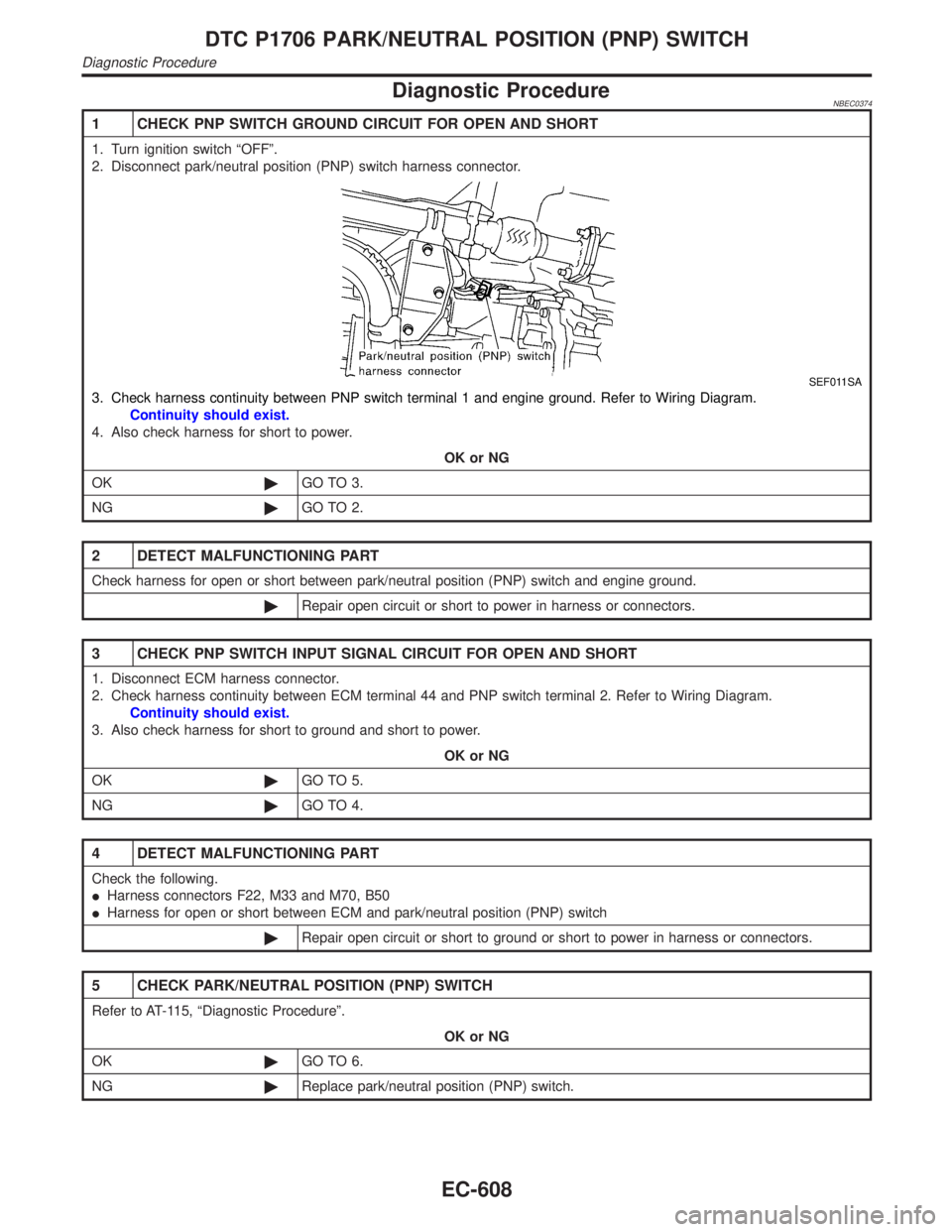
1 CHECK PNP SWITCH GROUND CIRCUIT FOR OPEN AND SHORT
1. Turn ignition switch ªOFFº.
2. Disconnect park/neutral position (PNP) switch harness connector.
SEF011SA
3. Check harness continuity between PNP switch terminal 1 and engine ground. Refer to Wiring Diagram.
Continuity should exist.
4. Also check harness for short to power.
OK or NG
OK©GO TO 3.
NG©GO TO 2.
2 DETECT MALFUNCTIONING PART
Check harness for open or short between park/neutral position (PNP) switch and engine ground.
©Repair open circuit or short to power in harness or connectors.
3 CHECK PNP SWITCH INPUT SIGNAL CIRCUIT FOR OPEN AND SHORT
1. Disconnect ECM harness connector.
2. Check harness continuity between ECM terminal 44 and PNP switch terminal 2. Refer to Wiring Diagram.
Continuity should exist.
3. Also check harness for short to ground and short to power.
OK or NG
OK©GO TO 5.
NG©GO TO 4.
4 DETECT MALFUNCTIONING PART
Check the following.
IHarness connectors F22, M33 and M70, B50
IHarness for open or short between ECM and park/neutral position (PNP) switch
©Repair open circuit or short to ground or short to power in harness or connectors.
5 CHECK PARK/NEUTRAL POSITION (PNP) SWITCH
Refer to AT-115, ªDiagnostic Procedureº.
OK or NG
OK©GO TO 6.
NG©Replace park/neutral position (PNP) switch.
DTC P1706 PARK/NEUTRAL POSITION (PNP) SWITCH
Diagnostic Procedure
EC-608
Page 1148 of 2395
Diagnostic ProcedureNBEC0598
1 CHECK OVERALL FUNCTION
With CONSULT-II
1. Start engine and warm it up to normal operating temperature.
2. Perform ªVIAS SOL VALVEº in ªACTIVE TESTº mode with CONSULT-II.
3. Turn VIAS control solenoid valve ªONº and ªOFFº, and make sure that power valve actuator rod moves.
SEC304C
Without CONSULT-II
1. Start engine and warm it up to normal operating temperature.
2. Rev engine quickly up to above 5,000 rpm and make sure that power valve actuator rod moves.
SEF021Z
OK or NG
OK©INSPECTION END
NG©GO TO 2.
GI
MA
EM
LC
FE
AT
TF
PD
AX
SU
BR
ST
RS
BT
HA
SC
EL
IDX
VARIABLE INDUCTION AIR CONTROL SYSTEM (VIAS)
Diagnostic Procedure
EC-613
Page 1149 of 2395

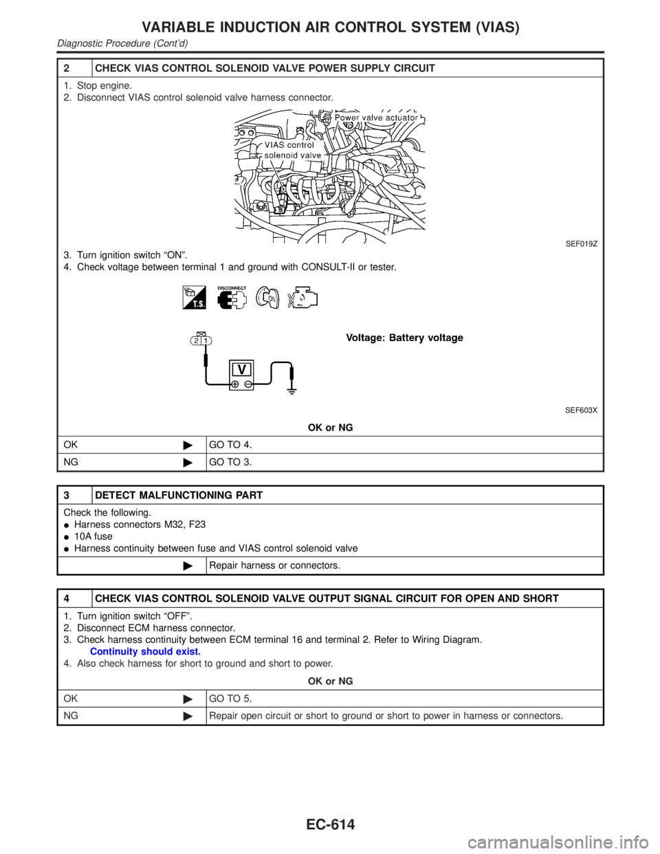
2 CHECK VIAS CONTROL SOLENOID VALVE POWER SUPPLY CIRCUIT
1. Stop engine.
2. Disconnect VIAS control solenoid valve harness connector.
SEF019Z
3. Turn ignition switch ªONº.
4. Check voltage between terminal 1 and ground with CONSULT-II or tester.
SEF603X
OK or NG
OK©GO TO 4.
NG©GO TO 3.
3 DETECT MALFUNCTIONING PART
Check the following.
IHarness connectors M32, F23
I10A fuse
IHarness continuity between fuse and VIAS control solenoid valve
©Repair harness or connectors.
4 CHECK VIAS CONTROL SOLENOID VALVE OUTPUT SIGNAL CIRCUIT FOR OPEN AND SHORT
1. Turn ignition switch ªOFFº.
2. Disconnect ECM harness connector.
3. Check harness continuity between ECM terminal 16 and terminal 2. Refer to Wiring Diagram.
Continuity should exist.
4. Also check harness for short to ground and short to power.
OK or NG
OK©GO TO 5.
NG©Repair open circuit or short to ground or short to power in harness or connectors.
VARIABLE INDUCTION AIR CONTROL SYSTEM (VIAS)
Diagnostic Procedure (Cont'd)
EC-614
Page 1153 of 2395
Diagnostic ProcedureNBEC0387
1 INSPECTION START
Turn ignition switch to ªSTARTº.
Is any cylinder ignited?
YesorNo
Ye s©GO TO 2.
No©GO TO 3.
2 CHECK OVERALL FUNCTION
With CONSULT-II
1. Start engine.
2. Perform ªPOWER BALANCEº in ªACTIVE TESTº mode with CONSULT-II.
SEF190Y
3. Make sure that each circuit produces a momentary engine speed drop.
Without CONSULT-II
1. Start engine.
2. Listen to each injector operating sound.
MEC703B
Clicking noise should be heard.
OK or NG
OK©INSPECTION END
NG©GO TO 3.
INJECTOR
Diagnostic Procedure
EC-618
Page 1171 of 2395
Diagnostic ProcedureNBEC0402
1 INSPECTION START
Do you have CONSULT-II?
YesorNo
Ye s©GO TO 2.
No©GO TO 3.
2 CHECK OVERALL FUNCTION
With CONSULT-II
1. Start engine.
2. Check ªPW/ST SIGNALº in ªDATA MONITORº mode with CONSULT-II under the following conditions.
SEF228Y
OK or NG
OK©INSPECTION END
NG©GO TO 4.
3 CHECK OVERALL FUNCTION
Without CONSULT-II
1. Start engine.
2. Check voltage between ECM terminal 47 and ground under the following conditions.
SEF363X
OK or NG
OK©INSPECTION END
NG©GO TO 4.
POWER STEERING OIL PRESSURE SWITCH
Diagnostic Procedure
EC-636
Page 1172 of 2395

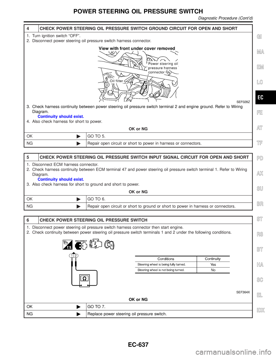
4 CHECK POWER STEERING OIL PRESSURE SWITCH GROUND CIRCUIT FOR OPEN AND SHORT
1. Turn ignition switch ªOFFº.
2. Disconnect power steering oil pressure switch harness connector.
SEF028Z
3. Check harness continuity between power steering oil pressure switch terminal 2 and engine ground. Refer to Wiring
Diagram.
Continuity should exist.
4. Also check harness for short to power.
OK or NG
OK©GO TO 5.
NG©Repair open circuit or short to power in harness or connectors.
5 CHECK POWER STEERING OIL PRESSURE SWITCH INPUT SIGNAL CIRCUIT FOR OPEN AND SHORT
1. Disconnect ECM harness connector.
2. Check harness continuity between ECM terminal 47 and power steering oil pressure switch terminal 1. Refer to Wiring
Diagram.
Continuity should exist.
3. Also check harness for short to ground and short to power.
OK or NG
OK©GO TO 6.
NG©Repair open circuit or short to ground or short to power in harness or connectors.
6 CHECK POWER STEERING OIL PRESSURE SWITCH
1. Disconnect power steering oil pressure switch harness connector then start engine.
2. Check continuity between power steering oil pressure switch terminals 1 and 2 under the following conditions.
SEF364X
OK or NG
OK©GO TO 7.
NG©Replace power steering oil pressure switch.
GI
MA
EM
LC
FE
AT
TF
PD
AX
SU
BR
ST
RS
BT
HA
SC
EL
IDX
POWER STEERING OIL PRESSURE SWITCH
Diagnostic Procedure (Cont'd)
EC-637