Page 1176 of 2395
Diagnostic ProcedureNBEC0638
1 CHECK REFRIGERANT PRESSURE SENSOR OVERALL FUNCTION
1. Start engine and warm it up to normal operating temperature.
2. Turn A/C switch and blower switch ªONº.
3. Check voltage between ECM terminal 81 and ground with CONSULT-II or tester.
SEF617XA
OK or NG
OK©INSPECTION END
NG©GO TO 2.
2 CHECK REFRIGERANT PRESSURE SENSOR POWER SUPPLY CIRCUIT
1. Turn A/C switch and blower switch ªOFFº.
2. Stop engine.
3. Disconnect refrigerant pressure sensor harness connector.
SEF029Z
4. Turn ignition switch ªONº.
5. Check voltage between refrigerant pressure sensor terminal 1 and ground with CONSULT-II or tester.
SEF030Z
OK or NG
OK©GO TO 4.
NG©GO TO 3.
GI
MA
EM
LC
FE
AT
TF
PD
AX
SU
BR
ST
RS
BT
HA
SC
EL
IDX
REFRIGERANT PRESSURE SENSOR
Diagnostic Procedure
EC-641
Page 1177 of 2395

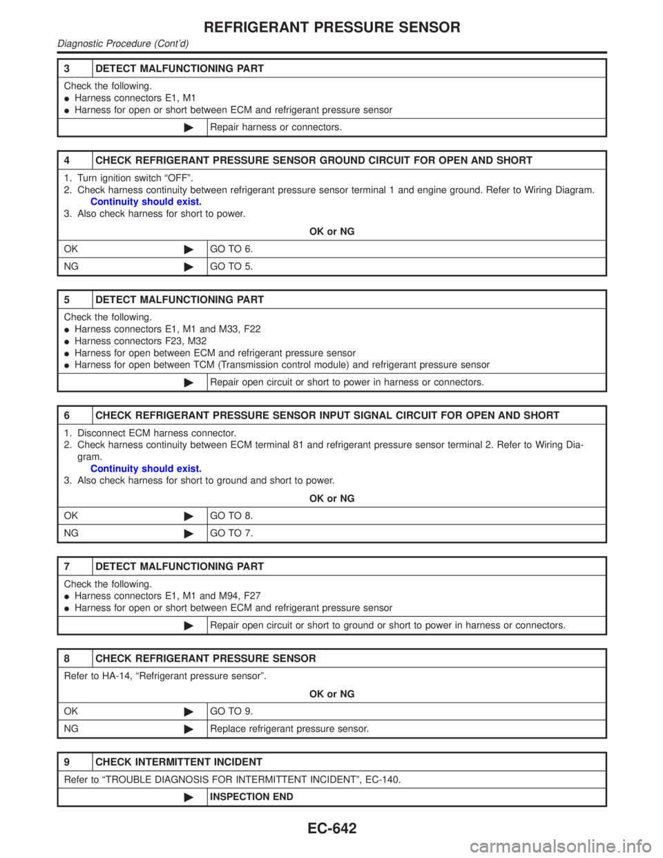
3 DETECT MALFUNCTIONING PART
Check the following.
IHarness connectors E1, M1
IHarness for open or short between ECM and refrigerant pressure sensor
©Repair harness or connectors.
4 CHECK REFRIGERANT PRESSURE SENSOR GROUND CIRCUIT FOR OPEN AND SHORT
1. Turn ignition switch ªOFFº.
2. Check harness continuity between refrigerant pressure sensor terminal 1 and engine ground. Refer to Wiring Diagram.
Continuity should exist.
3. Also check harness for short to power.
OK or NG
OK©GO TO 6.
NG©GO TO 5.
5 DETECT MALFUNCTIONING PART
Check the following.
IHarness connectors E1, M1 and M33, F22
IHarness connectors F23, M32
IHarness for open between ECM and refrigerant pressure sensor
IHarness for open between TCM (Transmission control module) and refrigerant pressure sensor
©Repair open circuit or short to power in harness or connectors.
6 CHECK REFRIGERANT PRESSURE SENSOR INPUT SIGNAL CIRCUIT FOR OPEN AND SHORT
1. Disconnect ECM harness connector.
2. Check harness continuity between ECM terminal 81 and refrigerant pressure sensor terminal 2. Refer to Wiring Dia-
gram.
Continuity should exist.
3. Also check harness for short to ground and short to power.
OK or NG
OK©GO TO 8.
NG©GO TO 7.
7 DETECT MALFUNCTIONING PART
Check the following.
IHarness connectors E1, M1 and M94, F27
IHarness for open or short between ECM and refrigerant pressure sensor
©Repair open circuit or short to ground or short to power in harness or connectors.
8 CHECK REFRIGERANT PRESSURE SENSOR
Refer to HA-14, ªRefrigerant pressure sensorº.
OK or NG
OK©GO TO 9.
NG©Replace refrigerant pressure sensor.
9 CHECK INTERMITTENT INCIDENT
Refer to ªTROUBLE DIAGNOSIS FOR INTERMITTENT INCIDENTº, EC-140.
©INSPECTION END
REFRIGERANT PRESSURE SENSOR
Diagnostic Procedure (Cont'd)
EC-642
Page 1180 of 2395
Diagnostic ProcedureNBEC0605
1 CHECK LOAD SIGNAL CIRCUIT OVERALL FUNCTION-I
1. Turn ignition switch ªONº.
2. Check voltage between ECM terminal 52 and ground under the following conditions.
SEF610X
OK or NG
OK©GO TO 2.
NG©GO TO 3.
2 CHECK LOAD SIGNAL CIRCUIT OVERALL FUNCTION-II
Check voltage between ECM terminal 52 and ground under the following conditions.
SEF611X
OK or NG
OK©INSPECTION END
NG©GO TO 7.
3 CHECK REAR WINDOW DEFOGGER FUNCTION
1. Start engine.
2. Turn ªONº the rear window defogger switch.
3. Check the rear windshield. Is the rear windshield heated up?
YesorNo
Ye s©GO TO 4.
No©Refer to EL-151, ªRear Window Defoggerº.
GI
MA
EM
LC
FE
AT
TF
PD
AX
SU
BR
ST
RS
BT
HA
SC
EL
IDX
ELECTRICAL LOAD SIGNAL
Diagnostic Procedure
EC-645
Page 1181 of 2395

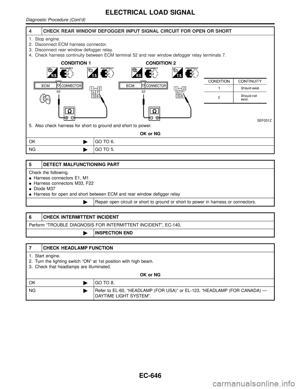
4 CHECK REAR WINDOW DEFOGGER INPUT SIGNAL CIRCUIT FOR OPEN OR SHORT
1. Stop engine.
2. Disconnect ECM harness connector.
3. Disconnect rear window defogger relay.
4. Check harness continuity between ECM terminal 52 and rear window defogger relay terminals 7.
SEF031Z
5. Also check harness for short to ground and short to power.
OK or NG
OK©GO TO 6.
NG©GO TO 5.
5 DETECT MALFUNCTIONING PART
Check the following.
IHarness connectors E1, M1
IHarness connectors M33, F22
IDiode M37
IHarness for open and short between ECM and rear window defigger relay
©Repair open circuit or short to ground or short to power in harness or connectors.
6 CHECK INTERMITTENT INCIDENT
Perform ªTROUBLE DIAGNOSIS FOR INTERMITTENT INCIDENTº, EC-140.
©INSPECTION END
7 CHECK HEADLAMP FUNCTION
1. Start engine.
2. Turn the lighting switch ªONº at 1st position with high beam.
3. Check that headlamps are illuminated.
OK or NG
OK©GO TO 8.
NG©Refer to EL-60, ªHEADLAMP (FOR USA)º or EL-123, ªHEADLAMP (FOR CANADA) Ð
DAYTIME LIGHT SYSTEMº.
ELECTRICAL LOAD SIGNAL
Diagnostic Procedure (Cont'd)
EC-646
Page 1182 of 2395
8 CHECK HEADLAMP INPUT SIGNAL CIRCUIT FOR OPEN OR SHORT
1. Stop engine.
2. Disconnect ECM harness connector.
3. Disconnect headlamp LH relay.
4. Check harness continuity between ECM terminal 52 and headlamp LH relay terminal 7 under the following conditions.
SEF031Z
5. Also check harness for short to ground and short to power.
OK or NG
OK©GO TO 10.
NG©GO TO 9.
9 DETECT MALFUNCTIONING PART
Check the following.
IHarness connectors E1, M1
IHarness connectors M33, F22
IDiode E121
IHarness for open and short between ECM and headlamp LH relay or daytime light control unit
©Repair open circuit or short to ground or short to power in harness or connectors.
10 CHECK INTERMITTENT INCIDENT
Perform ªTROUBLE DIAGNOSIS FOR INTERMITTENT INCIDENTº, EC-140.
©INSPECTION END
GI
MA
EM
LC
FE
AT
TF
PD
AX
SU
BR
ST
RS
BT
HA
SC
EL
IDX
ELECTRICAL LOAD SIGNAL
Diagnostic Procedure (Cont'd)
EC-647
Page 1287 of 2395

SYMPTOM CHARTNBEL0201S02Symptom Chart 1 (Malfunction is Indicated in
Diagnosis Mode)
NBEL0201S0201
Symptom Possible causes Repair order
Odo/trip meter indicate(s)
malfunction in Diagnosis
mode.Unified meter control unit Replace unified meter control unit.
Multiple meter/gauge indi-
cate malfunction in Diagno-
sis mode.
One of speedometer/
tachometer/fuel gauge/
water temp. gauge indi-
cates malfunction in Diag-
nosis mode.1. Meter/Gauge
2. Unified meter control unit1. Check resistance of meter/gauge indicating malfunc-
tion. If the resistance is NG, replace the meter/
gauge. Refer to ªMETER/GAUGE RESISTANCE
CHECKº, EL-108.
2. If the resistance of meter/gauge is OK, replace uni-
fied meter control unit.
Symptom Chart 2 (No Malfunction is Indicated in
Diagnosis Mode)
NBEL0201S0202
Symptom Possible causes Repair order
One of speedometer/
tachometer/fuel gauge/
water temp. gauge is mal-
functioning.1. Sensor signal
- Vehicle speed signal
- Engine revolution signal
- Fuel gauge
- Water temp. gauge
2. Unified meter control unit1. Check the sensor for malfunctioning meter/gauge.
INSPECTION/VEHICLE SPEED SENSOR (Refer to
EL-104.)
INSPECTION/ENGINE REVOLUTION SIGNAL
(Refer to EL-105.)
INSPECTION/FUEL LEVEL SENSOR UNIT (Refer to
EL-106.)
INSPECTION/THERMAL TRANSMITTER (Refer to
EL-107.)
2. Replace unified meter control unit. Multiple meter/gauge are
malfunctioning. (except
odo/trip meter)
Before starting trouble diagnoses below, perform PRELIMINARY
CHECK, EL-101.
METERS AND GAUGES
Trouble Diagnoses (Cont'd)
EL-102
Page 1290 of 2395
INSPECTION/ENGINE REVOLUTION SIGNALNBEL0201S05
1 CHECK ECM OUTPUT
1. Start engine.
2. Check voltage between combination meter terminals 16 and ground at idle and 2,000 rpm.
SEL364WB
OK or NG
OK©Engine revolution signal is OK.
NG©Harness for open or short between ECM and combination meter
GI
MA
EM
LC
EC
FE
AT
TF
PD
AX
SU
BR
ST
RS
BT
HA
SC
IDX
METERS AND GAUGES
Trouble Diagnoses (Cont'd)
EL-105
Page 1297 of 2395

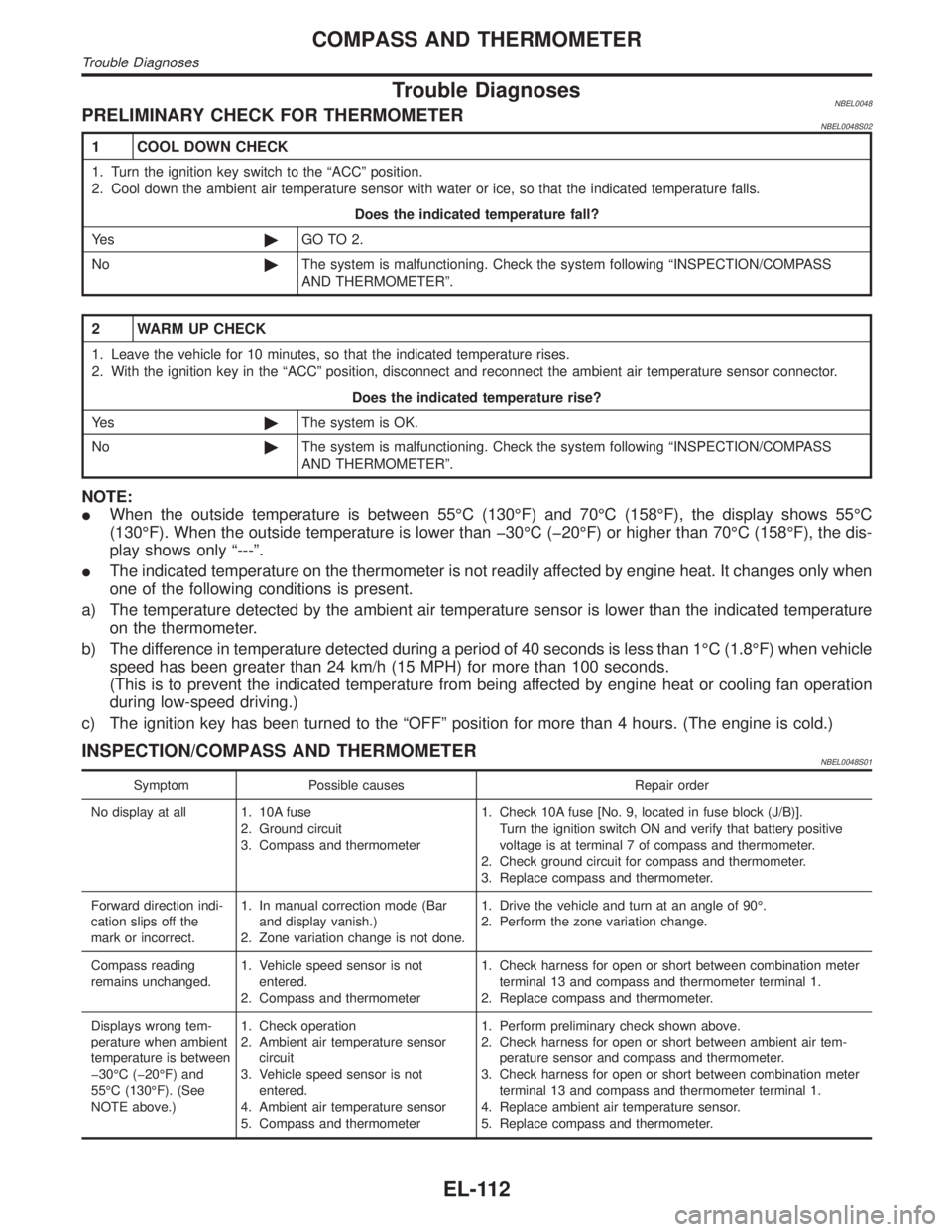
Trouble DiagnosesNBEL0048PRELIMINARY CHECK FOR THERMOMETERNBEL0048S02
1 COOL DOWN CHECK
1. Turn the ignition key switch to the ªACCº position.
2. Cool down the ambient air temperature sensor with water or ice, so that the indicated temperature falls.
Does the indicated temperature fall?
Ye s©GO TO 2.
No©The system is malfunctioning. Check the system following ªINSPECTION/COMPASS
AND THERMOMETERº.
2 WARM UP CHECK
1. Leave the vehicle for 10 minutes, so that the indicated temperature rises.
2. With the ignition key in the ªACCº position, disconnect and reconnect the ambient air temperature sensor connector.
Does the indicated temperature rise?
Ye s©The system is OK.
No©The system is malfunctioning. Check the system following ªINSPECTION/COMPASS
AND THERMOMETERº.
NOTE:
IWhen the outside temperature is between 55ÉC (130ÉF) and 70ÉC (158ÉF), the display shows 55ÉC
(130ÉF). When the outside temperature is lower than þ30ÉC (þ20ÉF) or higher than 70ÉC (158ÉF), the dis-
play shows only ª---º.
IThe indicated temperature on the thermometer is not readily affected by engine heat. It changes only when
one of the following conditions is present.
a) The temperature detected by the ambient air temperature sensor is lower than the indicated temperature
on the thermometer.
b) The difference in temperature detected during a period of 40 seconds is less than 1ÉC (1.8ÉF) when vehicle
speed has been greater than 24 km/h (15 MPH) for more than 100 seconds.
(This is to prevent the indicated temperature from being affected by engine heat or cooling fan operation
during low-speed driving.)
c) The ignition key has been turned to the ªOFFº position for more than 4 hours. (The engine is cold.)
INSPECTION/COMPASS AND THERMOMETERNBEL0048S01
Symptom Possible causes Repair order
No display at all 1. 10A fuse
2. Ground circuit
3. Compass and thermometer1. Check 10A fuse [No. 9, located in fuse block (J/B)].
Turn the ignition switch ON and verify that battery positive
voltage is at terminal 7 of compass and thermometer.
2. Check ground circuit for compass and thermometer.
3. Replace compass and thermometer.
Forward direction indi-
cation slips off the
mark or incorrect.1. In manual correction mode (Bar
and display vanish.)
2. Zone variation change is not done.1. Drive the vehicle and turn at an angle of 90É.
2. Perform the zone variation change.
Compass reading
remains unchanged.1. Vehicle speed sensor is not
entered.
2. Compass and thermometer1. Check harness for open or short between combination meter
terminal 13 and compass and thermometer terminal 1.
2. Replace compass and thermometer.
Displays wrong tem-
perature when ambient
temperature is between
þ30ÉC (þ20ÉF) and
55ÉC (130ÉF). (See
NOTE above.)1. Check operation
2. Ambient air temperature sensor
circuit
3. Vehicle speed sensor is not
entered.
4. Ambient air temperature sensor
5. Compass and thermometer1. Perform preliminary check shown above.
2. Check harness for open or short between ambient air tem-
perature sensor and compass and thermometer.
3. Check harness for open or short between combination meter
terminal 13 and compass and thermometer terminal 1.
4. Replace ambient air temperature sensor.
5. Replace compass and thermometer.
COMPASS AND THERMOMETER
Trouble Diagnoses
EL-112