2001 INFINITI QX4 check engine
[x] Cancel search: check enginePage 1307 of 2395

SEL062WA
Fuel Warning Lamp Sensor CheckNBEL01661. Turn ignition switch ªOFFº.
2. Disconnect fuel level sensor unit harness connector B12.
3. Connect a resistor (80W) between fuel tank gauge unit harness
connector terminals 2 and 3.
4. Turn ignition switch ªONº.
The fuel warning lamp should come on.
NOTE:
ECM might store the 1st trip DTC P0180 during this inspection.
If the DTC is stored in ECM memory, erase the DTC after recon-
necting fuel tank gauge unit harness connector.
Refer to EC-60, ªHOW TO ERASE EMISSION-RELATED DIAG-
NOSTIC INFORMATIONº.
MEL425F
Electrical Components InspectionNBEL0051OIL PRESSURE SWITCH CHECKNBEL0051S02
Oil pressure
kPa (kg/cm2, psi)Continuity
Engine startMore than 10 - 20
(0.1-0.2,1-3)NO
Engine stopLess than 10 - 20
(0.1-0.2,1-3)YES
Check the continuity between the terminals of oil pressure switch
and body ground.
SEL901F
DIODE CHECKNBEL0051S03ICheck continuity using an ohmmeter.
IDiode is functioning properly if test results are as shown in the
figure at left.
ICheck diodes at the combination meter harness connector
instead of checking them on the combination meter assembly.
Refer to EL-115, ªWARNING LAMPº wiring diagrams.
NOTE:
Specification may vary depending on the type of tester. Before
performing this inspection, be sure to refer to the instruction
manual for the tester to be used.
WARNING LAMPS
Fuel Warning Lamp Sensor Check
EL-122
Page 1351 of 2395
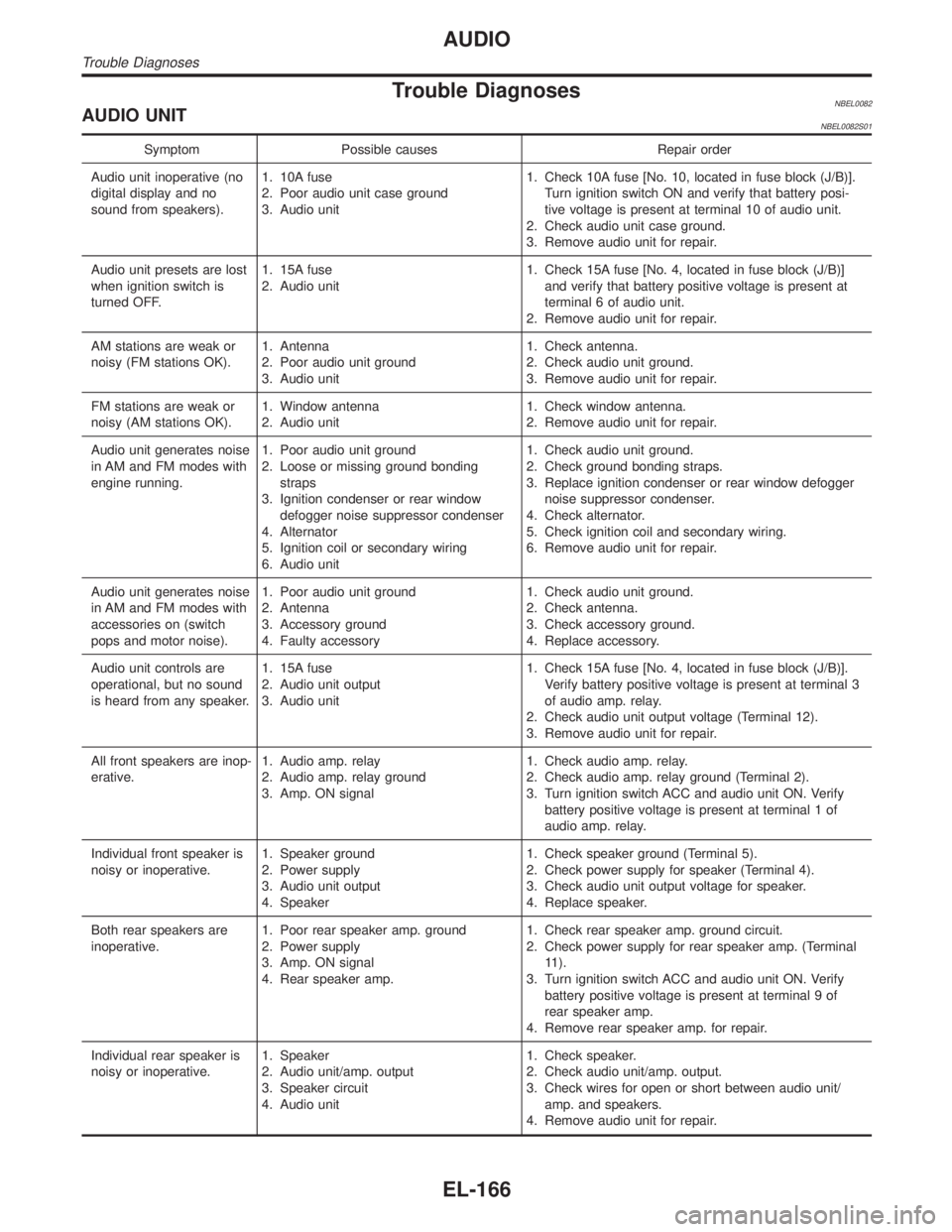
Trouble DiagnosesNBEL0082AUDIO UNITNBEL0082S01
Symptom Possible causes Repair order
Audio unit inoperative (no
digital display and no
sound from speakers).1. 10A fuse
2. Poor audio unit case ground
3. Audio unit1. Check 10A fuse [No. 10, located in fuse block (J/B)].
Turn ignition switch ON and verify that battery posi-
tive voltage is present at terminal 10 of audio unit.
2. Check audio unit case ground.
3. Remove audio unit for repair.
Audio unit presets are lost
when ignition switch is
turned OFF.1. 15A fuse
2. Audio unit1. Check 15A fuse [No. 4, located in fuse block (J/B)]
and verify that battery positive voltage is present at
terminal 6 of audio unit.
2. Remove audio unit for repair.
AM stations are weak or
noisy (FM stations OK).1. Antenna
2. Poor audio unit ground
3. Audio unit1. Check antenna.
2. Check audio unit ground.
3. Remove audio unit for repair.
FM stations are weak or
noisy (AM stations OK).1. Window antenna
2. Audio unit1. Check window antenna.
2. Remove audio unit for repair.
Audio unit generates noise
in AM and FM modes with
engine running.1. Poor audio unit ground
2. Loose or missing ground bonding
straps
3. Ignition condenser or rear window
defogger noise suppressor condenser
4. Alternator
5. Ignition coil or secondary wiring
6. Audio unit1. Check audio unit ground.
2. Check ground bonding straps.
3. Replace ignition condenser or rear window defogger
noise suppressor condenser.
4. Check alternator.
5. Check ignition coil and secondary wiring.
6. Remove audio unit for repair.
Audio unit generates noise
in AM and FM modes with
accessories on (switch
pops and motor noise).1. Poor audio unit ground
2. Antenna
3. Accessory ground
4. Faulty accessory1. Check audio unit ground.
2. Check antenna.
3. Check accessory ground.
4. Replace accessory.
Audio unit controls are
operational, but no sound
is heard from any speaker.1. 15A fuse
2. Audio unit output
3. Audio unit1. Check 15A fuse [No. 4, located in fuse block (J/B)].
Verify battery positive voltage is present at terminal 3
of audio amp. relay.
2. Check audio unit output voltage (Terminal 12).
3. Remove audio unit for repair.
All front speakers are inop-
erative.1. Audio amp. relay
2. Audio amp. relay ground
3. Amp. ON signal1. Check audio amp. relay.
2. Check audio amp. relay ground (Terminal 2).
3. Turn ignition switch ACC and audio unit ON. Verify
battery positive voltage is present at terminal 1 of
audio amp. relay.
Individual front speaker is
noisy or inoperative.1. Speaker ground
2. Power supply
3. Audio unit output
4. Speaker1. Check speaker ground (Terminal 5).
2. Check power supply for speaker (Terminal 4).
3. Check audio unit output voltage for speaker.
4. Replace speaker.
Both rear speakers are
inoperative.1. Poor rear speaker amp. ground
2. Power supply
3. Amp. ON signal
4. Rear speaker amp.1. Check rear speaker amp. ground circuit.
2. Check power supply for rear speaker amp. (Terminal
11).
3. Turn ignition switch ACC and audio unit ON. Verify
battery positive voltage is present at terminal 9 of
rear speaker amp.
4. Remove rear speaker amp. for repair.
Individual rear speaker is
noisy or inoperative.1. Speaker
2. Audio unit/amp. output
3. Speaker circuit
4. Audio unit1. Check speaker.
2. Check audio unit/amp. output.
3. Check wires for open or short between audio unit/
amp. and speakers.
4. Remove audio unit for repair.
AUDIO
Trouble Diagnoses
EL-166
Page 1518 of 2395
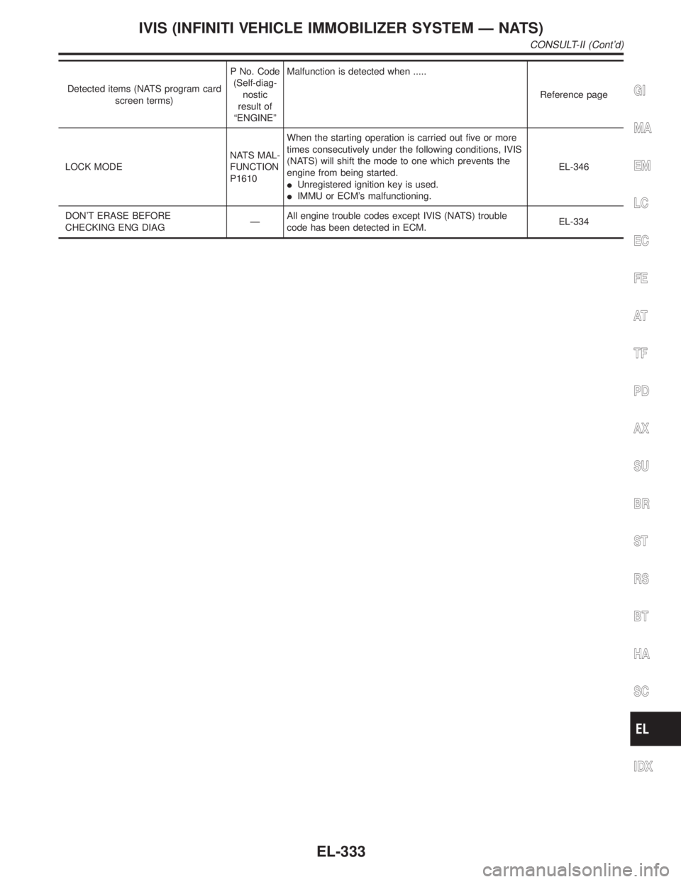
Detected items (NATS program card
screen terms)P No. Code
(Self-diag-
nostic
result of
ªENGINEºMalfunction is detected when .....
Reference page
LOCK MODENATS MAL-
FUNCTION
P1610When the starting operation is carried out five or more
times consecutively under the following conditions, IVIS
(NATS) will shift the mode to one which prevents the
engine from being started.
IUnregistered ignition key is used.
IIMMU or ECM's malfunctioning.EL-346
DON'T ERASE BEFORE
CHECKING ENG DIAGÐAll engine trouble codes except IVIS (NATS) trouble
code has been detected in ECM.EL-334GI
MA
EM
LC
EC
FE
AT
TF
PD
AX
SU
BR
ST
RS
BT
HA
SC
IDX
IVIS (INFINITI VEHICLE IMMOBILIZER SYSTEM Ð NATS)
CONSULT-II (Cont'd)
EL-333
Page 1520 of 2395
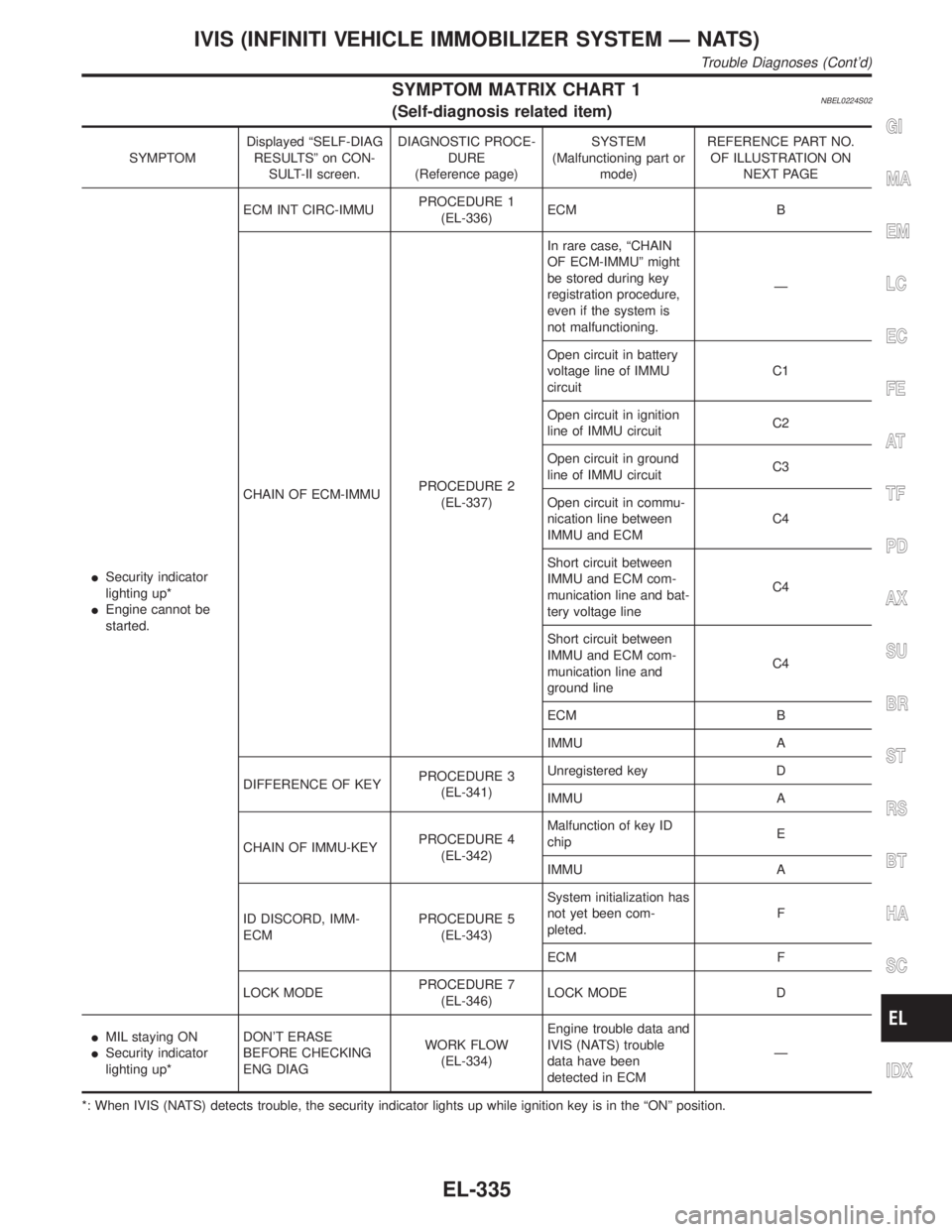
SYMPTOM MATRIX CHART 1NBEL0224S02(Self-diagnosis related item)
SYMPTOMDisplayed ªSELF-DIAG
RESULTSº on CON-
SULT-II screen.DIAGNOSTIC PROCE-
DURE
(Reference page)SYSTEM
(Malfunctioning part or
mode)REFERENCE PART NO.
OF ILLUSTRATION ON
NEXT PAGE
ISecurity indicator
lighting up*
IEngine cannot be
started.ECM INT CIRC-IMMUPROCEDURE 1
(EL-336)ECM B
CHAIN OF ECM-IMMUPROCEDURE 2
(EL-337)In rare case, ªCHAIN
OF ECM-IMMUº might
be stored during key
registration procedure,
even if the system is
not malfunctioning.Ð
Open circuit in battery
voltage line of IMMU
circuitC1
Open circuit in ignition
line of IMMU circuitC2
Open circuit in ground
line of IMMU circuitC3
Open circuit in commu-
nication line between
IMMU and ECMC4
Short circuit between
IMMU and ECM com-
munication line and bat-
tery voltage lineC4
Short circuit between
IMMU and ECM com-
munication line and
ground lineC4
ECM B
IMMU A
DIFFERENCE OF KEYPROCEDURE 3
(EL-341)Unregistered key D
IMMU A
CHAIN OF IMMU-KEYPROCEDURE 4
(EL-342)Malfunction of key ID
chipE
IMMU A
ID DISCORD, IMM-
ECMPROCEDURE 5
(EL-343)System initialization has
not yet been com-
pleted.F
ECM F
LOCK MODEPROCEDURE 7
(EL-346)LOCK MODE D
IMIL staying ON
ISecurity indicator
lighting up*DON'T ERASE
BEFORE CHECKING
ENG DIAGWORK FLOW
(EL-334)Engine trouble data and
IVIS (NATS) trouble
data have been
detected in ECMÐ
*: When IVIS (NATS) detects trouble, the security indicator lights up while ignition key is in the ªONº position.
GI
MA
EM
LC
EC
FE
AT
TF
PD
AX
SU
BR
ST
RS
BT
HA
SC
IDX
IVIS (INFINITI VEHICLE IMMOBILIZER SYSTEM Ð NATS)
Trouble Diagnoses (Cont'd)
EL-335
Page 1527 of 2395
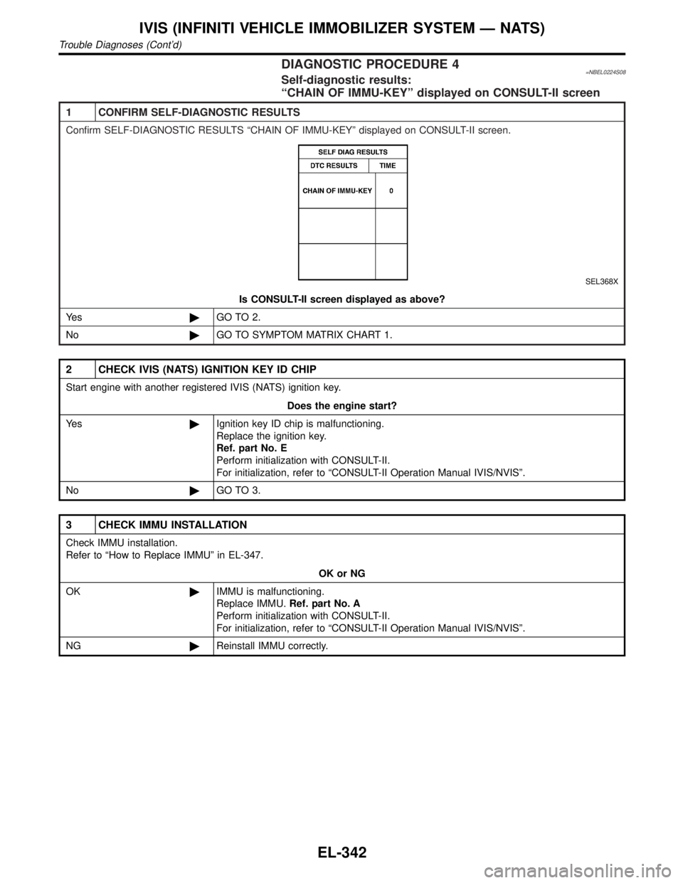
DIAGNOSTIC PROCEDURE 4=NBEL0224S08Self-diagnostic results:
ªCHAIN OF IMMU-KEYº displayed on CONSULT-II screen
1 CONFIRM SELF-DIAGNOSTIC RESULTS
Confirm SELF-DIAGNOSTIC RESULTS ªCHAIN OF IMMU-KEYº displayed on CONSULT-II screen.
SEL368X
Is CONSULT-II screen displayed as above?
Ye s©GO TO 2.
No©GO TO SYMPTOM MATRIX CHART 1.
2 CHECK IVIS (NATS) IGNITION KEY ID CHIP
Start engine with another registered IVIS (NATS) ignition key.
Does the engine start?
Ye s©Ignition key ID chip is malfunctioning.
Replace the ignition key.
Ref. part No. E
Perform initialization with CONSULT-II.
For initialization, refer to ªCONSULT-II Operation Manual IVIS/NVISº.
No©GO TO 3.
3 CHECK IMMU INSTALLATION
Check IMMU installation.
Refer to ªHow to Replace IMMUº in EL-347.
OK or NG
OK©IMMU is malfunctioning.
Replace IMMU.Ref. part No. A
Perform initialization with CONSULT-II.
For initialization, refer to ªCONSULT-II Operation Manual IVIS/NVISº.
NG©Reinstall IMMU correctly.
IVIS (INFINITI VEHICLE IMMOBILIZER SYSTEM Ð NATS)
Trouble Diagnoses (Cont'd)
EL-342
Page 1529 of 2395
![INFINITI QX4 2001 Factory Service Manual DIAGNOSTIC PROCEDURE 6=NBEL0224S10ªSECURITY INDICATOR LAMP DOES NOT LIGHT UPº
1 CHECK FUSE
Check 10A fuse [No. 12, located in the fuse block (J/B)].
Is 10A fuse OK?
Ye s©GO TO 2.
No©Replace fuse.
INFINITI QX4 2001 Factory Service Manual DIAGNOSTIC PROCEDURE 6=NBEL0224S10ªSECURITY INDICATOR LAMP DOES NOT LIGHT UPº
1 CHECK FUSE
Check 10A fuse [No. 12, located in the fuse block (J/B)].
Is 10A fuse OK?
Ye s©GO TO 2.
No©Replace fuse.](/manual-img/42/57027/w960_57027-1528.png)
DIAGNOSTIC PROCEDURE 6=NBEL0224S10ªSECURITY INDICATOR LAMP DOES NOT LIGHT UPº
1 CHECK FUSE
Check 10A fuse [No. 12, located in the fuse block (J/B)].
Is 10A fuse OK?
Ye s©GO TO 2.
No©Replace fuse.
2 CHECK SECURITY INDICATOR LAMP
1. Install 10A fuse.
2. Perform initialization with CONSULT-II.
For initialization, refer to ªCONSULT-II Operation Manual IVIS/NVISº.
3. Turn ignition switch OFF.
4. Start engine and turn ignition switch OFF.
5. Check the security indicator lamp lighting.
Security indicator lamp should be blinking.
OK or NG
OK©INSPECTION END
NG©GO TO 3.
3 CHECK SECURITY INDICATOR LAMP POWER SUPPLY CIRCUIT
1. Disconnect security indicator lamp connector.
2. Check voltage between security indicator lamp connector terminal 1 and ground.
SEL370X
OK or NG
OK©GO TO 4.
NG©Check harness for open or short between fuse and security indicator lamp.
4 CHECK SECURITY INDICATOR LAMP
Check security Indicator Lamp.
Is security indicator lamp OK?
Ye s©GO TO 5.
No©Replace security indicator lamp.
IVIS (INFINITI VEHICLE IMMOBILIZER SYSTEM Ð NATS)
Trouble Diagnoses (Cont'd)
EL-344
Page 1531 of 2395
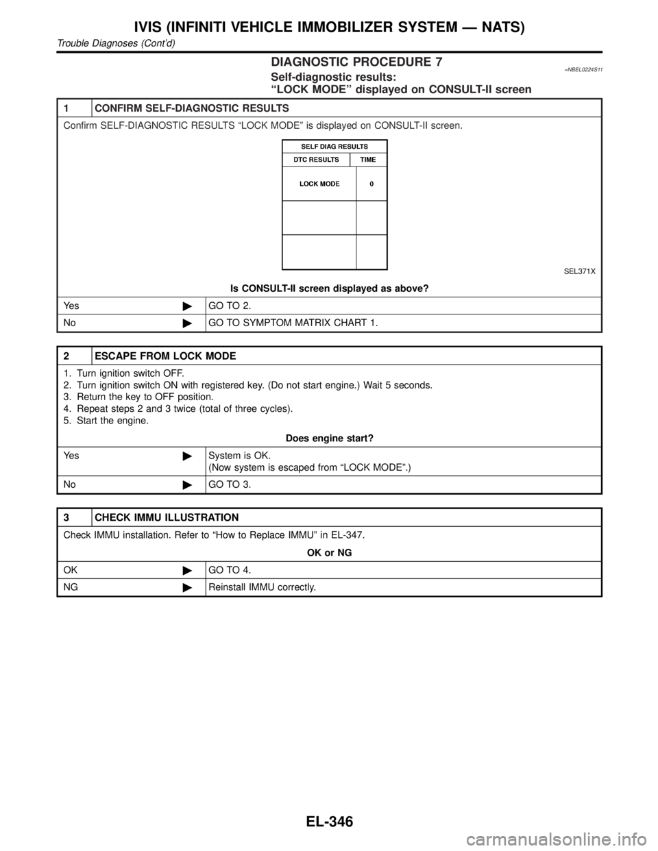
DIAGNOSTIC PROCEDURE 7=NBEL0224S11Self-diagnostic results:
ªLOCK MODEº displayed on CONSULT-II screen
1 CONFIRM SELF-DIAGNOSTIC RESULTS
Confirm SELF-DIAGNOSTIC RESULTS ªLOCK MODEº is displayed on CONSULT-II screen.
SEL371X
Is CONSULT-II screen displayed as above?
Ye s©GO TO 2.
No©GO TO SYMPTOM MATRIX CHART 1.
2 ESCAPE FROM LOCK MODE
1. Turn ignition switch OFF.
2. Turn ignition switch ON with registered key. (Do not start engine.) Wait 5 seconds.
3. Return the key to OFF position.
4. Repeat steps 2 and 3 twice (total of three cycles).
5. Start the engine.
Does engine start?
Ye s©System is OK.
(Now system is escaped from ªLOCK MODEº.)
No©GO TO 3.
3 CHECK IMMU ILLUSTRATION
Check IMMU installation. Refer to ªHow to Replace IMMUº in EL-347.
OK or NG
OK©GO TO 4.
NG©Reinstall IMMU correctly.
IVIS (INFINITI VEHICLE IMMOBILIZER SYSTEM Ð NATS)
Trouble Diagnoses (Cont'd)
EL-346
Page 1565 of 2395
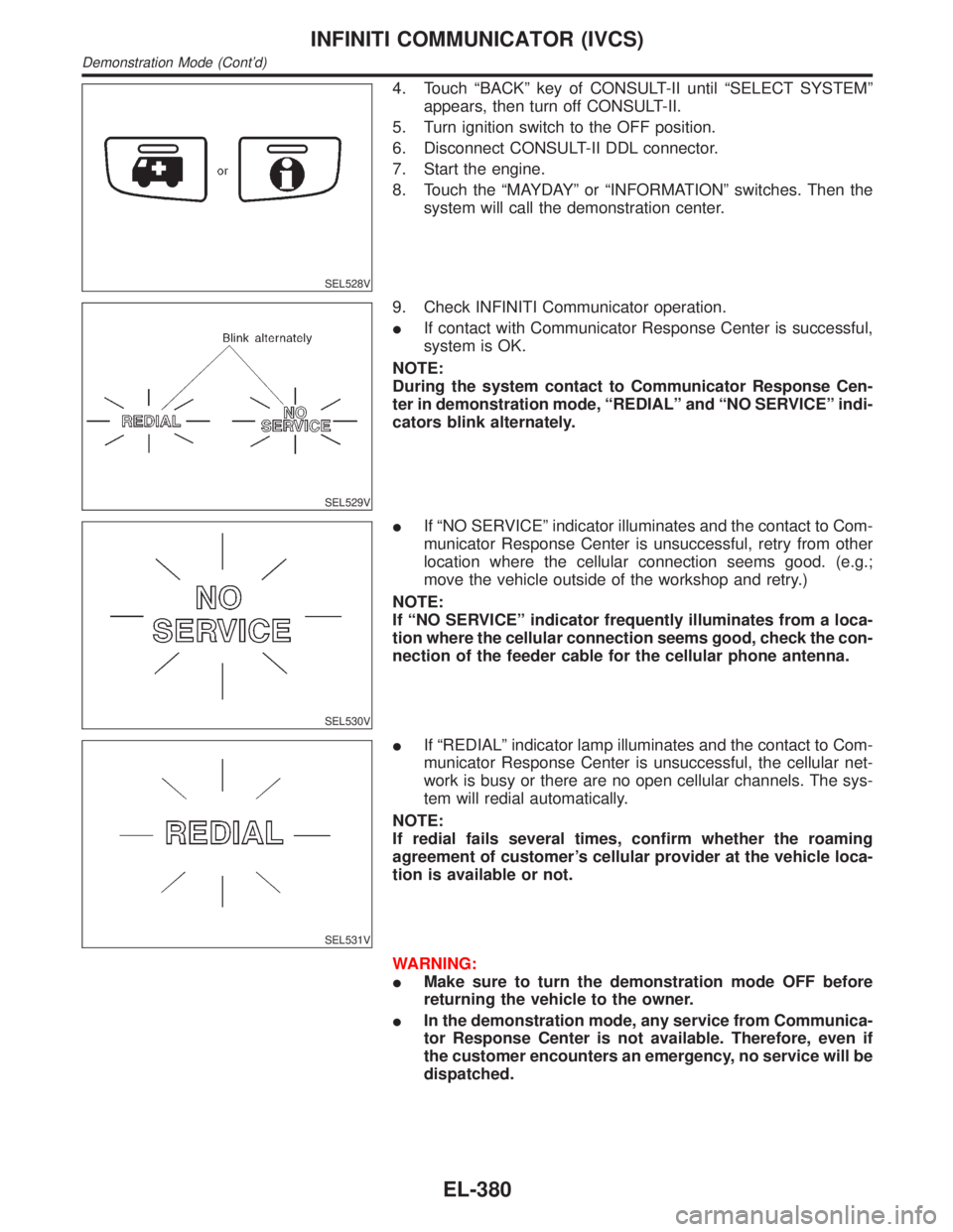
SEL528V
4. Touch ªBACKº key of CONSULT-II until ªSELECT SYSTEMº
appears, then turn off CONSULT-II.
5. Turn ignition switch to the OFF position.
6. Disconnect CONSULT-II DDL connector.
7. Start the engine.
8. Touch the ªMAYDAYº or ªINFORMATIONº switches. Then the
system will call the demonstration center.
SEL529V
9. Check INFINITI Communicator operation.
IIf contact with Communicator Response Center is successful,
system is OK.
NOTE:
During the system contact to Communicator Response Cen-
ter in demonstration mode, ªREDIALº and ªNO SERVICEº indi-
cators blink alternately.
SEL530V
IIf ªNO SERVICEº indicator illuminates and the contact to Com-
municator Response Center is unsuccessful, retry from other
location where the cellular connection seems good. (e.g.;
move the vehicle outside of the workshop and retry.)
NOTE:
If ªNO SERVICEº indicator frequently illuminates from a loca-
tion where the cellular connection seems good, check the con-
nection of the feeder cable for the cellular phone antenna.
SEL531V
IIf ªREDIALº indicator lamp illuminates and the contact to Com-
municator Response Center is unsuccessful, the cellular net-
work is busy or there are no open cellular channels. The sys-
tem will redial automatically.
NOTE:
If redial fails several times, confirm whether the roaming
agreement of customer's cellular provider at the vehicle loca-
tion is available or not.
WARNING:
IMake sure to turn the demonstration mode OFF before
returning the vehicle to the owner.
IIn the demonstration mode, any service from Communica-
tor Response Center is not available. Therefore, even if
the customer encounters an emergency, no service will be
dispatched.
INFINITI COMMUNICATOR (IVCS)
Demonstration Mode (Cont'd)
EL-380