Page 1657 of 2395

NBEM0007
SEM480G
SEM481G
JEM482G
SEM387C
1. Warm up engine.
2. Turn ignition switch OFF.
3. Release fuel pressure.
Refer to EC-39, ªFuel Pressure Releaseº.
4. Remove engine cover and throttle wire.
5. Remove air duct with air cleaner case.
6. Remove harness connectors and harness brackets around
ignition coils.
7. Remove throttle body.
8. Disconnect ignition coil with power transistor harness
connectors, then remove ignition coils.
9. Remove all spark plugs.
IClean area around plug with compressed air before removing
the spark plug.
10. Attach a compression tester to No. 1 cylinder.
11. Depress accelerator pedal fully to keep throttle valve wide
open.
12. Crank engine and record highest gauge indication.
13. Repeat the measurement on each cylinder as shown above.
IAlways use a fully-charged battery to obtain specified
engine speed.
Unit: kPa (kg/cm2, psi)/rpm
Standard MinimumDifference limit between
cylinders
1,275 (13.0, 185)/300 981 (10.0, 142)/300 98 (1.0, 14)/300
14. If compression in one or more cylinders is low:
a. Pour a small amount of engine oil into cylinders through spark
plug holes.
b. Retest compression.
IIf adding oil helps compression, piston rings may be worn
or damaged. If so, replace piston rings after checking pis-
ton.
IIf pressure stays low, a valve may be sticking or seating
improperly. Inspect and repair valve and valve seat. (Refer
to SDS, EM-76 and EM-79.) If valve or valve seat is dam-
aged excessively, replace them.
IIf compression stays low in two cylinders that are next to
each other:
a) The cylinder head gasket may be leaking, or
b) Both cylinders may have valve component damage. Inspect
and repair as necessary.
15. Install parts in reverse order of removal.
16. Perform ªSelf-diagnosis Procedureº referring to EC-72, ªHow to
Erase DTCº if any DTC appears.
MEASUREMENT OF COMPRESSION PRESSURE
EM-14
Page 1672 of 2395
SEM928E
InspectionNBEM0013Check for cracks and excessive wear at roller links. Replace
chain if necessary.
SEM930E
InstallationNBEM00141. Position crankshaft so that No. 1 piston is set at TDC on com-
pression stroke.
SEM929E
2. Install crankshaft sprocket on crankshaft.
IMake sure that mating marks on crankshaft sprocket face
front of engine.
SEM931E
3. Install lower chain guide on dowel pin, with front mark on the
guide facing upside.
SEM430G
4. Press and shrink the secondary chain tensioner sleeve, and fix
it using stopper pins.
ILubricate threads and seat surfaces of camshaft sprocket bolts
with new engine oil.
GI
MA
LC
EC
FE
AT
TF
PD
AX
SU
BR
ST
RS
BT
HA
SC
EL
IDX
TIMING CHAIN
Inspection
EM-29
Page 1693 of 2395
SEM653F
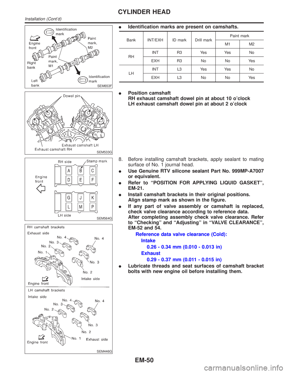
IIdentification marks are present on camshafts.
Bank INT/EXH ID mark Drill markPaint mark
M1 M2
RHINT R3 Yes Yes No
EXH R3 No No Yes
LHINT L3 Yes Yes No
EXH L3 No No Yes
SEM533G
IPosition camshaft
RH exhaust camshaft dowel pin at about 10 o'clock
LH exhaust camshaft dowel pin at about 2 o'clock
SEM564G
SEM446G
8. Before installing camshaft brackets, apply sealant to mating
surface of No. 1 journal head.
IUse Genuine RTV silicone sealant Part No. 999MP-A7007
or equivalent.
IRefer to ªPOSITION FOR APPLYING LIQUID GASKETº,
EM-21.
IInstall camshaft brackets in their original positions.
Align stamp mark as shown in the figure.
IIf any part of valve assembly or camshaft is replaced,
check valve clearance according to reference data.
After completing assembly check valve clearance. Refer
to ªCheckingº and ªAdjustingº in ªVALVE CLEARANCEº,
EM-52 and 54.
Reference data valve clearance (Cold):
Intake
0.26 - 0.34 mm (0.010 - 0.013 in)
Exhaust
0.29 - 0.37 mm (0.011 - 0.015 in)
ILubricate threads and seat surfaces of camshaft bracket
bolts with new engine oil before installing them.
CYLINDER HEAD
Installation (Cont'd)
EM-50
Page 1695 of 2395
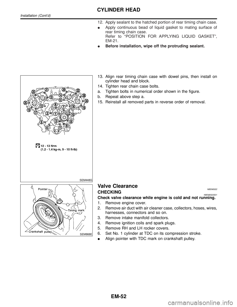
12. Apply sealant to the hatched portion of rear timing chain case.
IApply continuous bead of liquid gasket to mating surface of
rear timing chain case.
Refer to ªPOSITION FOR APPLYING LIQUID GASKETº,
EM-21.
IBefore installation, wipe off the protruding sealant.
SEM448G
13. Align rear timing chain case with dowel pins, then install on
cylinder head and block.
14. Tighten rear chain case bolts.
a. Tighten bolts in numerical order shown in the figure.
b. Repeat above step a.
15. Reinstall all removed parts in reverse order of removal.
SEM868E
Valve ClearanceNBEM0022CHECKINGNBEM0022S01Check valve clearance while engine is cold and not running.
1. Remove engine cover.
2. Remove air duct with air cleaner case, collectors, hoses, wires,
harnesses, connectors and so on.
3. Remove intake manifold collectors.
4. Remove ignition coils and spark plugs.
5. Remove RH and LH rocker covers.
6. Set No. 1 cylinder at TDC on its compression stroke.
IAlign pointer with TDC mark on crankshaft pulley.
CYLINDER HEAD
Installation (Cont'd)
EM-52
Page 1697 of 2395
SEM894E
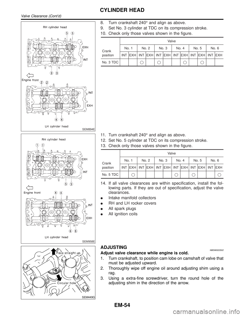
8. Turn crankshaft 240É and align as above.
9. Set No. 3 cylinder at TDC on its compression stroke.
10. Check only those valves shown in the figure.
Crank
positionValve
No. 1 No. 2 No. 3 No. 4 No. 5 No. 6
INT EXH INT EXH INT EXH INT EXH INT EXH INT EXH
No. 3 TDCqq qq
SEM958E
11. Turn crankshaft 240É and align as above.
12. Set No. 5 cylinder at TDC on its compression stroke.
13. Check only those valves shown in the figure.
Crank
positionValve
No. 1 No. 2 No. 3 No. 4 No. 5 No. 6
INT EXH INT EXH INT EXH INT EXH INT EXH INT EXH
No. 5 TDCqqqq
14. If all valve clearances are within specification, install the fol-
lowing parts. If they are out of specification, adjust the valve
clearances.
IIntake manifold collectors
IRH and LH rocker covers
IAll spark plugs
IAll ignition coils
SEM449G
ADJUSTINGNBEM0022S02Adjust valve clearance while engine is cold.
1. Turn crankshaft, to position cam lobe on camshaft of valve that
must be adjusted upward.
2. Thoroughly wipe off engine oil around adjusting shim using a
rag.
3. Using a extra-fine screwdriver, turn the round hole of the
adjusting shim in the direction of the arrow.
CYLINDER HEAD
Valve Clearance (Cont'd)
EM-54
Page 1708 of 2395
SEM038F
SEM003F
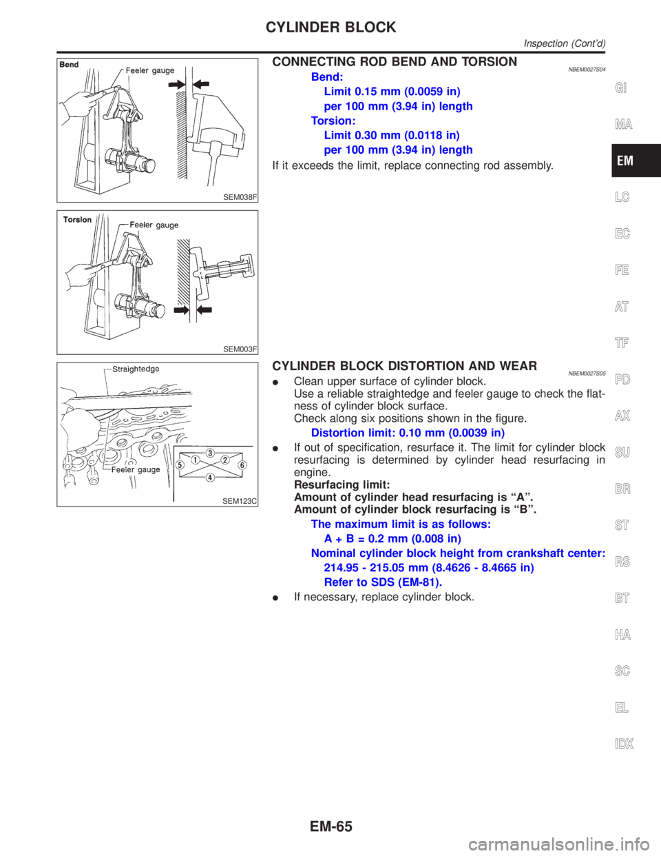
CONNECTING ROD BEND AND TORSIONNBEM0027S04Bend:
Limit 0.15 mm (0.0059 in)
per 100 mm (3.94 in) length
Torsion:
Limit 0.30 mm (0.0118 in)
per 100 mm (3.94 in) length
If it exceeds the limit, replace connecting rod assembly.
SEM123C
CYLINDER BLOCK DISTORTION AND WEARNBEM0027S05IClean upper surface of cylinder block.
Use a reliable straightedge and feeler gauge to check the flat-
ness of cylinder block surface.
Check along six positions shown in the figure.
Distortion limit: 0.10 mm (0.0039 in)
IIf out of specification, resurface it. The limit for cylinder block
resurfacing is determined by cylinder head resurfacing in
engine.
Resurfacing limit:
Amount of cylinder head resurfacing is ªAº.
Amount of cylinder block resurfacing is ªBº.
The maximum limit is as follows:
A + B = 0.2 mm (0.008 in)
Nominal cylinder block height from crankshaft center:
214.95 - 215.05 mm (8.4626 - 8.4665 in)
Refer to SDS (EM-81).
IIf necessary, replace cylinder block.
GI
MA
LC
EC
FE
AT
TF
PD
AX
SU
BR
ST
RS
BT
HA
SC
EL
IDX
CYLINDER BLOCK
Inspection (Cont'd)
EM-65
Page 1733 of 2395
Removal and InstallationNBFE0004WARNING:
When replacing fuel line parts, be sure to observe the follow-
ing:
IPut a ªCAUTION: INFLAMMABLEº sign in workshop.
IDo not smoke while servicing fuel system. Keep open
flames and sparks away from work area.
IBe sure to furnish the workshop with a CO
2fire extin-
guisher.
CAUTION:
IBefore removing fuel line parts, carry out the following
procedures:
a) Put drained fuel in an explosion-proof container and put
lid on securely.
b) Release fuel pressure from fuel line. Refer to MA-16,
ªChanging Fuel Filterº.
c) Disconnect battery ground cable.
IAlways replace O-ring with new ones.
IDo not kink or twist hose and tube when they are installed.
IDo not tighten hose clamps excessively to avoid damag-
ing hoses.
IWhen installing fuel check valve, be careful of its desig-
nated direction. Refer to EC-32, ªEVAPORATIVE EMIS-
SION SYSTEMº.
IAfter installation, run engine and check for fuel leaks at
connections.
FUEL SYSTEM
Removal and Installation
FE-4
Page 1737 of 2395
Removal and InstallationNBFE0005CAUTION:
IAlways replace exhaust gaskets with new ones when reassembling.
IWith engine running, check all tube connections for exhaust gas leaks, and entire system for
unusual noises.
ICheck to ensure that mounting brackets and mounting insulators are installed properly and free
from undue stress. Improper installation could result in excessive noise or vibration.
IDiscard any heated oxygen sensor which has been dropped from a height of more than 0.5 m (19.7
in) onto a hard surface such as a concrete floor; use a new one.
IBefore installing new oxygen sensor, clean exhaust system threads using Oxygen Sensor Thread
Cleaner tool J-43897-18 of J-43897-12 and approved anti-seize lubricant.
IDo not overtorque the oxygen sensor. Doing so may cause damage to the oxygen sensor, result-
ing in the MIL coming on.
EXHAUST SYSTEM
Removal and Installation
FE-8