Page 1736 of 2395

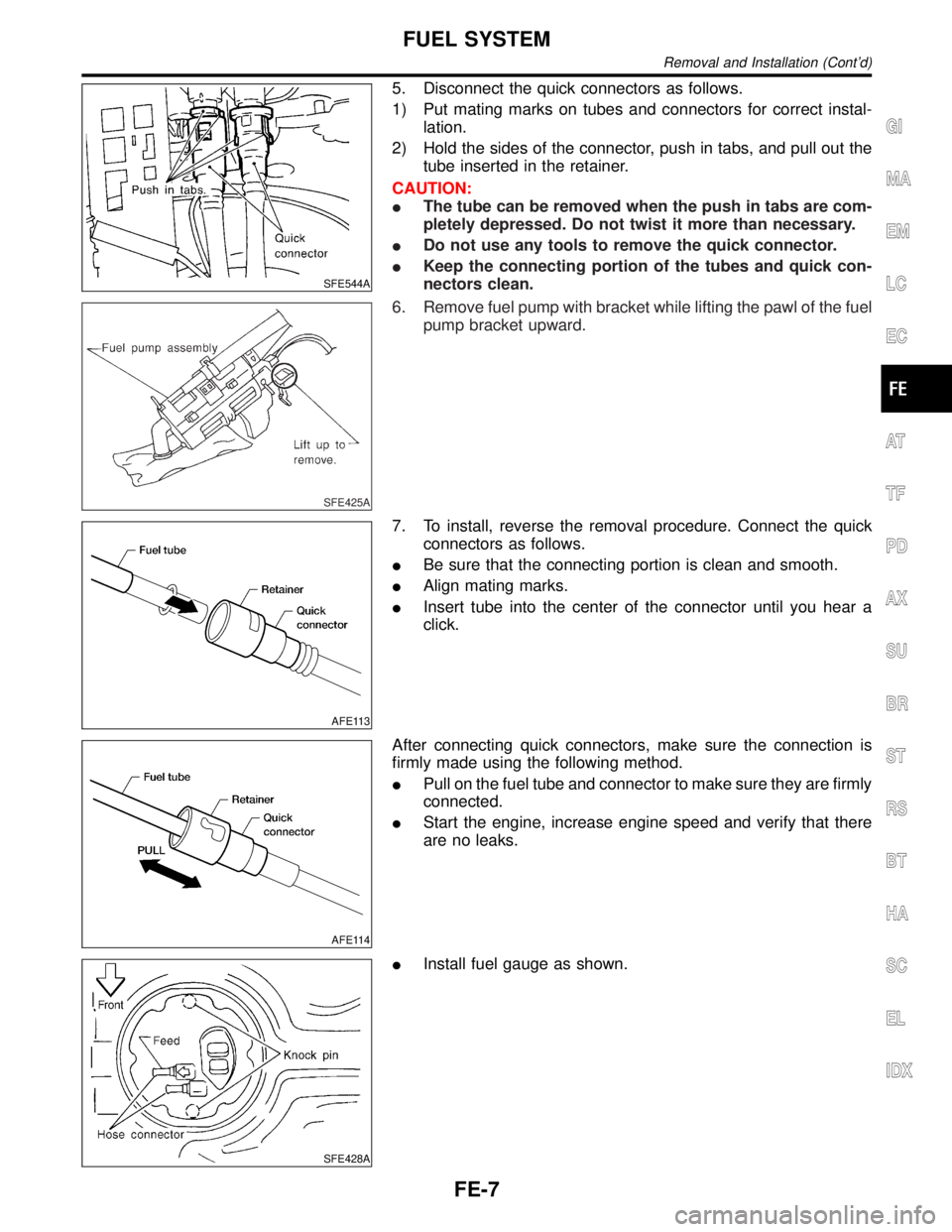
SFE544A
5. Disconnect the quick connectors as follows.
1) Put mating marks on tubes and connectors for correct instal-
lation.
2) Hold the sides of the connector, push in tabs, and pull out the
tube inserted in the retainer.
CAUTION:
IThe tube can be removed when the push in tabs are com-
pletely depressed. Do not twist it more than necessary.
IDo not use any tools to remove the quick connector.
IKeep the connecting portion of the tubes and quick con-
nectors clean.
SFE425A
6. Remove fuel pump with bracket while lifting the pawl of the fuel
pump bracket upward.
AFE113
7. To install, reverse the removal procedure. Connect the quick
connectors as follows.
IBe sure that the connecting portion is clean and smooth.
IAlign mating marks.
IInsert tube into the center of the connector until you hear a
click.
AFE114
After connecting quick connectors, make sure the connection is
firmly made using the following method.
IPull on the fuel tube and connector to make sure they are firmly
connected.
IStart the engine, increase engine speed and verify that there
are no leaks.
SFE428A
IInstall fuel gauge as shown.
GI
MA
EM
LC
EC
AT
TF
PD
AX
SU
BR
ST
RS
BT
HA
SC
EL
IDX
FUEL SYSTEM
Removal and Installation (Cont'd)
FE-7
Page 1737 of 2395
Removal and InstallationNBFE0005CAUTION:
IAlways replace exhaust gaskets with new ones when reassembling.
IWith engine running, check all tube connections for exhaust gas leaks, and entire system for
unusual noises.
ICheck to ensure that mounting brackets and mounting insulators are installed properly and free
from undue stress. Improper installation could result in excessive noise or vibration.
IDiscard any heated oxygen sensor which has been dropped from a height of more than 0.5 m (19.7
in) onto a hard surface such as a concrete floor; use a new one.
IBefore installing new oxygen sensor, clean exhaust system threads using Oxygen Sensor Thread
Cleaner tool J-43897-18 of J-43897-12 and approved anti-seize lubricant.
IDo not overtorque the oxygen sensor. Doing so may cause damage to the oxygen sensor, result-
ing in the MIL coming on.
EXHAUST SYSTEM
Removal and Installation
FE-8
Page 1738 of 2395
SFE636A
1. Heated oxygen sensor 2 (rear)
(bank 1)
2. Front tube
3. Heated oxygen sensor 2 (rear)
(bank 2)4. Dynamic damper (If so equipped)
5. Mounting rubber
6. Clamp
7. Mounting bracket8. Mounting rubber
9. Main muffler
10. Post muffler
11. TWC (under floor)
GI
MA
EM
LC
EC
AT
TF
PD
AX
SU
BR
ST
RS
BT
HA
SC
EL
IDX
EXHAUST SYSTEM
Removal and Installation (Cont'd)
FE-9
Page 1739 of 2395
SFE652A
1. Heated oxygen sensor 2 (rear)
(bank 1)
2. Front tube
3. Heated oxygen sensor 2 (rear)
(bank 2)4. Mounting bracket
5. Mounting rubber
6. Main muffler7. Post muffler
8. Dynamic damper (If so equipped)
9. TWC (under floor)
EXHAUST SYSTEM
Removal and Installation (Cont'd)
FE-10
Page 1740 of 2395
MEL874F
MEL875F
InstallationNBEL0146To install SMJ, tighten bolts until orange ªfulltightº mark appears
and then retighten to specified torque as required.
:3-5N´m
(0.3 - 0.5 kg-m, 26 - 43 in-lb)
CAUTION:
Do not overtighten bolts, otherwise, they may be damaged.
SUPER MULTIPLE JUNCTION (SMJ)
Installation
Page 1748 of 2395

PrecautionsNBGI0001Observe the following precautions to ensure safe and proper
servicing. These precautions are not described in each indi-
vidual section.
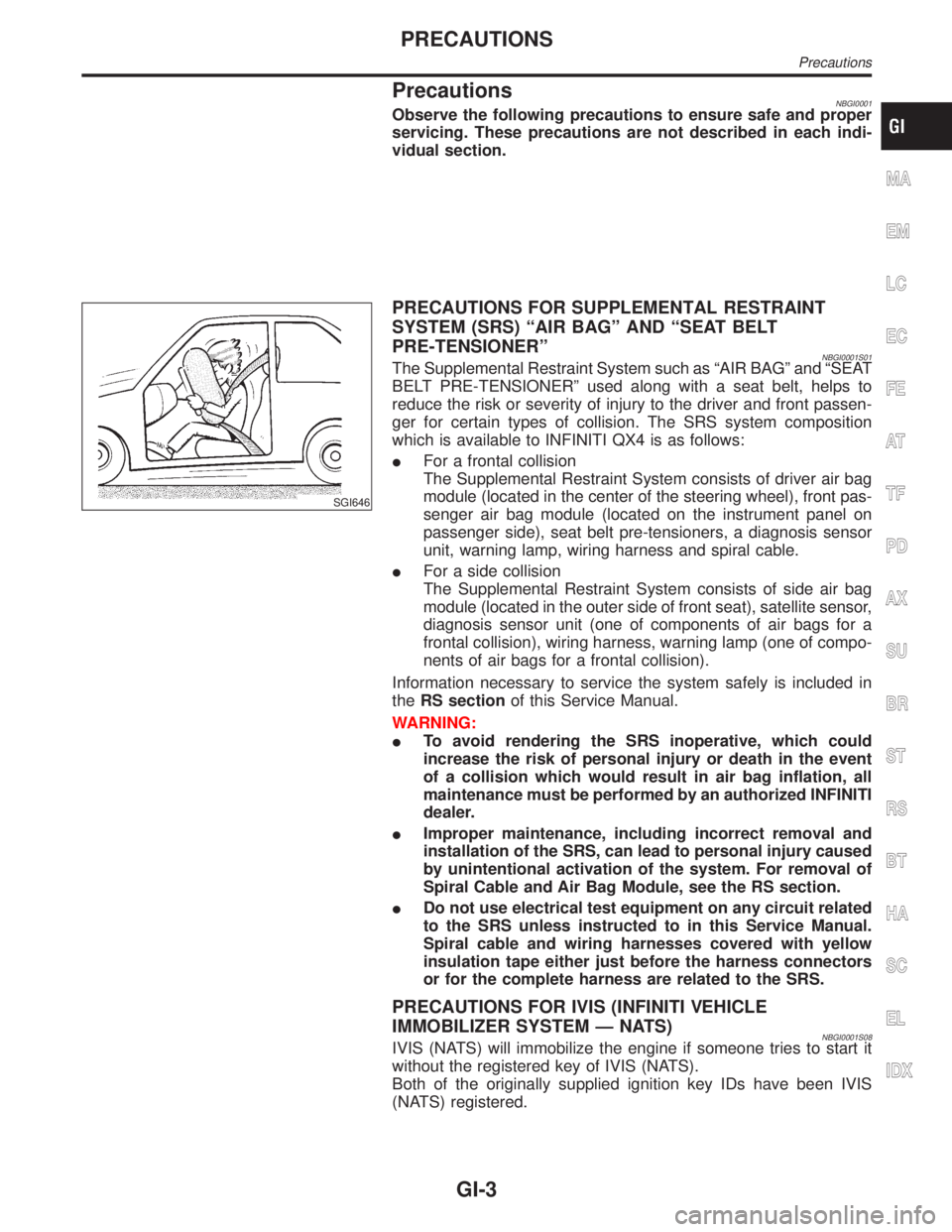
SGI646
PRECAUTIONS FOR SUPPLEMENTAL RESTRAINT
SYSTEM (SRS) ªAIR BAGº AND ªSEAT BELT
PRE-TENSIONERº
NBGI0001S01The Supplemental Restraint System such as ªAIR BAGº and ªSEAT
BELT PRE-TENSIONERº used along with a seat belt, helps to
reduce the risk or severity of injury to the driver and front passen-
ger for certain types of collision. The SRS system composition
which is available to INFINITI QX4 is as follows:
IFor a frontal collision
The Supplemental Restraint System consists of driver air bag
module (located in the center of the steering wheel), front pas-
senger air bag module (located on the instrument panel on
passenger side), seat belt pre-tensioners, a diagnosis sensor
unit, warning lamp, wiring harness and spiral cable.
IFor a side collision
The Supplemental Restraint System consists of side air bag
module (located in the outer side of front seat), satellite sensor,
diagnosis sensor unit (one of components of air bags for a
frontal collision), wiring harness, warning lamp (one of compo-
nents of air bags for a frontal collision).
Information necessary to service the system safely is included in
theRS sectionof this Service Manual.
WARNING:
ITo avoid rendering the SRS inoperative, which could
increase the risk of personal injury or death in the event
of a collision which would result in air bag inflation, all
maintenance must be performed by an authorized INFINITI
dealer.
IImproper maintenance, including incorrect removal and
installation of the SRS, can lead to personal injury caused
by unintentional activation of the system. For removal of
Spiral Cable and Air Bag Module, see the RS section.
IDo not use electrical test equipment on any circuit related
to the SRS unless instructed to in this Service Manual.
Spiral cable and wiring harnesses covered with yellow
insulation tape either just before the harness connectors
or for the complete harness are related to the SRS.
PRECAUTIONS FOR IVIS (INFINITI VEHICLE
IMMOBILIZER SYSTEM Ð NATS)
NBGI0001S08IVIS (NATS) will immobilize the engine if someone tries to start it
without the registered key of IVIS (NATS).
Both of the originally supplied ignition key IDs have been IVIS
(NATS) registered.
MA
EM
LC
EC
FE
AT
TF
PD
AX
SU
BR
ST
RS
BT
HA
SC
EL
IDX
PRECAUTIONS
Precautions
GI-3
Page 1752 of 2395

Do not place the vehicle on flammable material. Keep flammable
material off the exhaust pipe and the three way catalyst.
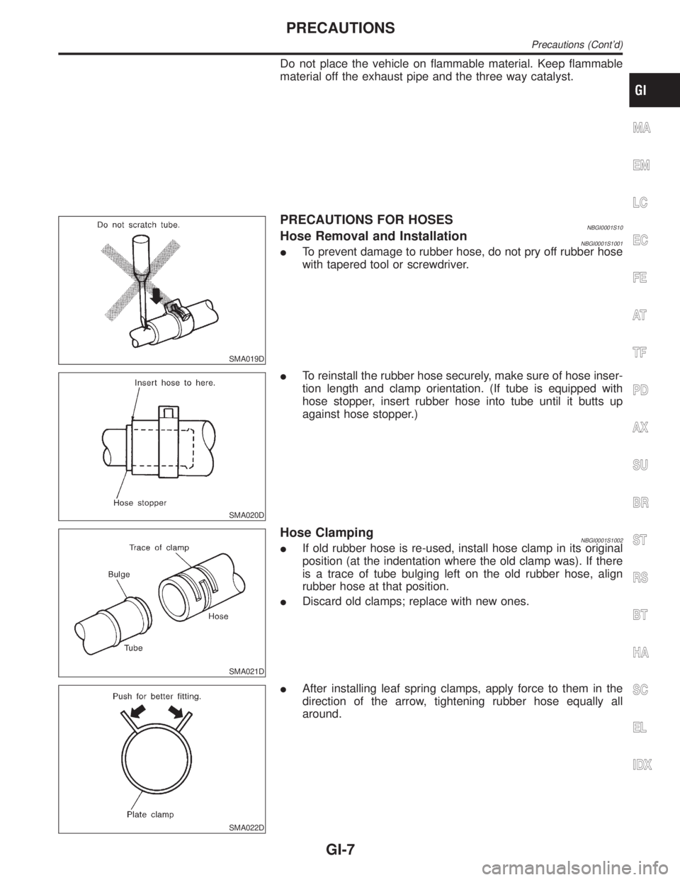
SMA019D
PRECAUTIONS FOR HOSESNBGI0001S10Hose Removal and InstallationNBGI0001S1001ITo prevent damage to rubber hose, do not pry off rubber hose
with tapered tool or screwdriver.
SMA020D
ITo reinstall the rubber hose securely, make sure of hose inser-
tion length and clamp orientation. (If tube is equipped with
hose stopper, insert rubber hose into tube until it butts up
against hose stopper.)
SMA021D
Hose ClampingNBGI0001S1002IIf old rubber hose is re-used, install hose clamp in its original
position (at the indentation where the old clamp was). If there
is a trace of tube bulging left on the old rubber hose, align
rubber hose at that position.
IDiscard old clamps; replace with new ones.
SMA022D
IAfter installing leaf spring clamps, apply force to them in the
direction of the arrow, tightening rubber hose equally all
around.
MA
EM
LC
EC
FE
AT
TF
PD
AX
SU
BR
ST
RS
BT
HA
SC
EL
IDX
PRECAUTIONS
Precautions (Cont'd)
GI-7
Page 1771 of 2395

Engine Compartment
There are several reasons a vehicle or engine vibration could
cause an electrical complaint. Some of the things to check for are:
IConnectors not fully seated.
IWiring harness not long enough and is being stressed due to
engine vibrations or rocking.
IWires laying across brackets or moving components.
ILoose, dirty or corroded ground wires.
IWires routed too close to hot components.
To inspect components under the hood, start by verifying the integ-
rity of ground connections. (Refer to GROUND INSPECTION
described later.) First check that the system is properly grounded.
Then check for loose connection bygently shakingthe wiring or
components as previously explained. Using the wiring diagrams
inspect the wiring for continuity.
Behind The Instrument Panel
An improperly routed or improperly clamped harness can become
pinched during accessory installation. Vehicle vibration can aggra-
vate a harness which is routed along a bracket or near a screw.
Under Seating Areas
An unclamped or loose harness can cause wiring to be pinched by
seat components (such as slide guides) during vehicle vibration. If
the wiring runs under seating areas, inspect wire routing for pos-
sible damage or pinching.
SGI842
HEAT SENSITIVENBGI0004S0203The owner's problem may occur during hot weather or after car has
sat for a short time. In such cases you will want to check for a heat
sensitive condition.
To determine if an electrical component is heat sensitive, heat the
component with a heat gun or equivalent.
Do not heat components above 60ÉC (140ÉF).If incident occurs
while heating the unit, either replace or properly insulate the com-
ponent.
SGI843
FREEZINGNBGI0004S0204The customer may indicate the incident goes away after the car
warms up (winter time). The cause could be related to water freez-
ing somewhere in the wiring/electrical system.
There are two methods to check for this. The first is to arrange for
the owner to leave his car overnight. Make sure it will get cold
enough to demonstrate his complaint. Leave the car parked out-
side overnight. In the morning, do a quick and thorough diagnosis
of those electrical components which could be affected.
HOW TO PERFORM EFFICIENT DIAGNOSIS FOR AN ELECTRICAL INCIDENT
Incident Simulation Tests (Cont'd)
GI-26