Page 1691 of 2395
SEM532G
3. Before installing the cylinder head gasket, be sure that No. 1
cylinder is at TDC.
IAt this time, the crankshaft key should face toward the right
bank.
SEM445G
4. Install cylinder heads with new gaskets.
IDo not rotate crankshaft and camshaft separately, or
valves will strike piston heads.
SEM957E
CAUTION:
Cylinder head bolts are tightened by plastic zone tightening
method. Whenever the size difference between d1 and d2
exceeds the limit, replace them with new ones.
Limit (d1 - d2):
0.11 mm (0.0043 in)
ILubricate threads and seat surfaces of the bolts with new
engine oil.
CYLINDER HEAD
Installation (Cont'd)
EM-48
Page 1692 of 2395
SEM877EA
SEM878EA
SEM879EA
5. Install cylinder head outside bolts.
ITightening procedure:
a.Tighten all bolts to 98 N´m (10 kg-m, 72 ft-lb).
b.Completely loosen all bolts.
c.Tighten all bolts to 34 to 44 N´m (3.5 to 4.5 kg-m, 25 to 33
ft-lb).
d.Turn all bolts 90 to 95 degrees clockwise.
e.Turn all bolts 90 to 95 degrees clockwise.
ITighten in numerical order shown in the figure.
SEM444G
6. Install camshaft chain tensioners on both sides of cylinder
head.
SEM652F
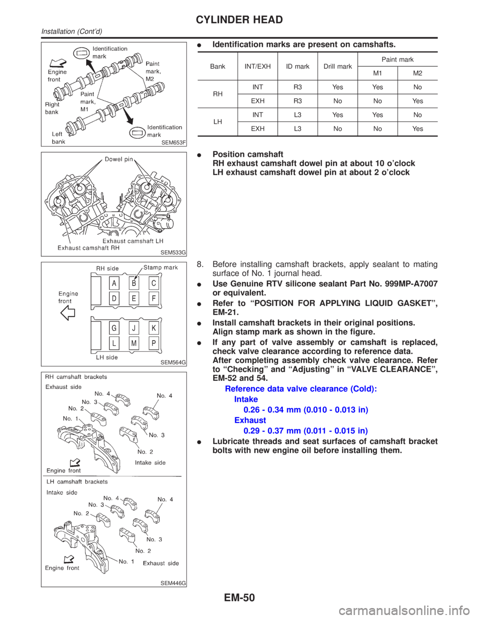
7. Install exhaust and intake camshafts and camshaft brackets.
IIntake camshaft has a drill mark on camshaft sprocket
mounting flange. Install it on the intake side.
GI
MA
LC
EC
FE
AT
TF
PD
AX
SU
BR
ST
RS
BT
HA
SC
EL
IDX
CYLINDER HEAD
Installation (Cont'd)
EM-49
Page 1693 of 2395

SEM653F
IIdentification marks are present on camshafts.
Bank INT/EXH ID mark Drill markPaint mark
M1 M2
RHINT R3 Yes Yes No
EXH R3 No No Yes
LHINT L3 Yes Yes No
EXH L3 No No Yes
SEM533G
IPosition camshaft
RH exhaust camshaft dowel pin at about 10 o'clock
LH exhaust camshaft dowel pin at about 2 o'clock
SEM564G
SEM446G
8. Before installing camshaft brackets, apply sealant to mating
surface of No. 1 journal head.
IUse Genuine RTV silicone sealant Part No. 999MP-A7007
or equivalent.
IRefer to ªPOSITION FOR APPLYING LIQUID GASKETº,
EM-21.
IInstall camshaft brackets in their original positions.
Align stamp mark as shown in the figure.
IIf any part of valve assembly or camshaft is replaced,
check valve clearance according to reference data.
After completing assembly check valve clearance. Refer
to ªCheckingº and ªAdjustingº in ªVALVE CLEARANCEº,
EM-52 and 54.
Reference data valve clearance (Cold):
Intake
0.26 - 0.34 mm (0.010 - 0.013 in)
Exhaust
0.29 - 0.37 mm (0.011 - 0.015 in)
ILubricate threads and seat surfaces of camshaft bracket
bolts with new engine oil before installing them.
CYLINDER HEAD
Installation (Cont'd)
EM-50
Page 1694 of 2395
SEM885EA
SEM886EA
ITighten the camshaft brackets in the following steps.
Step Tightening torque Tightening order
1 1.96 N´m (0.2 kg-m, 17 in-lb)Tighten in the order of 7 to 10,
then tighten 1 to 6.
2 5.88 N´m (0.6 kg-m, 52 in-lb) Tighten in the numerical order.
39.02 - 11.8 N´m (0.92 - 1.20 kg-m,
79.9 - 104.2 in-lb)Tighten in the numerical order.
SEM443G
9. Install CVTC valves.
SEM534G
10. Install O-rings to cylinder block.
SEM447G
11. Install O-rings to cylinder head.
GI
MA
LC
EC
FE
AT
TF
PD
AX
SU
BR
ST
RS
BT
HA
SC
EL
IDX
CYLINDER HEAD
Installation (Cont'd)
EM-51
Page 1695 of 2395

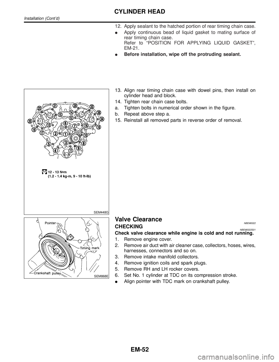
12. Apply sealant to the hatched portion of rear timing chain case.
IApply continuous bead of liquid gasket to mating surface of
rear timing chain case.
Refer to ªPOSITION FOR APPLYING LIQUID GASKETº,
EM-21.
IBefore installation, wipe off the protruding sealant.
SEM448G
13. Align rear timing chain case with dowel pins, then install on
cylinder head and block.
14. Tighten rear chain case bolts.
a. Tighten bolts in numerical order shown in the figure.
b. Repeat above step a.
15. Reinstall all removed parts in reverse order of removal.
SEM868E
Valve ClearanceNBEM0022CHECKINGNBEM0022S01Check valve clearance while engine is cold and not running.
1. Remove engine cover.
2. Remove air duct with air cleaner case, collectors, hoses, wires,
harnesses, connectors and so on.
3. Remove intake manifold collectors.
4. Remove ignition coils and spark plugs.
5. Remove RH and LH rocker covers.
6. Set No. 1 cylinder at TDC on its compression stroke.
IAlign pointer with TDC mark on crankshaft pulley.
CYLINDER HEAD
Installation (Cont'd)
EM-52
Page 1700 of 2395

Removal and InstallationNBEM0042WARNING:
ISituate vehicle on a flat and solid surface.
IPlace chocks at front and back of rear wheels.
IDo not remove engine until exhaust system has com-
pletely cooled off. Otherwise, you may burn yourself
and/or fire may break out in fuel line.
IFor safety during subsequent steps, the tension of wires
should be slackened against the engine.
IBefore disconnecting fuel hose, release fuel pressure
from fuel line.
Refer to EC-39, ªFuel Pressure Releaseº.
IBefore removing front axle from transmission, place
safety stands under designated front supporting points.
Refer to GI section for lifting points and towing.
IBe sure to hoist engine and transmission in a safe man-
ner.
IFor engines not equipped with engine slingers, attach
proper slingers and bolts described in PARTS CATALOG.
CAUTION:
IWhen lifting engine, be careful not to strike adjacent parts,
especially accelerator wire casing, brake lines, and brake
master cylinder.
IIn hoisting the engine, always use engine slingers in a
safe manner.
IBefore separating engine and transmission, remove
crankshaft position sensor (POS) from the assembly.
IAlways take extra care not to damage edge of crankshaft
position sensor (POS), or ring gear teeth.GI
MA
LC
EC
FE
AT
TF
PD
AX
SU
BR
ST
RS
BT
HA
SC
EL
IDX
ENGINE ASSEMBLY
Removal and Installation
EM-57
Page 1701 of 2395
REMOVALNBEM0042S01Front Engine MountingNBEM0042S0101
SEM458G
ENGINE ASSEMBLY
Removal and Installation (Cont'd)
EM-58
Page 1702 of 2395

Rear Engine MountingNBEM0042S0102
SEM459G
SEM605G
SEM461G
SEM324F
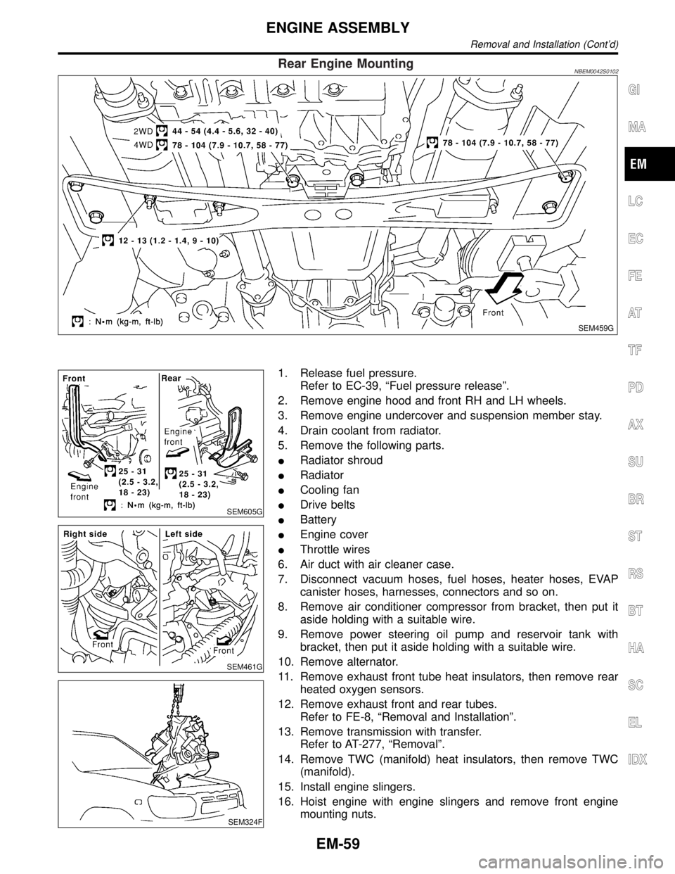
1. Release fuel pressure.
Refer to EC-39, ªFuel pressure releaseº.
2. Remove engine hood and front RH and LH wheels.
3. Remove engine undercover and suspension member stay.
4. Drain coolant from radiator.
5. Remove the following parts.
IRadiator shroud
IRadiator
ICooling fan
IDrive belts
IBattery
IEngine cover
IThrottle wires
6. Air duct with air cleaner case.
7. Disconnect vacuum hoses, fuel hoses, heater hoses, EVAP
canister hoses, harnesses, connectors and so on.
8. Remove air conditioner compressor from bracket, then put it
aside holding with a suitable wire.
9. Remove power steering oil pump and reservoir tank with
bracket, then put it aside holding with a suitable wire.
10. Remove alternator.
11. Remove exhaust front tube heat insulators, then remove rear
heated oxygen sensors.
12. Remove exhaust front and rear tubes.
Refer to FE-8, ªRemoval and Installationº.
13. Remove transmission with transfer.
Refer to AT-277, ªRemovalº.
14. Remove TWC (manifold) heat insulators, then remove TWC
(manifold).
15. Install engine slingers.
16. Hoist engine with engine slingers and remove front engine
mounting nuts.
GI
MA
LC
EC
FE
AT
TF
PD
AX
SU
BR
ST
RS
BT
HA
SC
EL
IDX
ENGINE ASSEMBLY
Removal and Installation (Cont'd)
EM-59