Page 2272 of 2395
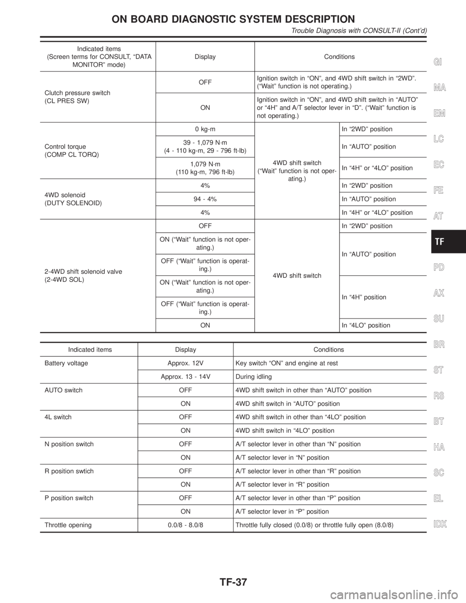
Indicated items
(Screen terms for CONSULT, ªDATA
MONITORº mode)Display Conditions
Clutch pressure switch
(CL PRES SW)OFFIgnition switch in ªONº, and 4WD shift switch in ª2WDº.
(ªWaitº function is not operating.)
ONIgnition switch in ªONº, and 4WD shift switch in ªAUTOº
or ª4Hº and A/T selector lever in ªDº. (ªWaitº function is
not operating.)
Control torque
(COMP CL TORQ)0 kg-m
4WD shift switch
(ªWaitº function is not oper-
ating.)In ª2WDº position
39 - 1,079 N´m
(4 - 110 kg-m, 29 - 796 ft-lb)In ªAUTOº position
1,079 N´m
(110 kg-m, 796 ft-lb)In ª4Hº or ª4LOº position
4WD solenoid
(DUTY SOLENOID)4% In ª2WDº position
94 - 4% In ªAUTOº position
4% In ª4Hº or ª4LOº position
2-4WD shift solenoid valve
(2-4WD SOL)OFF
4WD shift switchIn ª2WDº position
ON (ªWaitº function is not oper-
ating.)
In ªAUTOº position
OFF (ªWaitº function is operat-
ing.)
ON (ªWaitº function is not oper-
ating.)
In ª4Hº position
OFF (ªWaitº function is operat-
ing.)
ON In ª4LOº position
Indicated items Display Conditions
Battery voltage Approx. 12V Key switch ªONº and engine at rest
Approx. 13 - 14V During idling
AUTO switch OFF 4WD shift switch in other than ªAUTOº position
ON 4WD shift switch in ªAUTOº position
4L switch OFF 4WD shift switch in other than ª4LOº position
ON 4WD shift switch in ª4LOº position
N position switch OFF A/T selector lever in other than ªNº position
ON A/T selector lever in ªNº position
R position swtich OFF A/T selector lever in other than ªRº position
ON A/T selector lever in ªRº position
P position switch OFF A/T selector lever in other than ªPº position
ON A/T selector lever in ªPº position
Throttle opening 0.0/8 - 8.0/8 Throttle fully closed (0.0/8) or throttle fully open (8.0/8)
GI
MA
EM
LC
EC
FE
AT
PD
AX
SU
BR
ST
RS
BT
HA
SC
EL
IDX
ON BOARD DIAGNOSTIC SYSTEM DESCRIPTION
Trouble Diagnosis with CONSULT-II (Cont'd)
TF-37
Page 2289 of 2395
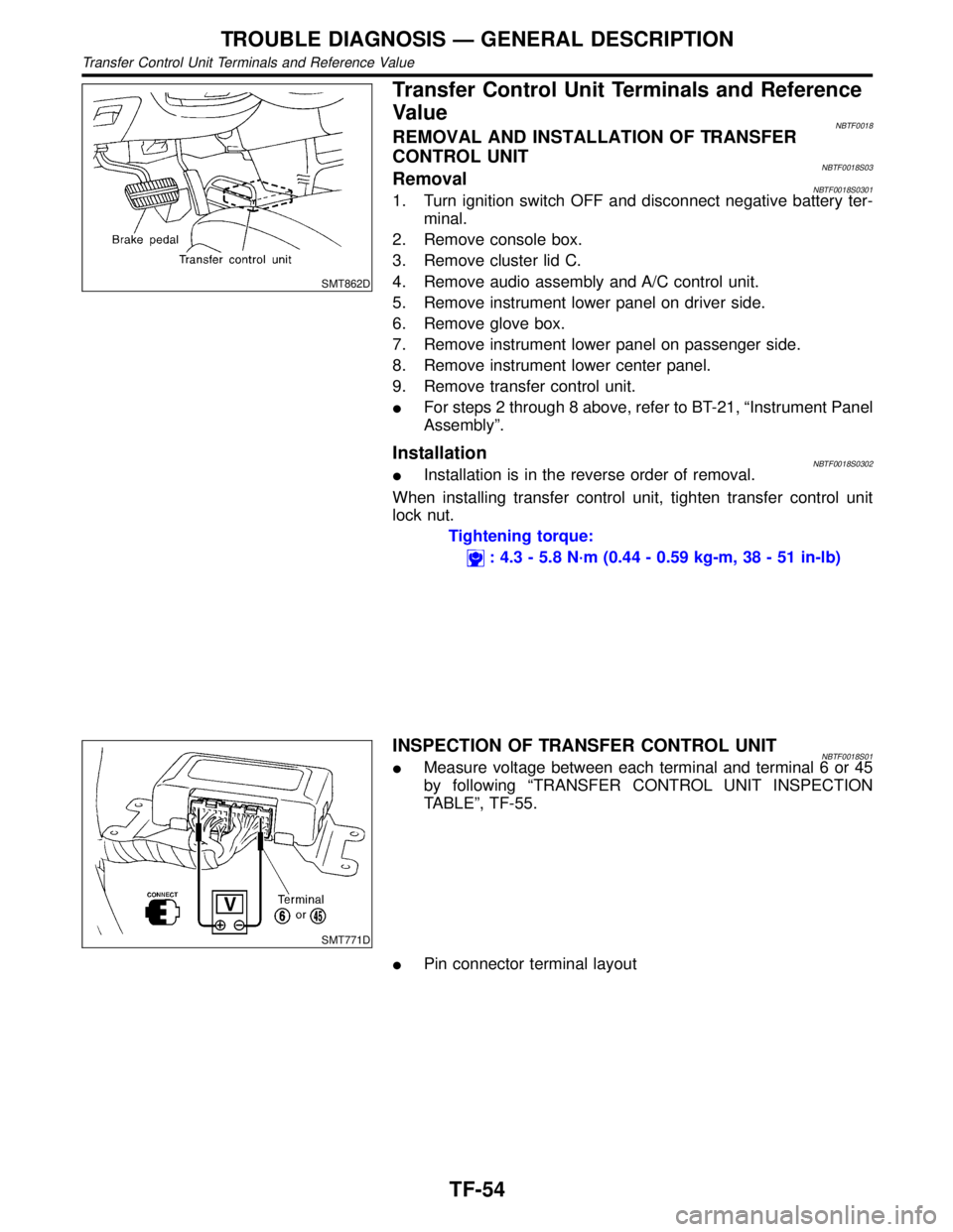
SMT862D
Transfer Control Unit Terminals and Reference
Value
NBTF0018REMOVAL AND INSTALLATION OF TRANSFER
CONTROL UNIT
NBTF0018S03RemovalNBTF0018S03011. Turn ignition switch OFF and disconnect negative battery ter-
minal.
2. Remove console box.
3. Remove cluster lid C.
4. Remove audio assembly and A/C control unit.
5. Remove instrument lower panel on driver side.
6. Remove glove box.
7. Remove instrument lower panel on passenger side.
8. Remove instrument lower center panel.
9. Remove transfer control unit.
IFor steps 2 through 8 above, refer to BT-21, ªInstrument Panel
Assemblyº.
InstallationNBTF0018S0302IInstallation is in the reverse order of removal.
When installing transfer control unit, tighten transfer control unit
lock nut.
Tightening torque:
: 4.3 - 5.8 N´m (0.44 - 0.59 kg-m, 38 - 51 in-lb)
SMT771D
INSPECTION OF TRANSFER CONTROL UNITNBTF0018S01IMeasure voltage between each terminal and terminal 6 or 45
by following ªTRANSFER CONTROL UNIT INSPECTION
TABLEº, TF-55.
IPin connector terminal layout
TROUBLE DIAGNOSIS Ð GENERAL DESCRIPTION
Transfer Control Unit Terminals and Reference Value
TF-54
Page 2351 of 2395
SMT844DB
Replacing Oil SealNBTF0068FRONT CASE OIL SEALNBTF0068S011. Drain transfer fluid.
2. Remove exhaust front tube and heat insulator. Refer to
ªRemovalº, TF-119.
3. Remove front propeller shaft. Refer to PD-6, ªRemoval and
Installationº.
4. Remove companion flange lock nut.
IDo not reuse lock nut.
SMT112D
5. Put a matchmark on top of drive pinion thread. The mark
should be in line with the mark on the companion flange.
IAlways mark top of drive pinion screw using paint.
SMT802C
6. Remove companion flange.
SMT803C
7. Remove front case oil seal.
8. Install front case oil seal.
IBefore installing, apply multi-purpose grease to seal lip.
9. Install companion flange.
SMT845DB
10. Tighten nut to the specified torque.
Refer to TF-121.
11. Install front propeller shaft.
ON-VEHICLE SERVICE
Replacing Oil Seal
TF-116
Page 2354 of 2395
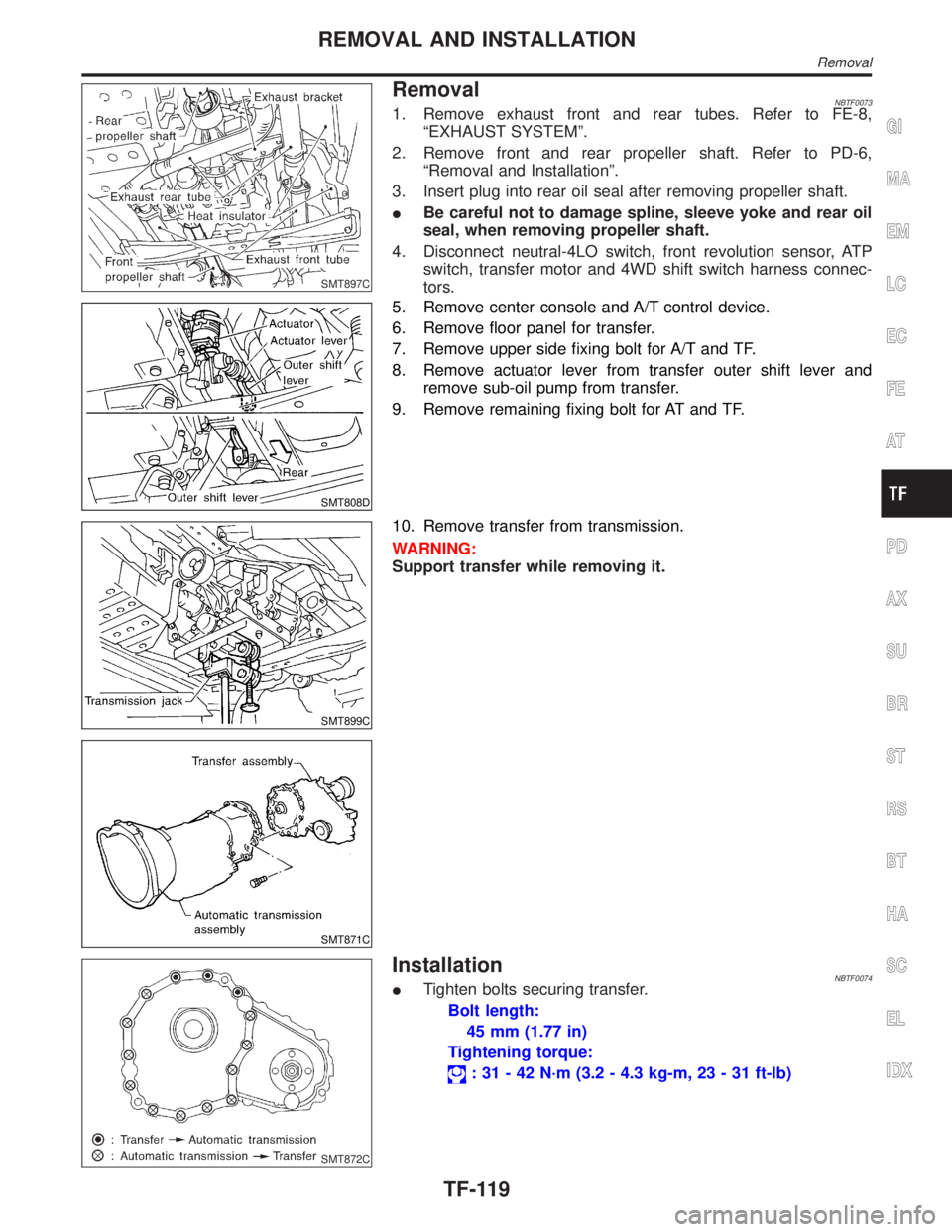
SMT897C
RemovalNBTF00731. Remove exhaust front and rear tubes. Refer to FE-8,
ªEXHAUST SYSTEMº.
2. Remove front and rear propeller shaft. Refer to PD-6,
ªRemoval and Installationº.
3. Insert plug into rear oil seal after removing propeller shaft.
IBe careful not to damage spline, sleeve yoke and rear oil
seal, when removing propeller shaft.
4. Disconnect neutral-4LO switch, front revolution sensor, ATP
switch, transfer motor and 4WD shift switch harness connec-
tors.
SMT808D
5. Remove center console and A/T control device.
6. Remove floor panel for transfer.
7. Remove upper side fixing bolt for A/T and TF.
8. Remove actuator lever from transfer outer shift lever and
remove sub-oil pump from transfer.
9. Remove remaining fixing bolt for AT and TF.
SMT899C
SMT871C
10. Remove transfer from transmission.
WARNING:
Support transfer while removing it.
SMT872C
InstallationNBTF0074ITighten bolts securing transfer.
Bolt length:
45 mm (1.77 in)
Tightening torque:
: 31 - 42 N´m (3.2 - 4.3 kg-m, 23 - 31 ft-lb)
GI
MA
EM
LC
EC
FE
AT
PD
AX
SU
BR
ST
RS
BT
HA
SC
EL
IDX
REMOVAL AND INSTALLATION
Removal
TF-119
Page 2376 of 2395
SMT011D
Front Case
ASSEMBLYNBTF0082Planetary Carrier, Sun Gear and Internal GearNBTF0082S011. Apply ATF to oil seal periphery, and install oil seal so that it is
flush with the end face of front case.
IDo not reuse oil seal.
SMT012D
2. Install internal gear with its groove facing snap ring into front
case. Then secure it with snap ring.
IDo not reuse snap ring.
SMT108D
3. Remove all the liquid gasket on plug bolt and front case. Apply
locking sealant to plug bolt, install it to front case and tighten
it to specified torque.
IWith one crest of plug bolt inserted in the hole, apply liquid
gasket 1215 to the thread.
: 19 - 25 N´m (1.9 - 2.5 kg-m, 14 - 18 ft-lb)
SMT014D
4. Install snap ring to main gear bearing.
IDo not reuse snap rings.
SMT015D
5. Set main gear bearing to front case, then press it.
GI
MA
EM
LC
EC
FE
AT
PD
AX
SU
BR
ST
RS
BT
HA
SC
EL
IDX
ASSEMBLY
Front Case
TF-141
Page 2379 of 2395
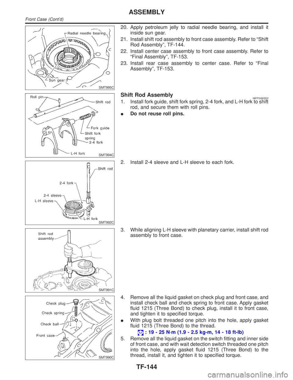
SMT995C
20. Apply petroleum jelly to radial needle bearing, and install it
inside sun gear.
21. Install shift rod assembly to front case assembly. Refer to ªShift
Rod Assemblyº, TF-144.
22. Install center case assembly to front case assembly. Refer to
ªFinal Assemblyº, TF-153.
23. Install rear case assembly to center case. Refer to ªFinal
Assemblyº, TF-153.
SMT994C
Shift Rod AssemblyNBTF0082S021. Install fork guide, shift fork spring, 2-4 fork, and L-H fork to shift
rod, and secure them with roll pins.
IDo not reuse roll pins.
SMT992C
2. Install 2-4 sleeve and L-H sleeve to each fork.
SMT991C
3. While aligning L-H sleeve with planetary carrier, install shift rod
assembly to front case.
SMT990C
4. Remove all the liquid gasket on check plug and front case, and
install check ball and check spring to front case. Apply gasket
fluid 1215 (Three Bond) to check plug, install it to front case,
and tighten it to specified torque.
IWith plug bolt threaded one pitch into the hole, apply gasket
fluid 1215 (Three Bond) to the thread.
: 19 - 25 N´m (1.9 - 2.5 kg-m, 14 - 18 ft-lb)
5. Remove all the liquid gasket on the switch fitting and inner side
of front case, and with wait detection switch threaded one pitch
into the hole, apply gasket fluid 1215 (Three Bond) to the
thread, install it, and tighten it to specified torque.
ASSEMBLY
Front Case (Cont'd)
TF-144
Page 2383 of 2395
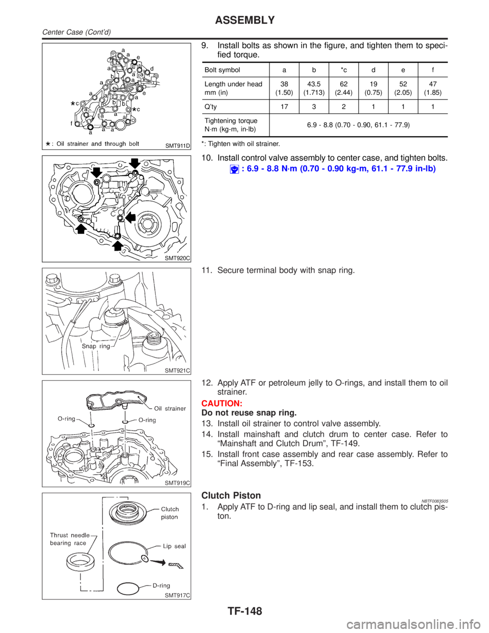
SMT911D
9. Install bolts as shown in the figure, and tighten them to speci-
fied torque.
Bolt symbol a b *c d e f
Length under head
mm (in)38
(1.50)43.5
(1.713)62
(2.44)19
(0.75)52
(2.05)47
(1.85)
Q'ty 1732111
Tightening torque
N´m (kg-m, in-lb)6.9 - 8.8 (0.70 - 0.90, 61.1 - 77.9)
*: Tighten with oil strainer.
SMT920C
10. Install control valve assembly to center case, and tighten bolts.
: 6.9 - 8.8 N´m (0.70 - 0.90 kg-m, 61.1 - 77.9 in-lb)
SMT921C
11. Secure terminal body with snap ring.
SMT919C
12. Apply ATF or petroleum jelly to O-rings, and install them to oil
strainer.
CAUTION:
Do not reuse snap ring.
13. Install oil strainer to control valve assembly.
14. Install mainshaft and clutch drum to center case. Refer to
ªMainshaft and Clutch Drumº, TF-149.
15. Install front case assembly and rear case assembly. Refer to
ªFinal Assemblyº, TF-153.
SMT917C
Clutch PistonNBTF0083S051. Apply ATF to D-ring and lip seal, and install them to clutch pis-
ton.
ASSEMBLY
Center Case (Cont'd)
TF-148
Page 2389 of 2395
SMT894C
4. Make sure the two claws of oil gutter are securely attached to
slots in center case.
SMT895C
5. With the claws of oil gutter held by a finger, install center case
assembly to front case assembly.
CAUTION:
Pay careful attention so that mainshaft end does not damage
radial needle bearing in sun gear assembly.
6. Tap center case lightly with a rubber hammer or the like and
press-fit front drive shaft bearing into front case.
SMT896C
7. Make sure oil gutter rear end protrudes from point ªAº in the
figure.
8. Tighten bolts to specified torque.
: 41 - 48 N´m (4.2 - 4.9 kg-m, 30 - 35 ft-lb)
IBe sure to install air breather hose clamp, connector
bracket and harness clip.
SMT883C
9. Fit double-flat end of oil pump shaft into slot of main oil pump
and install it.
NOTE:
When oil pump shaft is rotated slightly, it drops into position where
both parts fit.
SMT884C
10. Install stem bleeder to center case.
ASSEMBLY
Final Assembly (Cont'd)
TF-154