2001 INFINITI QX4 torque
[x] Cancel search: torquePage 2227 of 2395
INSPECTION=NBSU0015Transverse LinkNBSU0015S01ICheck transverse link for damage, cracks and deformation.
Replace it if necessary.
ICheck rubber bushing for damage, cracks and deformation.
Replace transverse link if necessary.
SFA858AA
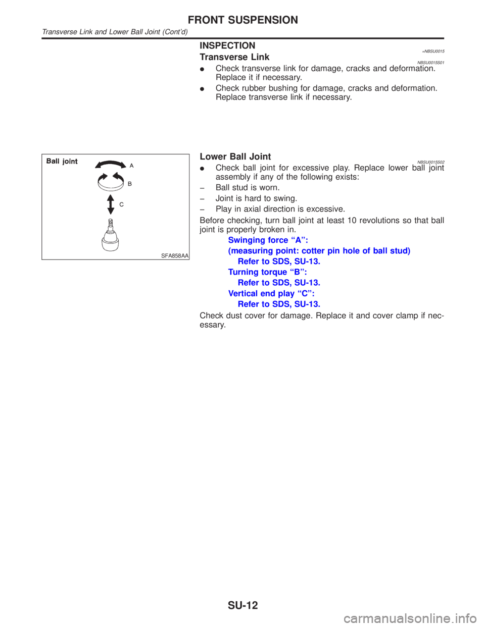
Lower Ball JointNBSU0015S02ICheck ball joint for excessive play. Replace lower ball joint
assembly if any of the following exists:
þ Ball stud is worn.
þ Joint is hard to swing.
þ Play in axial direction is excessive.
Before checking, turn ball joint at least 10 revolutions so that ball
joint is properly broken in.
Swinging force ªAº:
(measuring point: cotter pin hole of ball stud)
Refer to SDS, SU-13.
Turning torque ªBº:
Refer to SDS, SU-13.
Vertical end play ªCº:
Refer to SDS, SU-13.
Check dust cover for damage. Replace it and cover clamp if nec-
essary.
FRONT SUSPENSION
Transverse Link and Lower Ball Joint (Cont'd)
SU-12
Page 2228 of 2395
Service Data and Specifications (SDS)
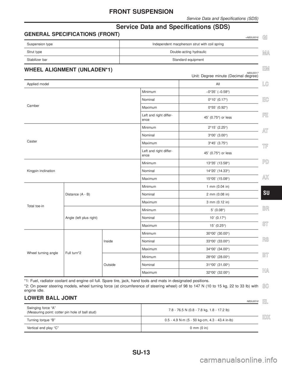
GENERAL SPECIFICATIONS (FRONT)=NBSU0016
Suspension type Independent macpherson strut with coil spring
Strut typeDouble-acting hydraulic
Stabilizer barStandard equipment
WHEEL ALIGNMENT (UNLADEN*1)NBSU0017Unit: Degree minute (Decimal degree)
Applied modelAll
CamberMinimum þ0É35¢(þ0.58É)
Nominal 0É10¢(0.17É)
Maximum 0É55¢(0.92É)
Left and right differ-
ence45¢(0.75É) or less
CasterMinimum 2É15¢(2.25É)
Nominal 3É00¢(3.00É)
Maximum 3É45¢(3.75É)
Left and right differ-
ence45¢(0.75É) or less
Kingpin inclinationMinimum 13É35¢(13.58É)
Nominal 14É20¢(14.33É)
Maximum 15É05¢(15.08É)
Total toe-inDistance (A - B)Minimum 1 mm (0.04 in)
Nominal 2 mm (0.08 in)
Maximum 3 mm (0.12 in)
Angle (left plus right)Minimum 5¢(0.08É)
Nominal 10¢(0.17É)
Maximum 15¢(0.25É)
Wheel turning angle Full turn*2InsideMinimum 30É00¢(30.00É)
Nominal 33É00¢(33.00É)
Maximum 34É00¢(34.00É)
OutsideMinimum 28É00¢(28.00É)
Nominal 31É00¢(31.00É)
Maximum 32É00¢(32.00É)
*1: Fuel, radiator coolant and engine oil full. Spare tire, jack, hand tools and mats in designated positions.
*2: On power steering models, wheel turning force (at circumference of steering wheel) of 98 to 147 N (10 to 15 kg, 22 to 33 lb) with
engine idle.
LOWER BALL JOINTNBSU0018
Swinging force ªAº
(Measuring point: cotter pin hole of ball stud)7.8 - 76.5 N (0.8 - 7.8 kg, 1.8 - 17.2 lb)
Turning torque ªBº 0.5 - 4.9 N´m (5 - 50 kg-cm, 4.3 - 43.4 in-lb)
Vertical end play ªCº0mm(0in)
GI
MA
EM
LC
EC
FE
AT
TF
PD
AX
BR
ST
RS
BT
HA
SC
EL
IDX
FRONT SUSPENSION
Service Data and Specifications (SDS)
SU-13
Page 2230 of 2395
SBR686C
Precautions
PRECAUTIONSNBSU0021IWhen installing rubber parts, final tightening must be car-
ried out under unladen condition* with tires on ground.
*Fuel, radiator coolant and engine oil full. Spare tire, jack,
hand tools and mats in designated positions.
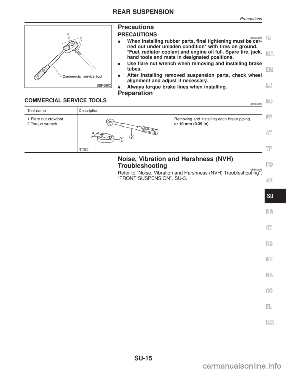
IUse flare nut wrench when removing and installing brake
tubes.
IAfter installing removed suspension parts, check wheel
alignment and adjust if necessary.
IAlways torque brake lines when installing.
Preparation
COMMERCIAL SERVICE TOOLSNBSU0023
Tool name Description
1 Flare nut crowfoot
2 Torque wrench
NT360
Removing and installing each brake piping
a: 10 mm (0.39 in)
Noise, Vibration and Harshness (NVH)
Troubleshooting
NBSU0036Refer to ªNoise, Vibration and Harshness (NVH) Troubleshootingº,
ªFRONT SUSPENSIONº, SU-3.
GI
MA
EM
LC
EC
FE
AT
TF
PD
AX
BR
ST
RS
BT
HA
SC
EL
IDX
REAR SUSPENSION
Precautions
SU-15
Page 2231 of 2395
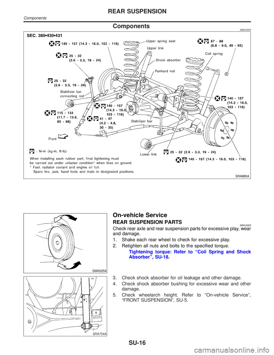
ComponentsNBSU0024
SRA880A
SMA525A
On-vehicle Service
REAR SUSPENSION PARTSNBSU0025Check rear axle and rear suspension parts for excessive play, wear
and damage.
1. Shake each rear wheel to check for excessive play.
2. Retighten all nuts and bolts to the specified torque.
Tightening torque: Refer to ªCoil Spring and Shock
Absorberº, SU-18.
SRA754A
3. Check shock absorber for oil leakage and other damage.
4. Check shock absorber bushing for excessive wear and other
damage.
5. Check wheelarch height. Refer to ªOn-vehicle Serviceº,
ªFRONT SUSPENSIONº, SU-5.
REAR SUSPENSION
Components
SU-16
Page 2239 of 2395

MEF040DB
IBefore replacing Transfer control unit, perform Transfer
control unit input/output signal inspection and make sure
whether Transfer control unit functions properly or not.
(See page TF-55.)
Service NoticeNBTF00021) Before proceeding with disassembly, thoroughly clean the outside of the all-mode 4WD transfer. It is
important to prevent the internal parts from becoming contaminated by dirt or other foreign matter.
2) Disassembly should be done in a clean work area.
3) Use lint-free cloth or towels for wiping parts clean. Common shop rags can leave fibers that could inter-
fere with the operation of the all-mode 4WD transfer.
4) Place disassembled parts in order for easier and proper assembly.
5) All parts should be carefully cleaned with a general purpose, non-flammable solvent before inspection or
reassembly.
6) Gaskets, seals and O-rings should be replaced any time the all-mode 4WD transfer is disassembled.
7) It is very important to perform functional tests whenever they are indicated.
8) The valve body contains precision parts and requires extreme care when parts are removed and serviced.
Place removed parts in a parts rack in order to replace them in correct positions and sequences. Care will
also prevent springs and small parts from becoming scattered or lost.
9) Properly installed valves, sleeves, plugs, etc. will slide along bores in valve body under their own weight.
10) Before assembly, apply a coat of recommended ATF to all parts. Apply petroleum jelly to protect O-rings
and seals, and to hold bearings and washers in place during assembly. Do not use grease.
11) Extreme care should be taken to avoid damage to O-rings, seals and gaskets when assembling.
12) After overhaul, refill the transfer with new ATF.
13) When the all-mode 4WD transfer drain plug is removed, only some of the fluid is drained. Old all-mode
4WD transfer fluid will remain in torque converter and ATF cooling system. Always follow the procedures,
MA-22, ªChanging All-mode 4WD Transfer Fluidº.
Wiring Diagrams and Trouble DiagnosisNBTF0003When you read wiring diagrams, refer to the following:
IGI-11, ªHOW TO READ WIRING DIAGRAMSº
IEL-9, ªPOWER SUPPLY ROUTINGº
When you perform trouble diagnosis, refer to the following:
IGI-35, ªHOW TO FOLLOW TEST GROUPS IN TROUBLE DIAGNOSISº
IGI-24, ªHOW TO PERFORM EFFICIENT DIAGNOSIS FOR AN ELECTRICAL INCIDENTº
PRECAUTIONS
Precautions (Cont'd)
TF-4
Page 2250 of 2395
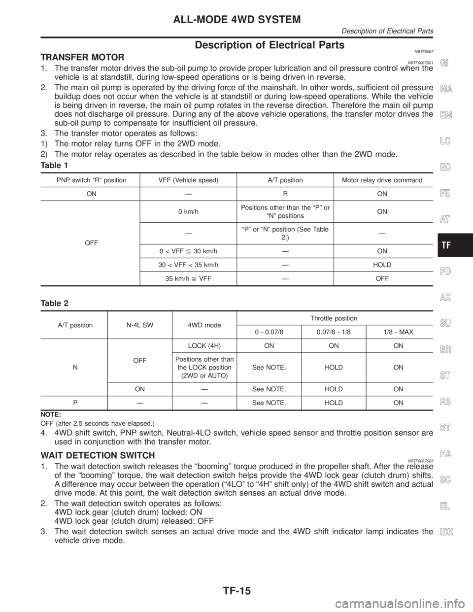
Description of Electrical PartsNBTF0067TRANSFER MOTORNBTF0067S011. The transfer motor drives the sub-oil pump to provide proper lubrication and oil pressure control when the
vehicle is at standstill, during low-speed operations or is being driven in reverse.
2. The main oil pump is operated by the driving force of the mainshaft. In other words, sufficient oil pressure
buildup does not occur when the vehicle is at standstill or during low-speed operations. While the vehicle
is being driven in reverse, the main oil pump rotates in the reverse direction. Therefore the main oil pump
does not discharge oil pressure. During any of the above vehicle operations, the transfer motor drives the
sub-oil pump to compensate for insufficient oil pressure.
3. The transfer motor operates as follows:
1) The motor relay turns OFF in the 2WD mode.
2) The motor relay operates as described in the table below in modes other than the 2WD mode.
Table 1
PNP switch ªRº position VFF (Vehicle speed) A/T position Motor relay drive command
ON Ð R ON
OFF0 km/hPositions other than the ªPº or
ªNº positionsON
ЪPº or ªNº position (See Table
2.)Ð
0 < VFF%30 km/h Ð ON
30 < VFF < 35 km/h Ð HOLD
35 km/h%VFF Ð OFF
Table 2
A/T position N-4L SW 4WD modeThrottle position
0 - 0.07/8 0.07/8 - 1/8 1/8 - MAX
NOFFLOCK (4H) ON ON ON
Positions other than
the LOCK position
(2WD or AUTO)See NOTE. HOLD ON
ON Ð See NOTE. HOLD ON
P Ð Ð See NOTE. HOLD ON
NOTE:
OFF (after 2.5 seconds have elapsed.)
4. 4WD shift switch, PNP switch, Neutral-4LO switch, vehicle speed sensor and throttle position sensor are
used in conjunction with the transfer motor.
WAIT DETECTION SWITCHNBTF0067S021. The wait detection switch releases the ªboomingº torque produced in the propeller shaft. After the release
of the ªboomingº torque, the wait detection switch helps provide the 4WD lock gear (clutch drum) shifts.
A difference may occur between the operation (ª4LOº to ª4Hº shift only) of the 4WD shift switch and actual
drive mode. At this point, the wait detection switch senses an actual drive mode.
2. The wait detection switch operates as follows:
4WD lock gear (clutch drum) locked: ON
4WD lock gear (clutch drum) released: OFF
3. The wait detection switch senses an actual drive mode and the 4WD shift indicator lamp indicates the
vehicle drive mode.
GI
MA
EM
LC
EC
FE
AT
PD
AX
SU
BR
ST
RS
BT
HA
SC
EL
IDX
ALL-MODE 4WD SYSTEM
Description of Electrical Parts
TF-15
Page 2251 of 2395
2-4WD SHIFT SOLENOID VALVENBTF0067S03The 2-4WD shift solenoid valve operates to apply oil pressure to the wet, multiplate clutch, depending on the
drive mode. The driving force is transmitted to the front wheels through the clutch so the vehicle is set in the
4WD mode. Setting the vehicle in the 2WD mode requires no pressure buildup. In other words, pressure force
applied to the wet, multiplate clutch becomes zero.
LINE PRESSURE SWITCHNBTF0067S041. With the transfer system design, control of the oil pressure provides the transmission of drive torque to
the front wheels. The main pressure to control the oil pressure is referred to as the line pressure.
The line pressure switch determines whether or not adequate line pressure has built up under different
operating conditions.
2. The line pressure switch turns ON when line pressure is produced.
3. The line pressure switch senses line pressure abnormalities and turns the 4WD warning lamp ON.
ALL-MODE 4WD SYSTEM
Description of Electrical Parts (Cont'd)
TF-16
Page 2269 of 2395
![INFINITI QX4 2001 Factory Service Manual SMT963D
12. Monitored data are displayed.
DATA MONITOR ITEMSNBTF0012S04q: StandardH: Option
Item [Unit]Monitor item
Remarks
ECU input
signalsMain sig-
nalsItem menu
selection
Revolution sensor-front [ INFINITI QX4 2001 Factory Service Manual SMT963D
12. Monitored data are displayed.
DATA MONITOR ITEMSNBTF0012S04q: StandardH: Option
Item [Unit]Monitor item
Remarks
ECU input
signalsMain sig-
nalsItem menu
selection
Revolution sensor-front [](/manual-img/42/57027/w960_57027-2268.png)
SMT963D
12. Monitored data are displayed.
DATA MONITOR ITEMSNBTF0012S04q: StandardH: Option
Item [Unit]Monitor item
Remarks
ECU input
signalsMain sig-
nalsItem menu
selection
Revolution sensor-front [km/h (MPH)]qHRevolution sensor installed on T/F
Revolution sensor-rear [km/h (MPH)]qHVehicle speed sensor´A/T
Engine speed [rpm]qH
Throttle position sensor [V]qH
Transfer fluid temperature sensor [V]qH
Battery voltage [V]qH
2WD switch [ON-OFF]qH2WD switch of 4WD shift switch
AUTO switch [ON-OFF]qHAUTO switch of 4WD shift switch
Lock switch [ON-OFF]qH4H switch of 4WD shift switch
4L switch [ON-OFF]qH4LO switch of 4WD shift switch
N position switch TF [ON-OFF]qHN position switch of transfer
Line pressure switch [ON-OFF]qHLine pressure switch
Clutch pressure switch [ON-OFF]qHClutch pressure switch
ATP switch [ON-OFF]qH
N position switch [ON-OFF]qHªNº position on A/T PNP switch
R position switch [ON-OFF]qHªRº position on A/T PNP switch
P position switch [ON-OFF]qHªPº position on A/T PNP switch
Closed throttle position switch
[ON/OFF]qHIdle contact of throttle position switch
ABS operation switch [ON-OFF]qHABS operation switch
Wait detection switch [ON-OFF]qH
Throttle openingqHThrottle opening recognized by transfer control
unit
4WD-modeqH4WD-mode recognized by transfer control unit
(2W, AUTO, 4H & 4LO)
Vehicle speed comp [km/h (MPH)]qHVehicle speed recognized by transfer control
unit
*Control torque [N´m (kg-m, ft-lb)]qHCalculated torque recognized by transfer control
unit
ON BOARD DIAGNOSTIC SYSTEM DESCRIPTION
Trouble Diagnosis with CONSULT-II (Cont'd)
TF-34