2001 DODGE TOWN AND COUNTRY battery
[x] Cancel search: batteryPage 1487 of 2321
(4) Install the power steering fluid pressure line
into the pressure output fitting of the power steering
pump (Fig. 11). Tighten the pressure line to pump fit-
ting tube nut to a torque of 31 N´m (275 in. lbs.).
(5) Install the power steering fluid low-pressure
return hose on the power steering pump low pressure
fitting (Fig. 11).Be sure hose clamps are prop-
erly reinstalled.
(6) Raise the vehicle.
(7) Install the routing clip on the engine for the
pressure hose (Fig. 10).
(8) Tighten the pump thru-bolt (Fig. 9). Tighten to
54 N´m (40 ft. lbs.) torque.
(9) Install the serpentine drive belt (Refer to 7 -
COOLING/ACCESSORY DRIVE/DRIVE BELTS -
INSTALLATION).
(10) Install the drive belt splash shield.
(11) Lower the vehicle.
(12) Install the wiper module (unit)(Refer to 8 -
ELECTRICAL/WIPERS/WASHERS/WIPER MOD-
ULE - INSTALLATION).
(13) Connect the negative battery cable on the
negative battery post.
(14) Fill and bleed the power steering system
using the Power Steering Pump Initial Operation
Procedure (Refer to 19 - STEERING/PUMP - STAN-
DARD PROCEDURE).
(15) Inspect for leaks.
SPECIAL TOOLS
POWER STEERING PUMP
FLUID
STANDARD PROCEDURE - POWER STEERING
FLUID LEVEL CHECKING
WARNING: FLUID LEVEL SHOULD BE CHECKED
WITH THE ENGINE OFF TO PREVENT INJURY
FROM MOVING PARTS.
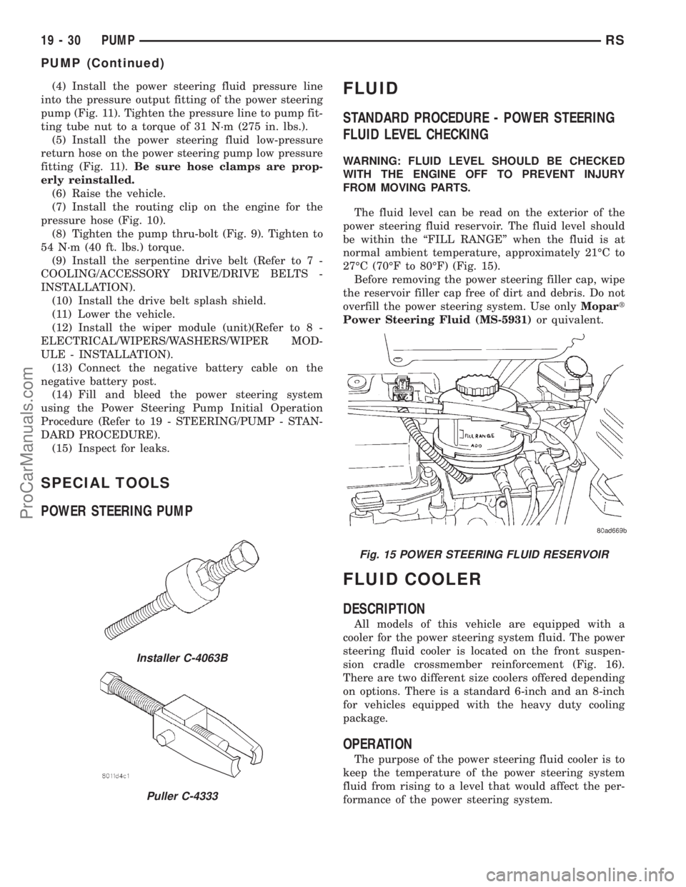
The fluid level can be read on the exterior of the
power steering fluid reservoir. The fluid level should
be within the ªFILL RANGEº when the fluid is at
normal ambient temperature, approximately 21ÉC to
27ÉC (70ÉF to 80ÉF) (Fig. 15).
Before removing the power steering filler cap, wipe
the reservoir filler cap free of dirt and debris. Do not
overfill the power steering system. Use onlyMopart
Power Steering Fluid (MS-5931)or quivalent.
FLUID COOLER
DESCRIPTION
All models of this vehicle are equipped with a
cooler for the power steering system fluid. The power
steering fluid cooler is located on the front suspen-
sion cradle crossmember reinforcement (Fig. 16).
There are two different size coolers offered depending
on options. There is a standard 6-inch and an 8-inch
for vehicles equipped with the heavy duty cooling
package.
OPERATION
The purpose of the power steering fluid cooler is to
keep the temperature of the power steering system
fluid from rising to a level that would affect the per-
formance of the power steering system.
Installer C-4063B
Puller C-4333
Fig. 15 POWER STEERING FLUID RESERVOIR
19 - 30 PUMPRS
PUMP (Continued)
ProCarManuals.com
Page 1495 of 2321
PUMP
TABLE OF CONTENTS
page page
PUMP
DESCRIPTION............................6
REMOVAL...............................6
INSTALLATION............................6RESERVOIR
DESCRIPTION............................7
REMOVAL...............................7
INSTALLATION............................7
PUMP
DESCRIPTION - PUMP (2.5L DIESEL)
Hydraulic pressure for the operation of the power
steering gear is provided by a belt driven power
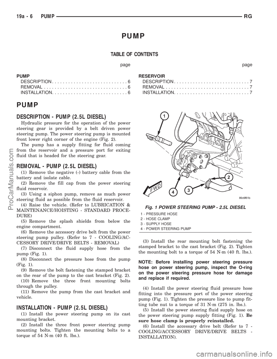
steering pump. The power steering pump is mounted
front lower right corner of the engine (Fig. 2).
The pump has a supply fitting for fluid coming
from the reservoir and a pressure port for exiting
fluid that is headed for the steering gear.
REMOVAL - PUMP (2.5L DIESEL)
(1) Remove the negative (-) battery cable from the
battery and isolate cable.
(2) Remove the fill cap from the power steering
fluid reservoir.
(3) Using a siphon pump, remove as much power
steering fluid as possible from the fluid reservoir.
(4) Raise the vehicle. (Refer to LUBRICATION &
MAINTENANCE/HOISTING - STANDARD PROCE-
DURE)
(5) Remove the splash shields from below the
engine compartment.
(6) Remove the accessory drive belt from the power
steering pump pulley. (Refer to 7 - COOLING/AC-
CESSORY DRIVE/DRIVE BELTS - REMOVAL)
(7) Disconnect the fluid supply hose from the
pump (Fig. 1).
(8) Disconnect the pressure hose from the pump
(Fig. 1).
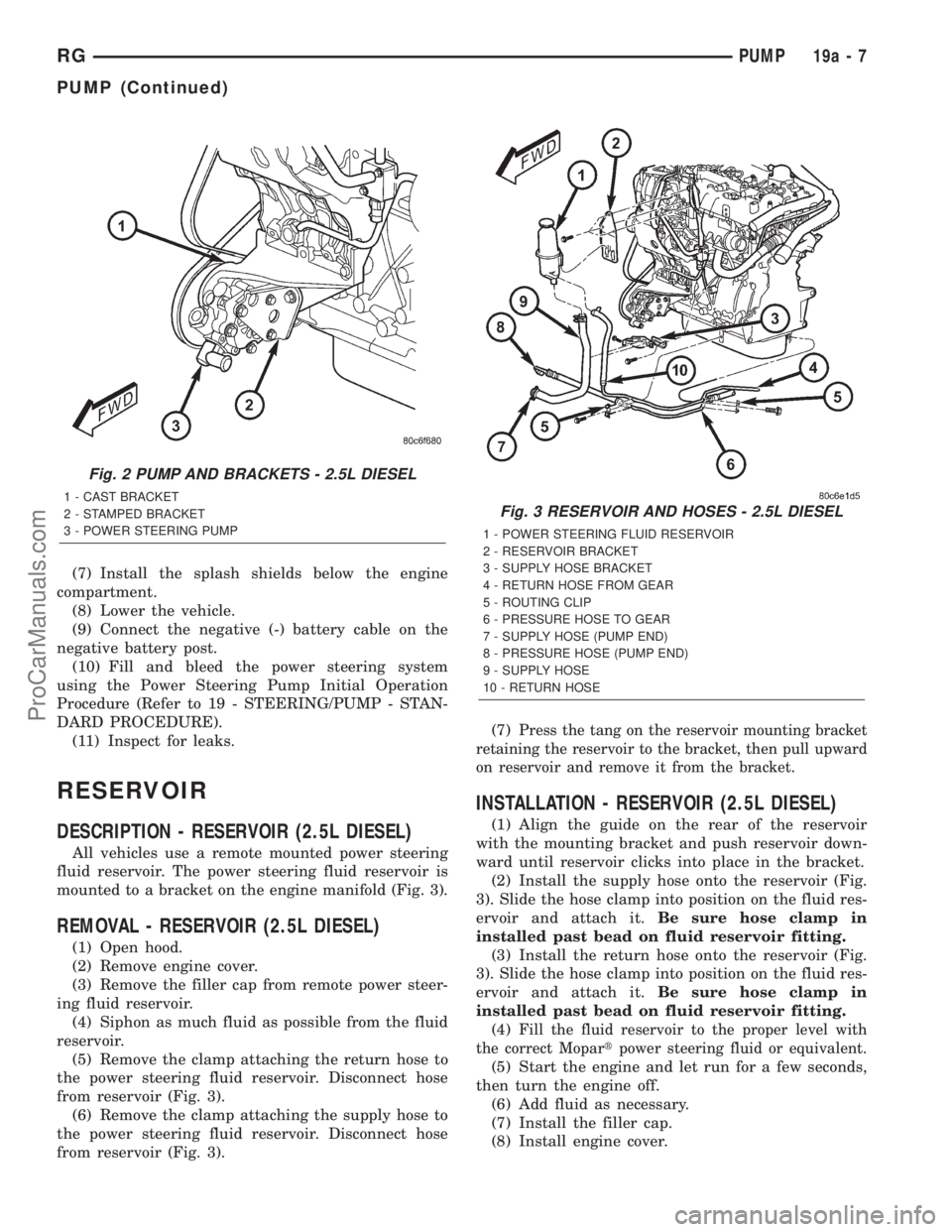
(9) Remove the bolt fastening the stamped bracket
on the rear of the pump to the cast bracket (Fig. 2).
(10) Remove the three front mounting bolts
through the pulley.
(11) Remove the pump from the cast bracket and
vehicle.
INSTALLATION - PUMP (2.5L DIESEL)
(1) Install the power steering pump on its cast
mounting bracket.
(2) Install the three front power steering pump
mounting bolts. Tighten the mounting bolts to a
torque of 54 N´m (40 ft. lbs.).(3) Install the rear mounting bolt fastening the
stamped bracket to the cast bracket (Fig. 2). Tighten
the mounting bolt to a torque of 54 N´m (40 ft. lbs.).
NOTE: Before installing power steering pressure
hose on power steering pump, inspect the O-ring
on the power steering pressure hose for damage
and replace if required.
(4) Install the power steering fluid pressure hose
fitting into the pressure port of the power steering
pump (Fig. 1). Tighten the pressure line to pump fit-
ting tube nut to a torque of 31 N´m (275 in. lbs.).
(5) Install the power steering fluid supply hose on
the power steering pump supply fitting (Fig. 1).Be
sure hose clamp is properly reinstalled.
(6) Install the accessary drive belt (Refer to 7 -
COOLING/ACCESSORY DRIVE/DRIVE BELTS -
INSTALLATION).
Fig. 1 POWER STEERING PUMP - 2.5L DIESEL
1 - PRESSURE HOSE
2 - HOSE CLAMP
3 - SUPPLY HOSE
4 - POWER STEERING PUMP
19a - 6 PUMPRG
ProCarManuals.com
Page 1496 of 2321
(7) Install the splash shields below the engine
compartment.
(8) Lower the vehicle.
(9) Connect the negative (-) battery cable on the
negative battery post.
(10) Fill and bleed the power steering system
using the Power Steering Pump Initial Operation
Procedure (Refer to 19 - STEERING/PUMP - STAN-
DARD PROCEDURE).
(11) Inspect for leaks.
RESERVOIR
DESCRIPTION - RESERVOIR (2.5L DIESEL)
All vehicles use a remote mounted power steering
fluid reservoir. The power steering fluid reservoir is
mounted to a bracket on the engine manifold (Fig. 3).
REMOVAL - RESERVOIR (2.5L DIESEL)
(1) Open hood.
(2) Remove engine cover.
(3) Remove the filler cap from remote power steer-
ing fluid reservoir.
(4) Siphon as much fluid as possible from the fluid
reservoir.
(5) Remove the clamp attaching the return hose to
the power steering fluid reservoir. Disconnect hose
from reservoir (Fig. 3).
(6) Remove the clamp attaching the supply hose to
the power steering fluid reservoir. Disconnect hose
from reservoir (Fig. 3).(7)
Press the tang on the reservoir mounting bracket
retaining the reservoir to the bracket, then pull upward
on reservoir and remove it from the bracket.
INSTALLATION - RESERVOIR (2.5L DIESEL)
(1) Align the guide on the rear of the reservoir
with the mounting bracket and push reservoir down-
ward until reservoir clicks into place in the bracket.
(2) Install the supply hose onto the reservoir (Fig.
3). Slide the hose clamp into position on the fluid res-
ervoir and attach it.Be sure hose clamp in
installed past bead on fluid reservoir fitting.
(3) Install the return hose onto the reservoir (Fig.
3). Slide the hose clamp into position on the fluid res-
ervoir and attach it.Be sure hose clamp in
installed past bead on fluid reservoir fitting.
(4)
Fill the fluid reservoir to the proper level with
the correct Mopartpower steering fluid or equivalent.
(5) Start the engine and let run for a few seconds,
then turn the engine off.
(6) Add fluid as necessary.
(7) Install the filler cap.
(8) Install engine cover.
Fig. 2 PUMP AND BRACKETS - 2.5L DIESEL
1 - CAST BRACKET
2 - STAMPED BRACKET
3 - POWER STEERING PUMP
Fig. 3 RESERVOIR AND HOSES - 2.5L DIESEL
1 - POWER STEERING FLUID RESERVOIR
2 - RESERVOIR BRACKET
3 - SUPPLY HOSE BRACKET
4 - RETURN HOSE FROM GEAR
5 - ROUTING CLIP
6 - PRESSURE HOSE TO GEAR
7 - SUPPLY HOSE (PUMP END)
8 - PRESSURE HOSE (PUMP END)
9 - SUPPLY HOSE
10 - RETURN HOSE
RGPUMP19a-7
PUMP (Continued)
ProCarManuals.com
Page 1533 of 2321
KICKDOWN SERVO (FRONT)
Direct air pressure into KICKDOWN SERVO ON
passage. Operation of servo is indicated by a tighten-
ing of front band. Spring tension on servo piston
should release the band.
LOW AND REVERSE SERVO (REAR)
Direct air pressure into LOW-REVERSE SERVO
APPLY passage. Operation of servo is indicated by a
tightening of rear band. Spring tension on servo pis-
ton should release the band.
If clutches and servos operate properly, no upshift
indicates that a malfunction exists in the valve body.
STANDARD PROCEDURE - ALUMINUM
THREAD REPAIR
Damaged or worn threads in the aluminum trans-
axle case and valve body can be repaired by the use
of Heli-Coils, or equivalent. This repair consists of
drilling out the worn-out damaged threads. Then tap-
ping the hole with a Heli-Coil tap, or equivalent, and
installing a Heli-Coil insert, or equivalent, into the
hole. This brings the hole back to its original thread
size.
Heli-Coil, or equivalent, tools and inserts are
readily available from most automotive parts suppli-
ers.
REMOVAL
(1) Disconnect battery negative cable.
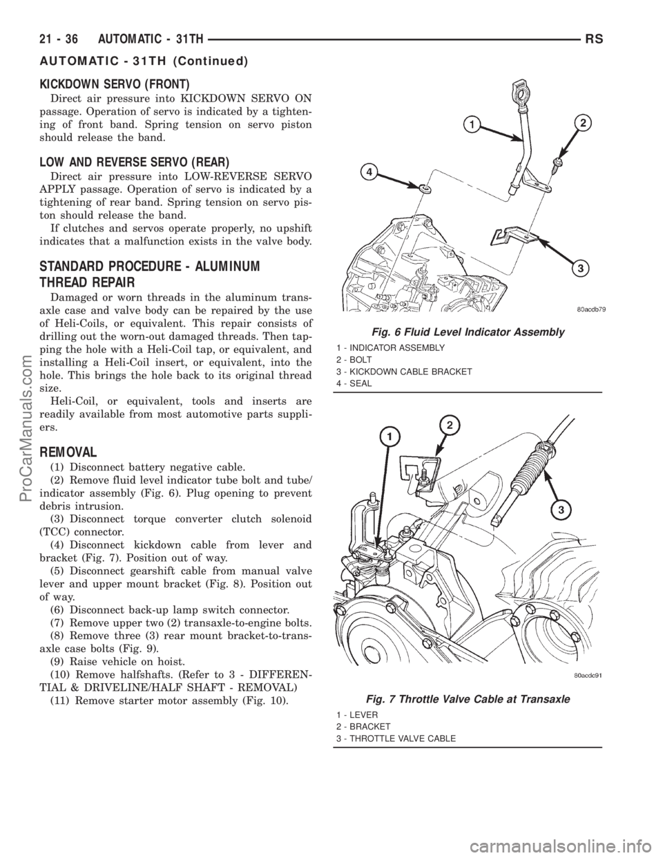
(2) Remove fluid level indicator tube bolt and tube/
indicator assembly (Fig. 6). Plug opening to prevent
debris intrusion.
(3) Disconnect torque converter clutch solenoid
(TCC) connector.
(4) Disconnect kickdown cable from lever and
bracket (Fig. 7). Position out of way.
(5) Disconnect gearshift cable from manual valve
lever and upper mount bracket (Fig. 8). Position out
of way.
(6) Disconnect back-up lamp switch connector.
(7) Remove upper two (2) transaxle-to-engine bolts.
(8) Remove three (3) rear mount bracket-to-trans-
axle case bolts (Fig. 9).
(9) Raise vehicle on hoist.
(10) Remove halfshafts. (Refer to 3 - DIFFEREN-
TIAL & DRIVELINE/HALF SHAFT - REMOVAL)
(11) Remove starter motor assembly (Fig. 10).
Fig. 6 Fluid Level Indicator Assembly
1 - INDICATOR ASSEMBLY
2 - BOLT
3 - KICKDOWN CABLE BRACKET
4 - SEAL
Fig. 7 Throttle Valve Cable at Transaxle
1 - LEVER
2 - BRACKET
3 - THROTTLE VALVE CABLE
21 - 36 AUTOMATIC - 31THRS
AUTOMATIC - 31TH (Continued)
ProCarManuals.com
Page 1559 of 2321
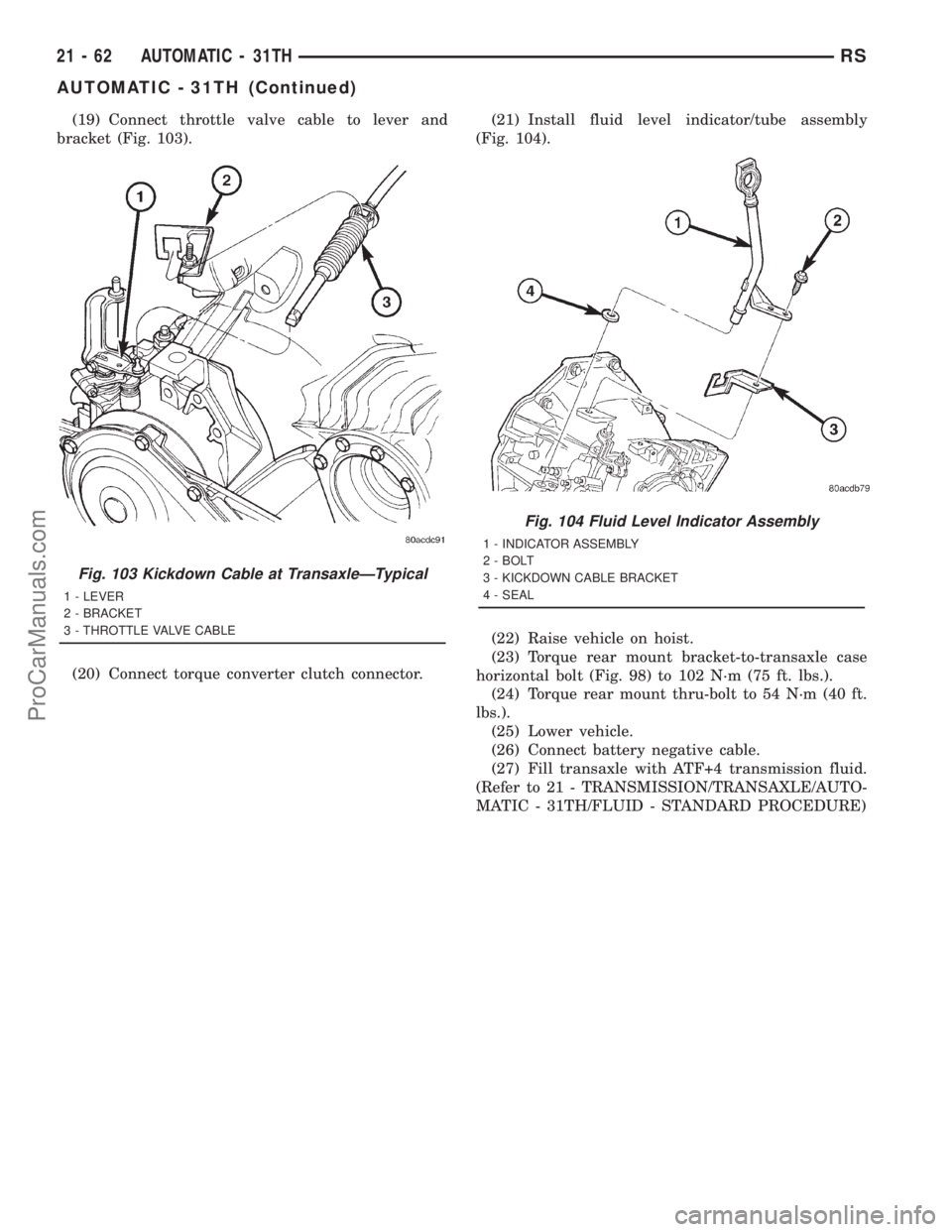
(19) Connect throttle valve cable to lever and
bracket (Fig. 103).
(20) Connect torque converter clutch connector.(21) Install fluid level indicator/tube assembly
(Fig. 104).
(22) Raise vehicle on hoist.
(23) Torque rear mount bracket-to-transaxle case
horizontal bolt (Fig. 98) to 102 N´m (75 ft. lbs.).
(24) Torque rear mount thru-bolt to 54 N´m (40 ft.
lbs.).
(25) Lower vehicle.
(26) Connect battery negative cable.
(27) Fill transaxle with ATF+4 transmission fluid.
(Refer to 21 - TRANSMISSION/TRANSAXLE/AUTO-
MATIC - 31TH/FLUID - STANDARD PROCEDURE)
Fig. 103 Kickdown Cable at TransaxleÐTypical
1 - LEVER
2 - BRACKET
3 - THROTTLE VALVE CABLE
Fig. 104 Fluid Level Indicator Assembly
1 - INDICATOR ASSEMBLY
2 - BOLT
3 - KICKDOWN CABLE BRACKET
4 - SEAL
21 - 62 AUTOMATIC - 31THRS
AUTOMATIC - 31TH (Continued)
ProCarManuals.com
Page 1576 of 2321
BANDS
KICKDOWN (FRONT) BAND
DESCRIPTION
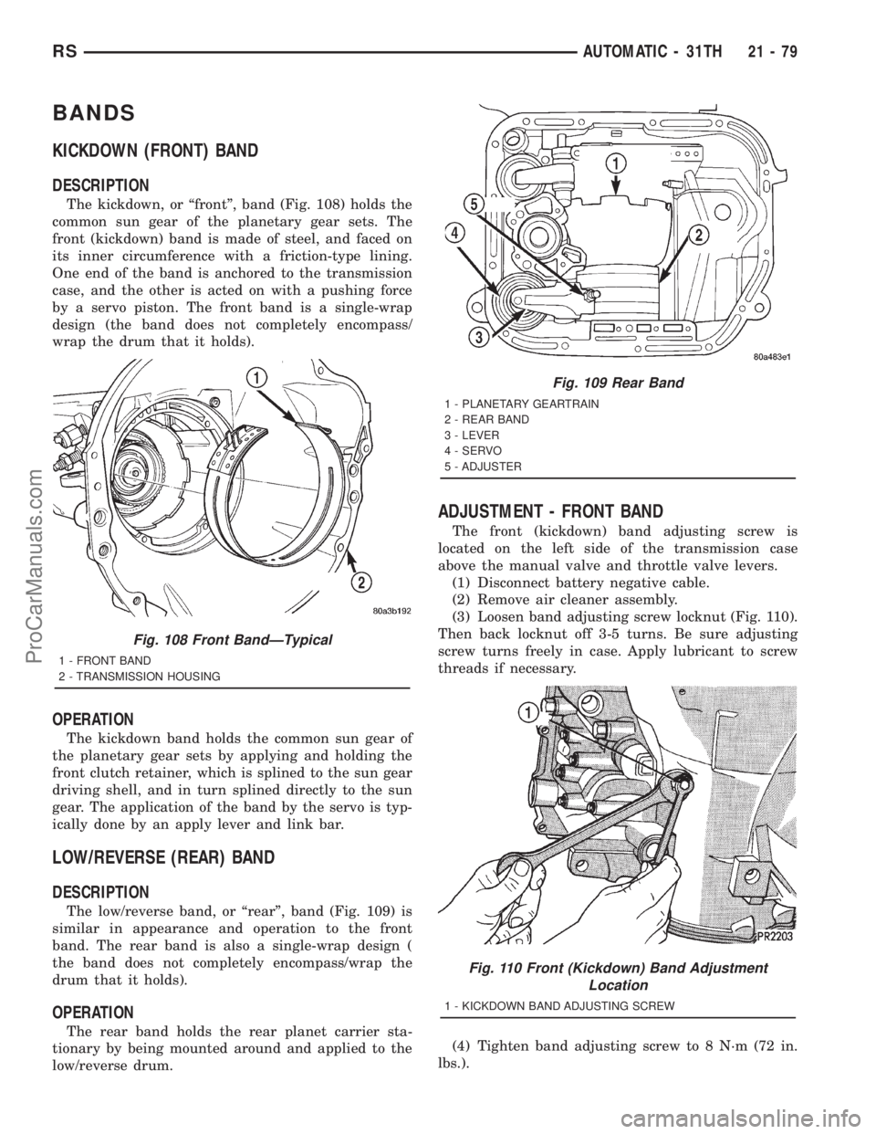
The kickdown, or ªfrontº, band (Fig. 108) holds the
common sun gear of the planetary gear sets. The
front (kickdown) band is made of steel, and faced on
its inner circumference with a friction-type lining.
One end of the band is anchored to the transmission
case, and the other is acted on with a pushing force
by a servo piston. The front band is a single-wrap
design (the band does not completely encompass/
wrap the drum that it holds).
OPERATION
The kickdown band holds the common sun gear of
the planetary gear sets by applying and holding the
front clutch retainer, which is splined to the sun gear
driving shell, and in turn splined directly to the sun
gear. The application of the band by the servo is typ-
ically done by an apply lever and link bar.
LOW/REVERSE (REAR) BAND
DESCRIPTION
The low/reverse band, or ªrearº, band (Fig. 109) is
similar in appearance and operation to the front
band. The rear band is also a single-wrap design (
the band does not completely encompass/wrap the
drum that it holds).
OPERATION
The rear band holds the rear planet carrier sta-
tionary by being mounted around and applied to the
low/reverse drum.
ADJUSTMENT - FRONT BAND
The front (kickdown) band adjusting screw is
located on the left side of the transmission case
above the manual valve and throttle valve levers.
(1) Disconnect battery negative cable.
(2) Remove air cleaner assembly.
(3) Loosen band adjusting screw locknut (Fig. 110).
Then back locknut off 3-5 turns. Be sure adjusting
screw turns freely in case. Apply lubricant to screw
threads if necessary.
(4) Tighten band adjusting screw to 8 N´m (72 in.
lbs.).
Fig. 108 Front BandÐTypical
1 - FRONT BAND
2 - TRANSMISSION HOUSING
Fig. 109 Rear Band
1 - PLANETARY GEARTRAIN
2 - REAR BAND
3 - LEVER
4 - SERVO
5 - ADJUSTER
Fig. 110 Front (Kickdown) Band Adjustment
Location
1 - KICKDOWN BAND ADJUSTING SCREW
RSAUTOMATIC - 31TH21-79
ProCarManuals.com
Page 1577 of 2321
(5) Back off front band adjusting screw 2ò turns.
(6) Hold adjuster screw in position and tighten
locknut to 47 N´m (35 ft. lbs.) torque.
(7) Install air cleaner assembly.
(8) Connect battery negative cable.
ADJUSTMENTS - REAR BAND
The transmission oil pan must be removed for
access to the rear (low/reverse) band adjusting screw.
(1) Raise vehicle.
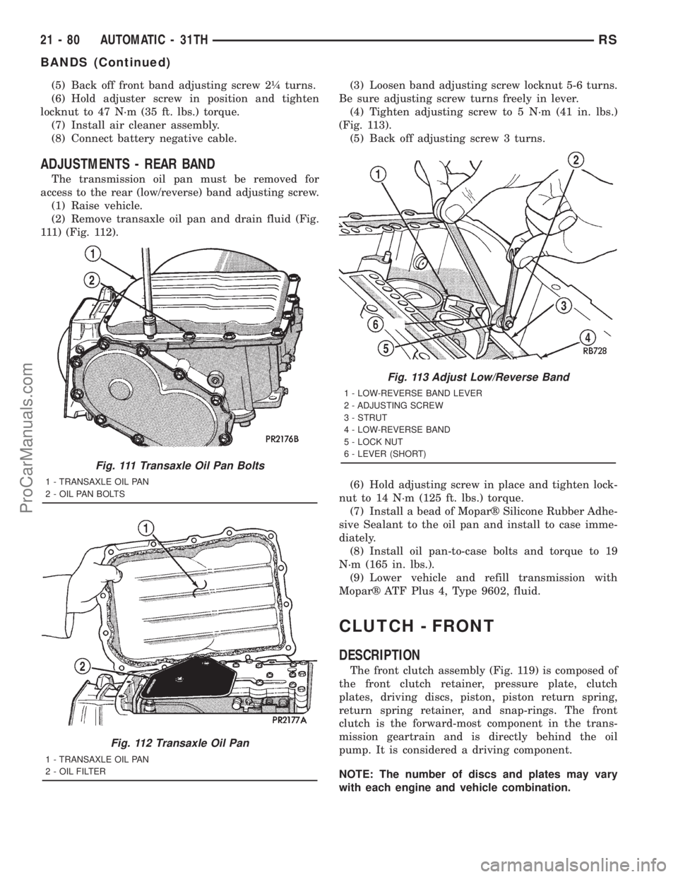
(2) Remove transaxle oil pan and drain fluid (Fig.
111) (Fig. 112).(3) Loosen band adjusting screw locknut 5-6 turns.
Be sure adjusting screw turns freely in lever.
(4) Tighten adjusting screw to 5 N´m (41 in. lbs.)
(Fig. 113).
(5) Back off adjusting screw 3 turns.
(6) Hold adjusting screw in place and tighten lock-
nut to 14 N´m (125 ft. lbs.) torque.
(7) Install a bead of Moparž Silicone Rubber Adhe-
sive Sealant to the oil pan and install to case imme-
diately.
(8) Install oil pan-to-case bolts and torque to 19
N´m (165 in. lbs.).
(9) Lower vehicle and refill transmission with
Moparž ATF Plus 4, Type 9602, fluid.
CLUTCH - FRONT
DESCRIPTION
The front clutch assembly (Fig. 119) is composed of
the front clutch retainer, pressure plate, clutch
plates, driving discs, piston, piston return spring,
return spring retainer, and snap-rings. The front
clutch is the forward-most component in the trans-
mission geartrain and is directly behind the oil
pump. It is considered a driving component.
NOTE: The number of discs and plates may vary
with each engine and vehicle combination.
Fig. 111 Transaxle Oil Pan Bolts
1 - TRANSAXLE OIL PAN
2 - OIL PAN BOLTS
Fig. 112 Transaxle Oil Pan
1 - TRANSAXLE OIL PAN
2 - OIL FILTER
Fig. 113 Adjust Low/Reverse Band
1 - LOW-REVERSE BAND LEVER
2 - ADJUSTING SCREW
3 - STRUT
4 - LOW-REVERSE BAND
5 - LOCK NUT
6 - LEVER (SHORT)
21 - 80 AUTOMATIC - 31THRS
BANDS (Continued)
ProCarManuals.com
Page 1597 of 2321
applied, move selector lever momentarily to each
position, ending in the park or neutral position.
(8) Check the transaxle fluid level and add an
appropriate amount to bring the transaxle fluid level
to 3mm (1/8 in.) below the ªADDº mark on the dip-
stick (Fig. 168).
(9) Recheck the fluid level after the transaxle has
reached normal operating temperature (180ÉF.).
(Refer to 21 - TRANSMISSION/TRANSAXLE/AUTO-
MATIC - 31TH/FLUID - STANDARD PROCEDURE)
(10) To prevent dirt from entering transaxle, make
certain that dipstick is fully seated into the dipstick
opening.
GEAR SHIFT CABLE
REMOVAL
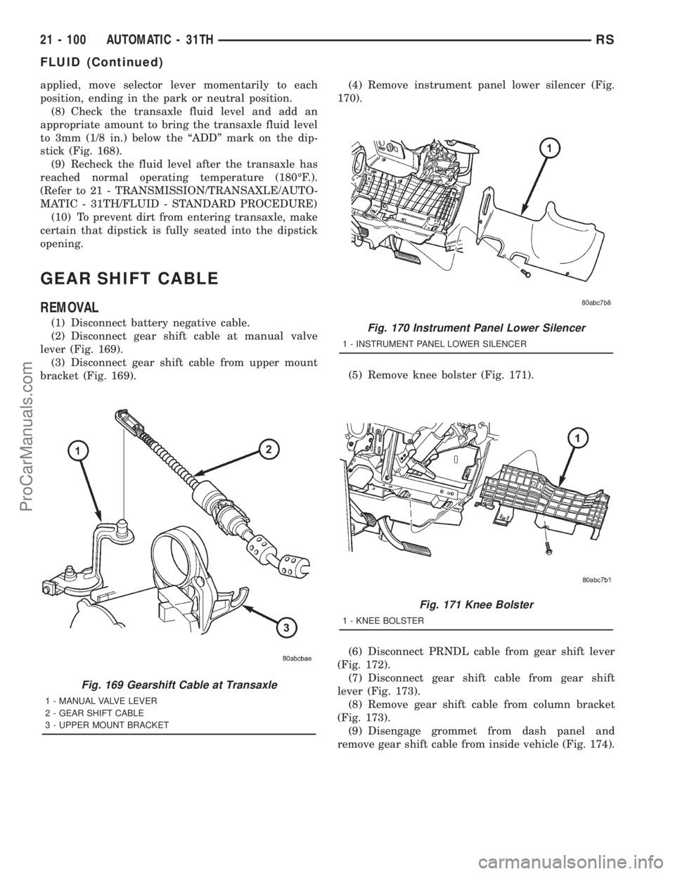
(1) Disconnect battery negative cable.
(2) Disconnect gear shift cable at manual valve
lever (Fig. 169).
(3) Disconnect gear shift cable from upper mount
bracket (Fig. 169).(4) Remove instrument panel lower silencer (Fig.
170).
(5) Remove knee bolster (Fig. 171).
(6) Disconnect PRNDL cable from gear shift lever
(Fig. 172).
(7) Disconnect gear shift cable from gear shift
lever (Fig. 173).
(8) Remove gear shift cable from column bracket
(Fig. 173).
(9) Disengage grommet from dash panel and
remove gear shift cable from inside vehicle (Fig. 174).
Fig. 169 Gearshift Cable at Transaxle
1 - MANUAL VALVE LEVER
2 - GEAR SHIFT CABLE
3 - UPPER MOUNT BRACKET
Fig. 170 Instrument Panel Lower Silencer
1 - INSTRUMENT PANEL LOWER SILENCER
Fig. 171 Knee Bolster
1 - KNEE BOLSTER
21 - 100 AUTOMATIC - 31THRS
FLUID (Continued)
ProCarManuals.com