2001 DODGE TOWN AND COUNTRY battery
[x] Cancel search: batteryPage 1611 of 2321
OPERATION
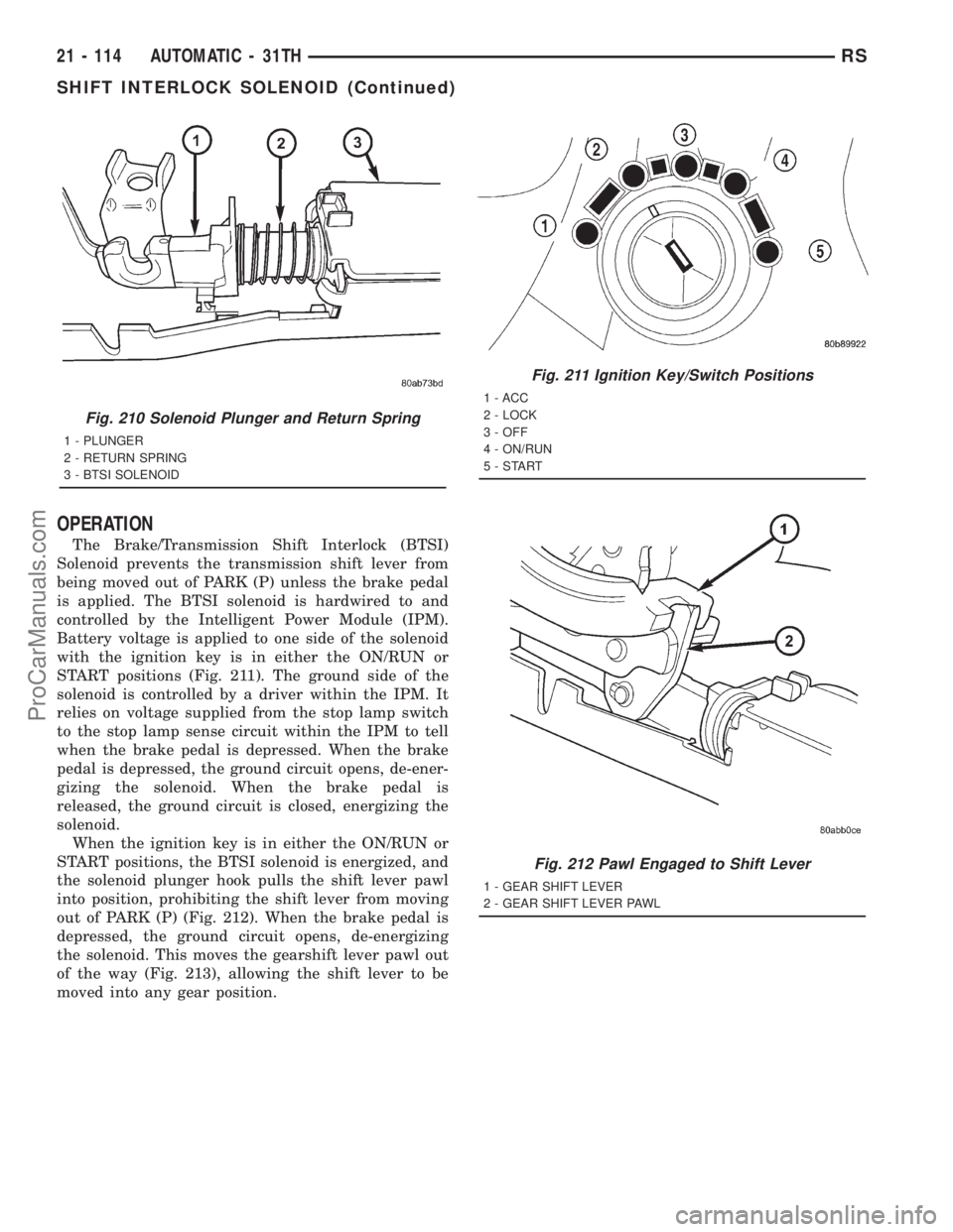
The Brake/Transmission Shift Interlock (BTSI)
Solenoid prevents the transmission shift lever from
being moved out of PARK (P) unless the brake pedal
is applied. The BTSI solenoid is hardwired to and
controlled by the Intelligent Power Module (IPM).
Battery voltage is applied to one side of the solenoid
with the ignition key is in either the ON/RUN or
START positions (Fig. 211). The ground side of the
solenoid is controlled by a driver within the IPM. It
relies on voltage supplied from the stop lamp switch
to the stop lamp sense circuit within the IPM to tell
when the brake pedal is depressed. When the brake
pedal is depressed, the ground circuit opens, de-ener-
gizing the solenoid. When the brake pedal is
released, the ground circuit is closed, energizing the
solenoid.
When the ignition key is in either the ON/RUN or
START positions, the BTSI solenoid is energized, and
the solenoid plunger hook pulls the shift lever pawl
into position, prohibiting the shift lever from moving
out of PARK (P) (Fig. 212). When the brake pedal is
depressed, the ground circuit opens, de-energizing
the solenoid. This moves the gearshift lever pawl out
of the way (Fig. 213), allowing the shift lever to be
moved into any gear position.
Fig. 210 Solenoid Plunger and Return Spring
1 - PLUNGER
2 - RETURN SPRING
3 - BTSI SOLENOID
Fig. 211 Ignition Key/Switch Positions
1 - ACC
2 - LOCK
3 - OFF
4 - ON/RUN
5-START
Fig. 212 Pawl Engaged to Shift Lever
1 - GEAR SHIFT LEVER
2 - GEAR SHIFT LEVER PAWL
21 - 114 AUTOMATIC - 31THRS
SHIFT INTERLOCK SOLENOID (Continued)
ProCarManuals.com
Page 1612 of 2321
A conventional mechanical interlock system is also
used. This system manually prohibits shifter move-
ment when the ignition switch is in the LOCK or
ACC positions. Solenoid operation is not required in
these key positions. When the ignition key is in the
OFF position, the gearshift lever is unrestricted, and
able to move into any gear position (during towing,
dead battery, etc.).
For intended BTSI system operation, refer to the
following chart:
ACTION EXPECTED RESPONSE
1. Turn key to the9OFF9
position.1. Shifter CAN be shifted
out of park.
2. Turn key to the
9ON/RUN9position.2. Shifter CANNOT be
shifted out of park.
3. Turn key to the
9ON/RUN9position and
depress the brake pedal.3. Shifter CAN be shifted
out of park.
4. Leave shifter in any
gear and try to return key
to the9LOCK9or9ACC9
position.4. Key cannot be
returned to the9LOCK9or
9ACC9position.
5. Return shifter to
9PARK9and try to remove
the key.5. Key can be removed
(after returning to9LOCK9
position).
6. With the key removed,
try to shift out of9PARK9.6. Shifter cannot be
shifted out of9PARK9.
NOTE: Any failure to meet these expected
responses requires system adjustment or repair.
DIAGNOSIS AND TESTING - BRAKE/
TRANSMISSION SHIFT INTERLOCK SOLENOID
For intended BTSI system operation, refer to the
following chart:
ACTION EXPECTED RESPONSE
1. Turn key to the9OFF9
position.1. Shifter CAN be shifted
out of park.
2. Turn key to the
9ON/RUN9position.2. Shifter CANNOT be
shifted out of park.
3. Turn key to the
9ON/RUN9position and
depress the brake pedal.3. Shifter CAN be shifted
out of park.
4. Leave shifter in any
gear and try to return key
to the9LOCK9or9ACC9
position.4. Key cannot be
returned to the9LOCK9or
9ACC9position.
5. Return shifter to
9PARK9and try to remove
the key.5. Key can be removed
(after returning to9LOCK9
position).
6. With the key removed,
try to shift out of9PARK9.6. Shifter cannot be
shifted out of9PARK9.
NOTE: Any failure to meet these expected
responses requires system repair. Refer to the
appropriate Diagnostic Information.
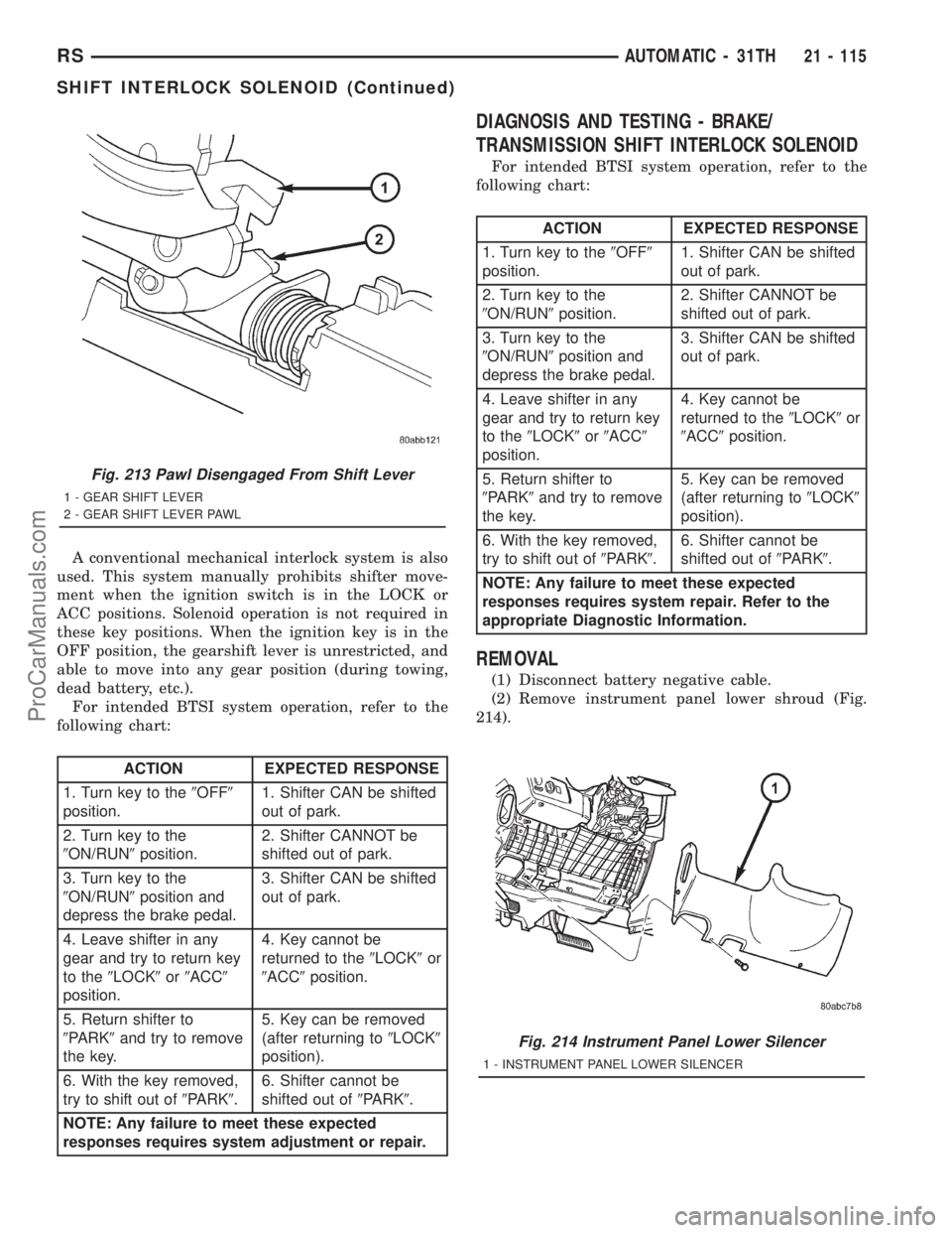
REMOVAL
(1) Disconnect battery negative cable.
(2) Remove instrument panel lower shroud (Fig.
214).
Fig. 213 Pawl Disengaged From Shift Lever
1 - GEAR SHIFT LEVER
2 - GEAR SHIFT LEVER PAWL
Fig. 214 Instrument Panel Lower Silencer
1 - INSTRUMENT PANEL LOWER SILENCER
RSAUTOMATIC - 31TH21 - 115
SHIFT INTERLOCK SOLENOID (Continued)
ProCarManuals.com
Page 1614 of 2321
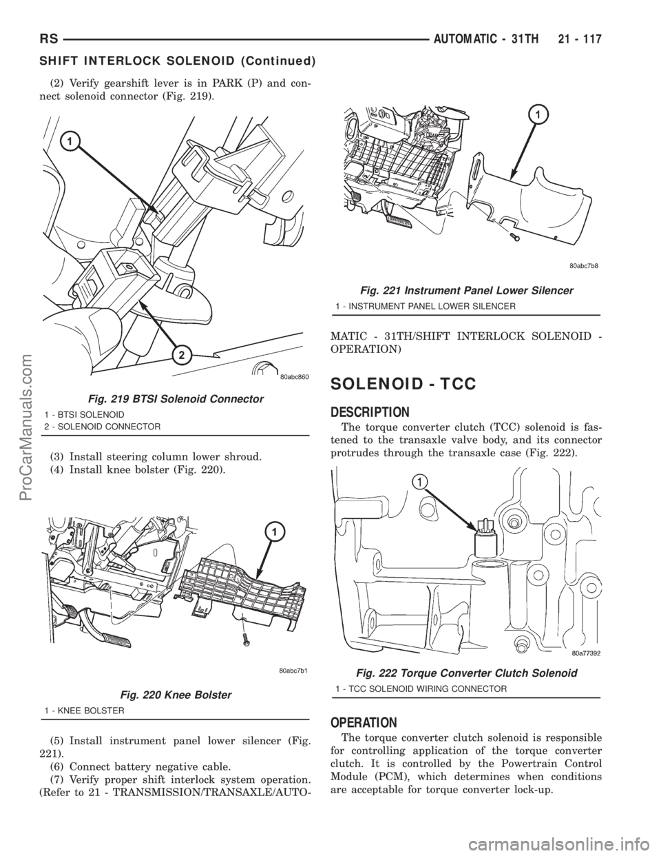
(2) Verify gearshift lever is in PARK (P) and con-
nect solenoid connector (Fig. 219).
(3) Install steering column lower shroud.
(4) Install knee bolster (Fig. 220).
(5) Install instrument panel lower silencer (Fig.
221).
(6) Connect battery negative cable.
(7) Verify proper shift interlock system operation.
(Refer to 21 - TRANSMISSION/TRANSAXLE/AUTO-MATIC - 31TH/SHIFT INTERLOCK SOLENOID -
OPERATION)
SOLENOID - TCC
DESCRIPTION
The torque converter clutch (TCC) solenoid is fas-
tened to the transaxle valve body, and its connector
protrudes through the transaxle case (Fig. 222).
OPERATION
The torque converter clutch solenoid is responsible
for controlling application of the torque converter
clutch. It is controlled by the Powertrain Control
Module (PCM), which determines when conditions
are acceptable for torque converter lock-up.
Fig. 219 BTSI Solenoid Connector
1 - BTSI SOLENOID
2 - SOLENOID CONNECTOR
Fig. 220 Knee Bolster
1 - KNEE BOLSTER
Fig. 221 Instrument Panel Lower Silencer
1 - INSTRUMENT PANEL LOWER SILENCER
Fig. 222 Torque Converter Clutch Solenoid
1 - TCC SOLENOID WIRING CONNECTOR
RSAUTOMATIC - 31TH21 - 117
SHIFT INTERLOCK SOLENOID (Continued)
ProCarManuals.com
Page 1615 of 2321
REMOVAL
(1) Remove valve body from transaxle. (Refer to 21
- TRANSMISSION/TRANSAXLE/AUTOMATIC -
31TH/VALVE BODY - REMOVAL)
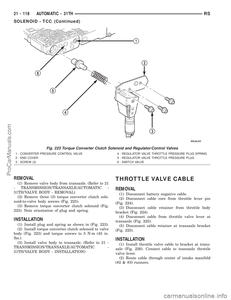
(2) Remove three (3) torque converter clutch sole-
noid-to-valve body screws (Fig. 223).
(3) Remove torque converter clutch solenoid (Fig.
223). Note orientation of plug and spring.
INSTALLATION
(1) Install plug and spring as shown in (Fig. 223).
(2) Install torque converter clutch solenoid to valve
body (Fig. 223) and torque screws to 5 N´m (45 in.
lbs.).
(3) Install valve body to transaxle. (Refer to 21 -
TRANSMISSION/TRANSAXLE/AUTOMATIC -
31TH/VALVE BODY - INSTALLATION)
THROTTLE VALVE CABLE
REMOVAL
(1) Disconnect battery negative cable.
(2) Disconnect cable core from throttle lever pin
(Fig. 224).
(3) Disconnect cable retainer from throttle body
bracket (Fig. 224).
(4) Disconnect cable from throttle valve lever at
transaxle (Fig. 225).
(5) Disconnect cable retainer at transaxle bracket
(Fig. 225).
INSTALLATION
(1) Install throttle valve cable to bracket at trans-
axle (Fig. 226). Connect cable to transaxle throttle
valve lever.
(2) Route cable through center of intake manifold
(#2 & #3) runners.
Fig. 223 Torque Converter Clutch Solenoid and Regulator/Control Valves
1 - CONVERTER PRESSURE CONTROL VALVE
2 - END COVER
3 - SCREW (3)4 - REGULATOR VALVE THROTTLE PRESSURE PLUG SPRING
5 - REGULATOR VALVE THROTTLE PRESSURE PLUG
6 - SWITCH VALVE
21 - 118 AUTOMATIC - 31THRS
SOLENOID - TCC (Continued)
ProCarManuals.com
Page 1616 of 2321
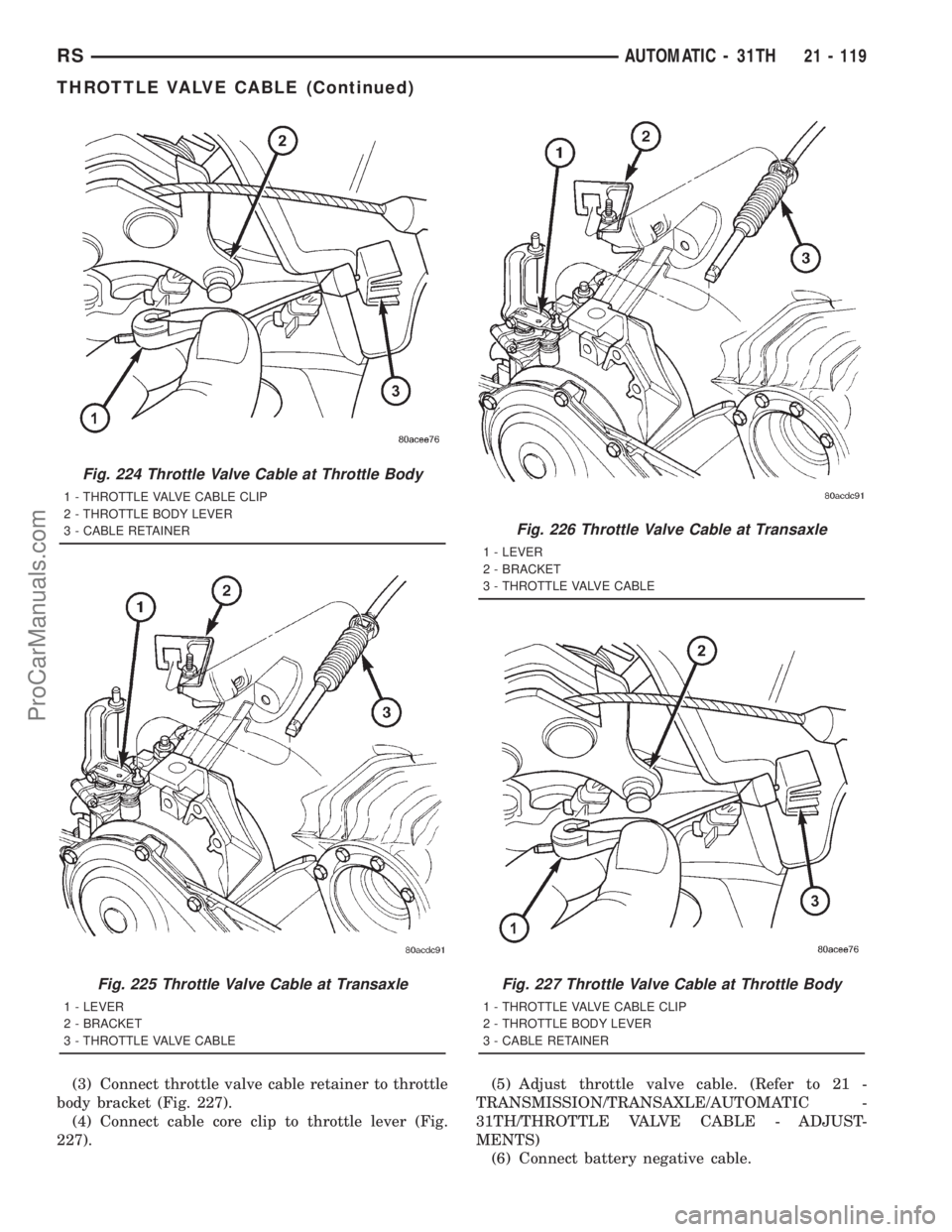
(3) Connect throttle valve cable retainer to throttle
body bracket (Fig. 227).
(4) Connect cable core clip to throttle lever (Fig.
227).(5) Adjust throttle valve cable. (Refer to 21 -
TRANSMISSION/TRANSAXLE/AUTOMATIC -
31TH/THROTTLE VALVE CABLE - ADJUST-
MENTS)
(6) Connect battery negative cable.
Fig. 224 Throttle Valve Cable at Throttle Body
1 - THROTTLE VALVE CABLE CLIP
2 - THROTTLE BODY LEVER
3 - CABLE RETAINER
Fig. 225 Throttle Valve Cable at Transaxle
1 - LEVER
2 - BRACKET
3 - THROTTLE VALVE CABLE
Fig. 226 Throttle Valve Cable at Transaxle
1 - LEVER
2 - BRACKET
3 - THROTTLE VALVE CABLE
Fig. 227 Throttle Valve Cable at Throttle Body
1 - THROTTLE VALVE CABLE CLIP
2 - THROTTLE BODY LEVER
3 - CABLE RETAINER
RSAUTOMATIC - 31TH21 - 119
THROTTLE VALVE CABLE (Continued)
ProCarManuals.com
Page 1639 of 2321
ADJUSTMENT - TRANSFER SHAFT BEARING
(1) Use Tool L-4434 to remove the retaining nut
and washer. Remove the transfer shaft gear using
Tool L-4407.
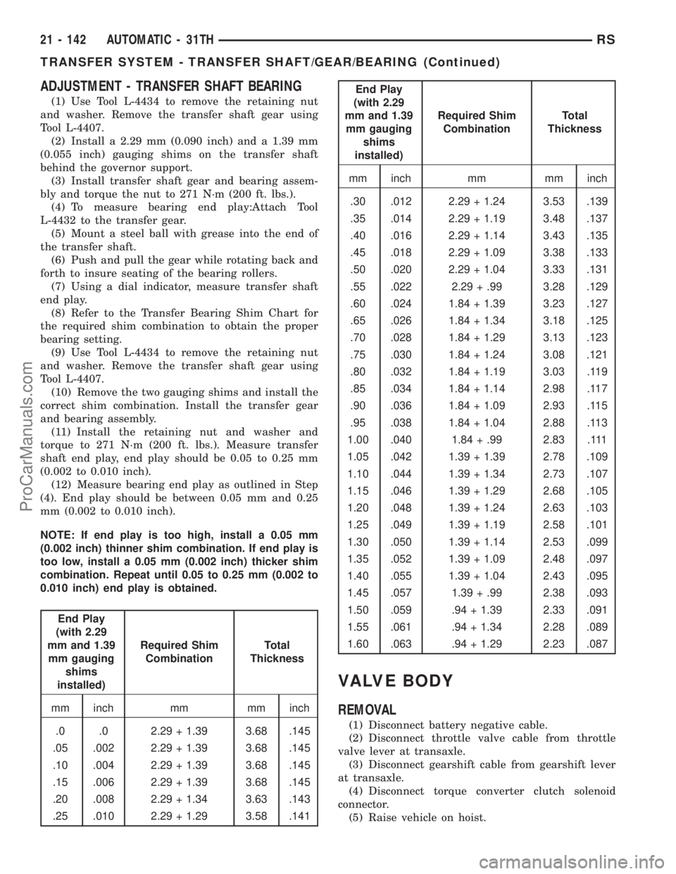
(2) Install a 2.29 mm (0.090 inch) and a 1.39 mm
(0.055 inch) gauging shims on the transfer shaft
behind the governor support.
(3) Install transfer shaft gear and bearing assem-
bly and torque the nut to 271 N´m (200 ft. lbs.).
(4) To measure bearing end play:Attach Tool
L-4432 to the transfer gear.
(5) Mount a steel ball with grease into the end of
the transfer shaft.
(6) Push and pull the gear while rotating back and
forth to insure seating of the bearing rollers.
(7) Using a dial indicator, measure transfer shaft
end play.
(8) Refer to the Transfer Bearing Shim Chart for
the required shim combination to obtain the proper
bearing setting.
(9) Use Tool L-4434 to remove the retaining nut
and washer. Remove the transfer shaft gear using
Tool L-4407.
(10) Remove the two gauging shims and install the
correct shim combination. Install the transfer gear
and bearing assembly.
(11) Install the retaining nut and washer and
torque to 271 N´m (200 ft. lbs.). Measure transfer
shaft end play, end play should be 0.05 to 0.25 mm
(0.002 to 0.010 inch).
(12) Measure bearing end play as outlined in Step
(4). End play should be between 0.05 mm and 0.25
mm (0.002 to 0.010 inch).
NOTE: If end play is too high, install a 0.05 mm
(0.002 inch) thinner shim combination. If end play is
too low, install a 0.05 mm (0.002 inch) thicker shim
combination. Repeat until 0.05 to 0.25 mm (0.002 to
0.010 inch) end play is obtained.
End Play
(with 2.29
mm and 1.39
mm gauging
shims
installed)Required Shim
CombinationTotal
Thickness
mm inch mm mm inch
.0 .0 2.29 + 1.39 3.68 .145
.05 .002 2.29 + 1.39 3.68 .145
.10 .004 2.29 + 1.39 3.68 .145
.15 .006 2.29 + 1.39 3.68 .145
.20 .008 2.29 + 1.34 3.63 .143
.25 .010 2.29 + 1.29 3.58 .141
End Play
(with 2.29
mm and 1.39
mm gauging
shims
installed)Required Shim
CombinationTotal
Thickness
mm inch mm mm inch
.30 .012 2.29 + 1.24 3.53 .139
.35 .014 2.29 + 1.19 3.48 .137
.40 .016 2.29 + 1.14 3.43 .135
.45 .018 2.29 + 1.09 3.38 .133
.50 .020 2.29 + 1.04 3.33 .131
.55 .022 2.29 + .99 3.28 .129
.60 .024 1.84 + 1.39 3.23 .127
.65 .026 1.84 + 1.34 3.18 .125
.70 .028 1.84 + 1.29 3.13 .123
.75 .030 1.84 + 1.24 3.08 .121
.80 .032 1.84 + 1.19 3.03 .119
.85 .034 1.84 + 1.14 2.98 .117
.90 .036 1.84 + 1.09 2.93 .115
.95 .038 1.84 + 1.04 2.88 .113
1.00 .040 1.84 + .99 2.83 .111
1.05 .042 1.39 + 1.39 2.78 .109
1.10 .044 1.39 + 1.34 2.73 .107
1.15 .046 1.39 + 1.29 2.68 .105
1.20 .048 1.39 + 1.24 2.63 .103
1.25 .049 1.39 + 1.19 2.58 .101
1.30 .050 1.39 + 1.14 2.53 .099
1.35 .052 1.39 + 1.09 2.48 .097
1.40 .055 1.39 + 1.04 2.43 .095
1.45 .057 1.39 + .99 2.38 .093
1.50 .059 .94 + 1.39 2.33 .091
1.55 .061 .94 + 1.34 2.28 .089
1.60 .063 .94 + 1.29 2.23 .087
VALVE BODY
REMOVAL
(1) Disconnect battery negative cable.
(2) Disconnect throttle valve cable from throttle
valve lever at transaxle.
(3) Disconnect gearshift cable from gearshift lever
at transaxle.
(4) Disconnect torque converter clutch solenoid
connector.
(5) Raise vehicle on hoist.
21 - 142 AUTOMATIC - 31THRS
TRANSFER SYSTEM - TRANSFER SHAFT/GEAR/BEARING (Continued)
ProCarManuals.com
Page 1653 of 2321
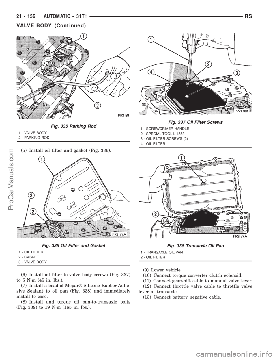
(5) Install oil filter and gasket (Fig. 336).
(6) Install oil filter-to-valve body screws (Fig. 337)
to 5 N´m (45 in. lbs.).
(7) Install a bead of Moparž Silicone Rubber Adhe-
sive Sealant to oil pan (Fig. 338) and immediately
install to case.
(8) Install and torque oil pan-to-transaxle bolts
(Fig. 339) to 19 N´m (165 in. lbs.).(9) Lower vehicle.
(10) Connect torque converter clutch solenoid.
(11) Connect gearshift cable to manual valve lever.
(12) Connect throttle valve cable to throttle valve
lever at transaxle.
(13) Connect battery negative cable.
Fig. 335 Parking Rod
1 - VALVE BODY
2 - PARKING ROD
Fig. 336 Oil Filter and Gasket
1 - OIL FILTER
2 - GASKET
3 - VALVE BODY
Fig. 337 Oil Filter Screws
1 - SCREWDRIVER HANDLE
2 - SPECIAL TOOL L-4553
3 - OIL FILTER SCREWS (2)
4 - OIL FILTER
Fig. 338 Transaxle Oil Pan
1 - TRANSAXLE OIL PAN
2 - OIL FILTER
21 - 156 AUTOMATIC - 31THRS
VALVE BODY (Continued)
ProCarManuals.com
Page 1662 of 2321
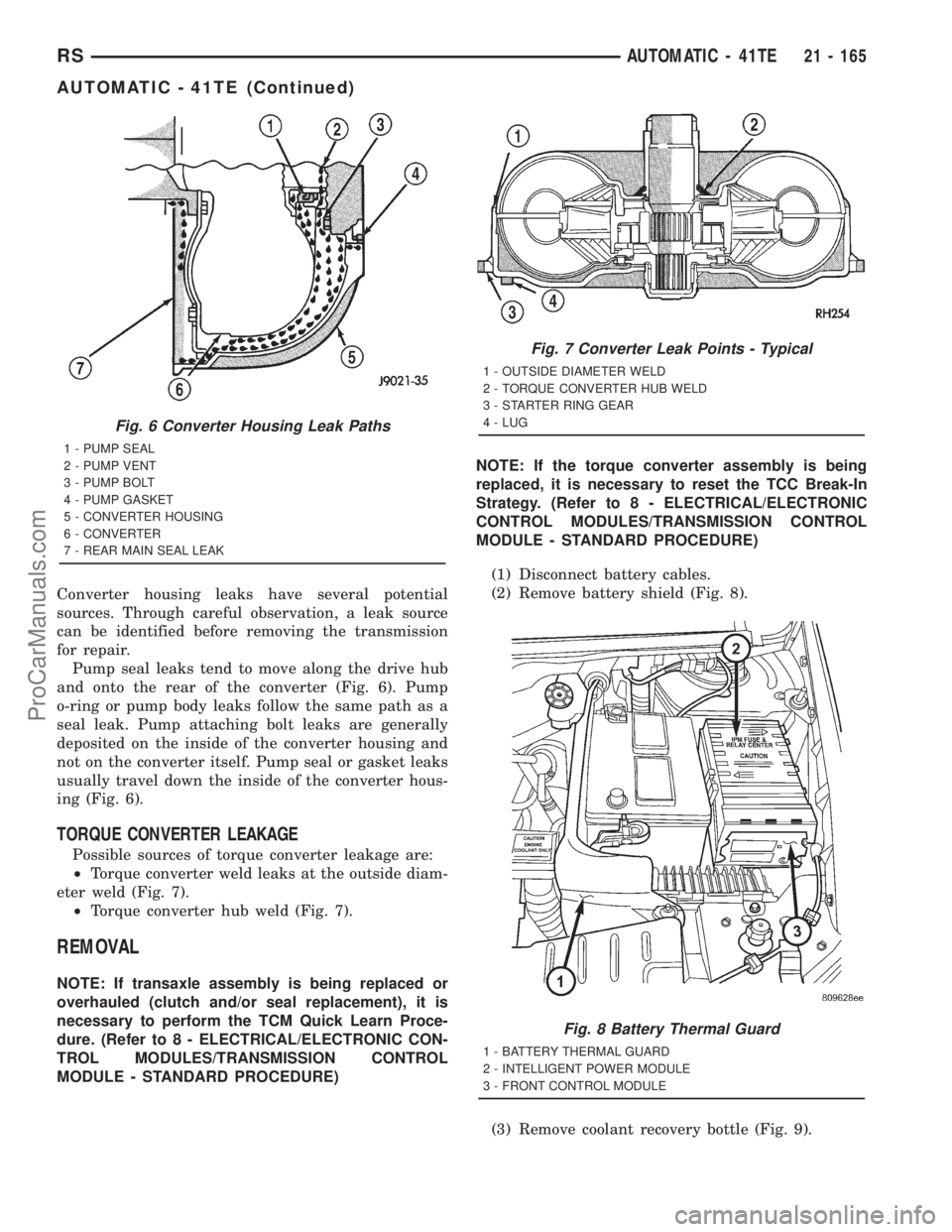
Converter housing leaks have several potential
sources. Through careful observation, a leak source
can be identified before removing the transmission
for repair.
Pump seal leaks tend to move along the drive hub
and onto the rear of the converter (Fig. 6). Pump
o-ring or pump body leaks follow the same path as a
seal leak. Pump attaching bolt leaks are generally
deposited on the inside of the converter housing and
not on the converter itself. Pump seal or gasket leaks
usually travel down the inside of the converter hous-
ing (Fig. 6).
TORQUE CONVERTER LEAKAGE
Possible sources of torque converter leakage are:
²Torque converter weld leaks at the outside diam-
eter weld (Fig. 7).
²Torque converter hub weld (Fig. 7).
REMOVAL
NOTE: If transaxle assembly is being replaced or
overhauled (clutch and/or seal replacement), it is
necessary to perform the TCM Quick Learn Proce-
dure. (Refer to 8 - ELECTRICAL/ELECTRONIC CON-
TROL MODULES/TRANSMISSION CONTROL
MODULE - STANDARD PROCEDURE)NOTE: If the torque converter assembly is being
replaced, it is necessary to reset the TCC Break-In
Strategy. (Refer to 8 - ELECTRICAL/ELECTRONIC
CONTROL MODULES/TRANSMISSION CONTROL
MODULE - STANDARD PROCEDURE)
(1) Disconnect battery cables.
(2) Remove battery shield (Fig. 8).
(3) Remove coolant recovery bottle (Fig. 9).
Fig. 6 Converter Housing Leak Paths
1 - PUMP SEAL
2 - PUMP VENT
3 - PUMP BOLT
4 - PUMP GASKET
5 - CONVERTER HOUSING
6 - CONVERTER
7 - REAR MAIN SEAL LEAK
Fig. 7 Converter Leak Points - Typical
1 - OUTSIDE DIAMETER WELD
2 - TORQUE CONVERTER HUB WELD
3 - STARTER RING GEAR
4 - LUG
Fig. 8 Battery Thermal Guard
1 - BATTERY THERMAL GUARD
2 - INTELLIGENT POWER MODULE
3 - FRONT CONTROL MODULE
RSAUTOMATIC - 41TE21 - 165
AUTOMATIC - 41TE (Continued)
ProCarManuals.com