Page 1799 of 2321

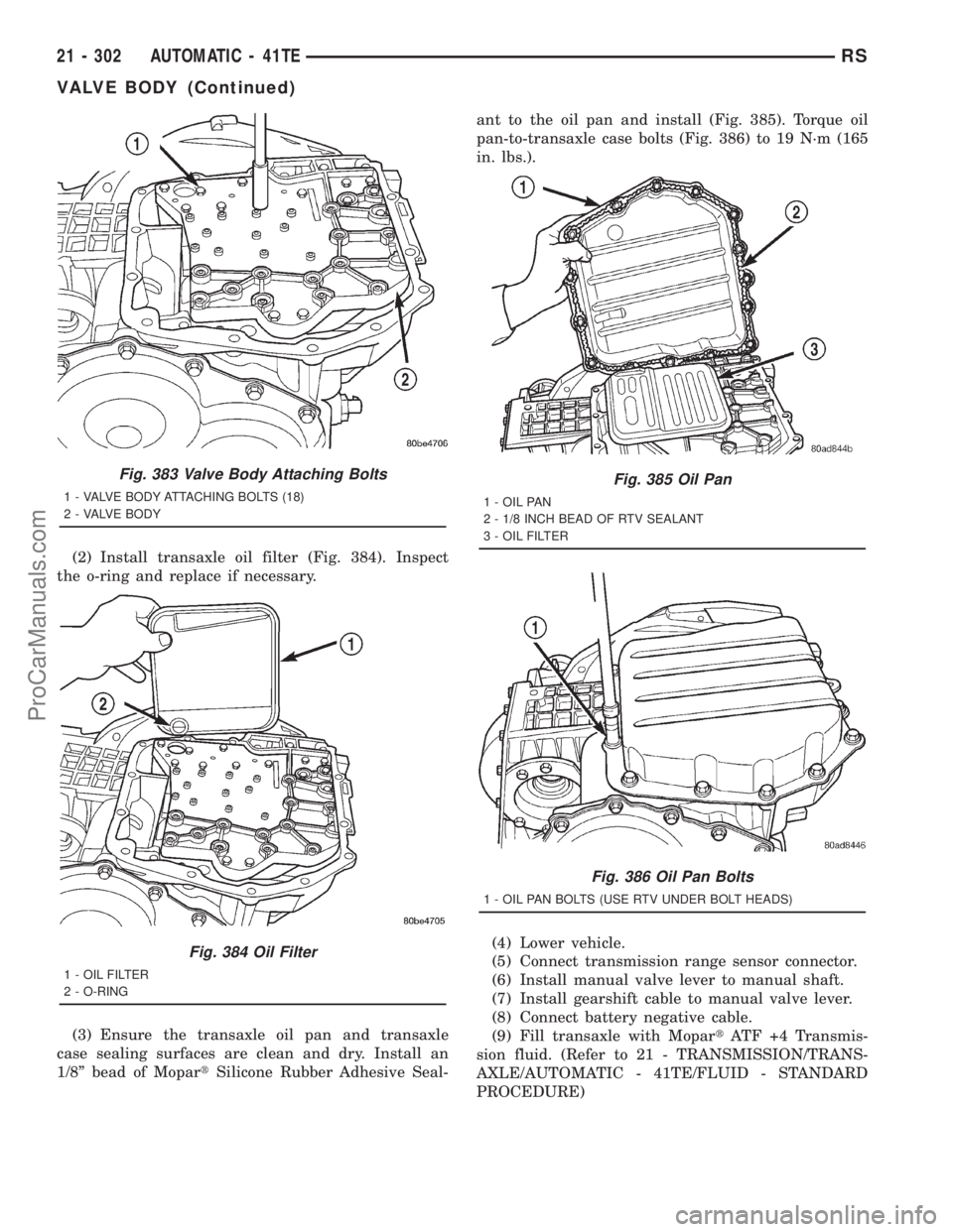
(2) Install transaxle oil filter (Fig. 384). Inspect
the o-ring and replace if necessary.
(3) Ensure the transaxle oil pan and transaxle
case sealing surfaces are clean and dry. Install an
1/8º bead of MopartSilicone Rubber Adhesive Seal-ant to the oil pan and install (Fig. 385). Torque oil
pan-to-transaxle case bolts (Fig. 386) to 19 N´m (165
in. lbs.).
(4) Lower vehicle.
(5) Connect transmission range sensor connector.
(6) Install manual valve lever to manual shaft.
(7) Install gearshift cable to manual valve lever.
(8) Connect battery negative cable.
(9) Fill transaxle with MopartATF +4 Transmis-
sion fluid. (Refer to 21 - TRANSMISSION/TRANS-
AXLE/AUTOMATIC - 41TE/FLUID - STANDARD
PROCEDURE)
Fig. 383 Valve Body Attaching Bolts
1 - VALVE BODY ATTACHING BOLTS (18)
2 - VALVE BODY
Fig. 384 Oil Filter
1 - OIL FILTER
2 - O-RING
Fig. 385 Oil Pan
1 - OIL PAN
2 - 1/8 INCH BEAD OF RTV SEALANT
3 - OIL FILTER
Fig. 386 Oil Pan Bolts
1 - OIL PAN BOLTS (USE RTV UNDER BOLT HEADS)
21 - 302 AUTOMATIC - 41TERS
VALVE BODY (Continued)
ProCarManuals.com
Page 1812 of 2321
REMOVAL - 2.5L TD
(1) Raise hood.
(2) Disconnect both battery cables.
(3) Remove battery thermal shield and clutch cable
eyelet (LHD only) (Fig. 16).
(4) Remove battery hold down bolt, clamp, and
battery (Fig. 17).
Fig. 14 Starter Motor Removal/Installation
1 - STARTER MOTOR
2 - BOLT (3)
Fig. 15 Transaxle Upper Mount
1 - MOUNT
2 - BOLT (4)
Fig. 16 Battery Thermal Shield
1 - BATTERY THERMAL SHIELD
Fig. 17 Battery and Hold-Down Clamp
1 - BATTERY
2 - HOLD-DOWN CLAMP
RGT850 MANUAL TRANSAXLE21a-13
T850 MANUAL TRANSAXLE (Continued)
ProCarManuals.com
Page 1813 of 2321
(5) Remove battery tray (Fig. 18). Disconnect bat-
tery temperature sensor.
(6) Remove coolant recovery bottle from bracket.
(7) Remove coolant recovery bottle mounting
bracket (Fig. 19).
(8) Disconnect gearshift cables from shift levers/
cover assembly (Fig. 20).
(9) Remove gearshift cable retaining clips from
mounting bracket (Fig. 20). Remove cables and
secure out of way.(10) Remove three (3) right engine mount bracket-
to-transaxle bolts (Fig. 21).
Fig. 18 Battery Tray
1 - BATTERY TRAY
Fig. 19 Coolant Recovery Bottle Bracket
1 - COOLANT RECOVERY BOTTLE BRACKET
2 - NUT
3 - MOUNT BRACKET
Fig. 20 Gearshift Cables at Transaxle
1 - SELECTOR CABLE
2 - CABLE RETAINER
3 - CABLE RETAINER
4 - CROSSOVER CABLE
5 - MOUNT BRACKET
Fig. 21 Transaxle Right Mount and Bracket
1 - MOUNT BRACKET
2 - BOLT (3)
3 - MOUNT
4 - BOLT (1)
21a - 14 T850 MANUAL TRANSAXLERG
T850 MANUAL TRANSAXLE (Continued)
ProCarManuals.com
Page 1832 of 2321

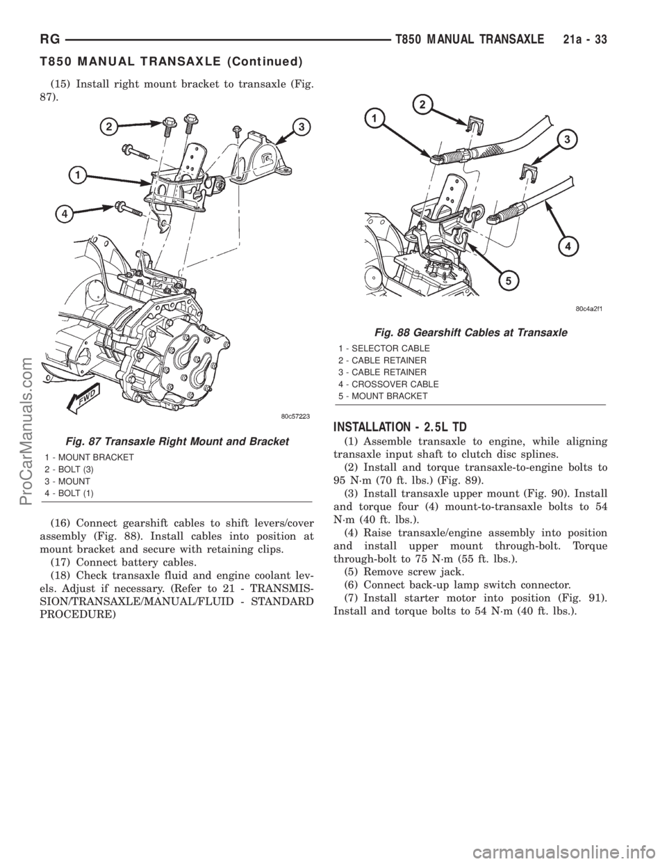
(15) Install right mount bracket to transaxle (Fig.
87).
(16) Connect gearshift cables to shift levers/cover
assembly (Fig. 88). Install cables into position at
mount bracket and secure with retaining clips.
(17) Connect battery cables.
(18) Check transaxle fluid and engine coolant lev-
els. Adjust if necessary. (Refer to 21 - TRANSMIS-
SION/TRANSAXLE/MANUAL/FLUID - STANDARD
PROCEDURE)
INSTALLATION - 2.5L TD
(1) Assemble transaxle to engine, while aligning
transaxle input shaft to clutch disc splines.
(2) Install and torque transaxle-to-engine bolts to
95 N´m (70 ft. lbs.) (Fig. 89).
(3) Install transaxle upper mount (Fig. 90). Install
and torque four (4) mount-to-transaxle bolts to 54
N´m (40 ft. lbs.).
(4) Raise transaxle/engine assembly into position
and install upper mount through-bolt. Torque
through-bolt to 75 N´m (55 ft. lbs.).
(5) Remove screw jack.
(6) Connect back-up lamp switch connector.
(7) Install starter motor into position (Fig. 91).
Install and torque bolts to 54 N´m (40 ft. lbs.).Fig. 87 Transaxle Right Mount and Bracket
1 - MOUNT BRACKET
2 - BOLT (3)
3 - MOUNT
4 - BOLT (1)
Fig. 88 Gearshift Cables at Transaxle
1 - SELECTOR CABLE
2 - CABLE RETAINER
3 - CABLE RETAINER
4 - CROSSOVER CABLE
5 - MOUNT BRACKET
RGT850 MANUAL TRANSAXLE21a-33
T850 MANUAL TRANSAXLE (Continued)
ProCarManuals.com
Page 1835 of 2321
(16) Connect gearshift cables to shift levers/cover
assembly (Fig. 95). Install cables into position at
mount bracket and secure with retaining clips.
(17) Install coolant recovery bottle bracket (Fig.
96).(18) Install coolant recovery bottle to bracket.
(19) Connect battery temperature sensor and
install battery tray (Fig. 97).
(20) Install battery, hold-down clamp and nut (Fig.
98).
Fig. 95 Gearshift Cables at Transaxle
1 - SELECTOR CABLE
2 - CABLE RETAINER
3 - CABLE RETAINER
4 - CROSSOVER CABLE
5 - MOUNT BRACKET
Fig. 96 Coolant Recovery Bottle Bracket
1 - COOLANT RECOVERY BOTTLE BRACKET
2 - NUT
3 - MOUNT BRACKET
Fig. 97 Battery Tray
1 - BATTERY TRAY
Fig. 98 Battery and Hold-Down Clamp
1 - BATTERY
2 - HOLD-DOWN CLAMP
21a - 36 T850 MANUAL TRANSAXLERG
T850 MANUAL TRANSAXLE (Continued)
ProCarManuals.com
Page 1836 of 2321

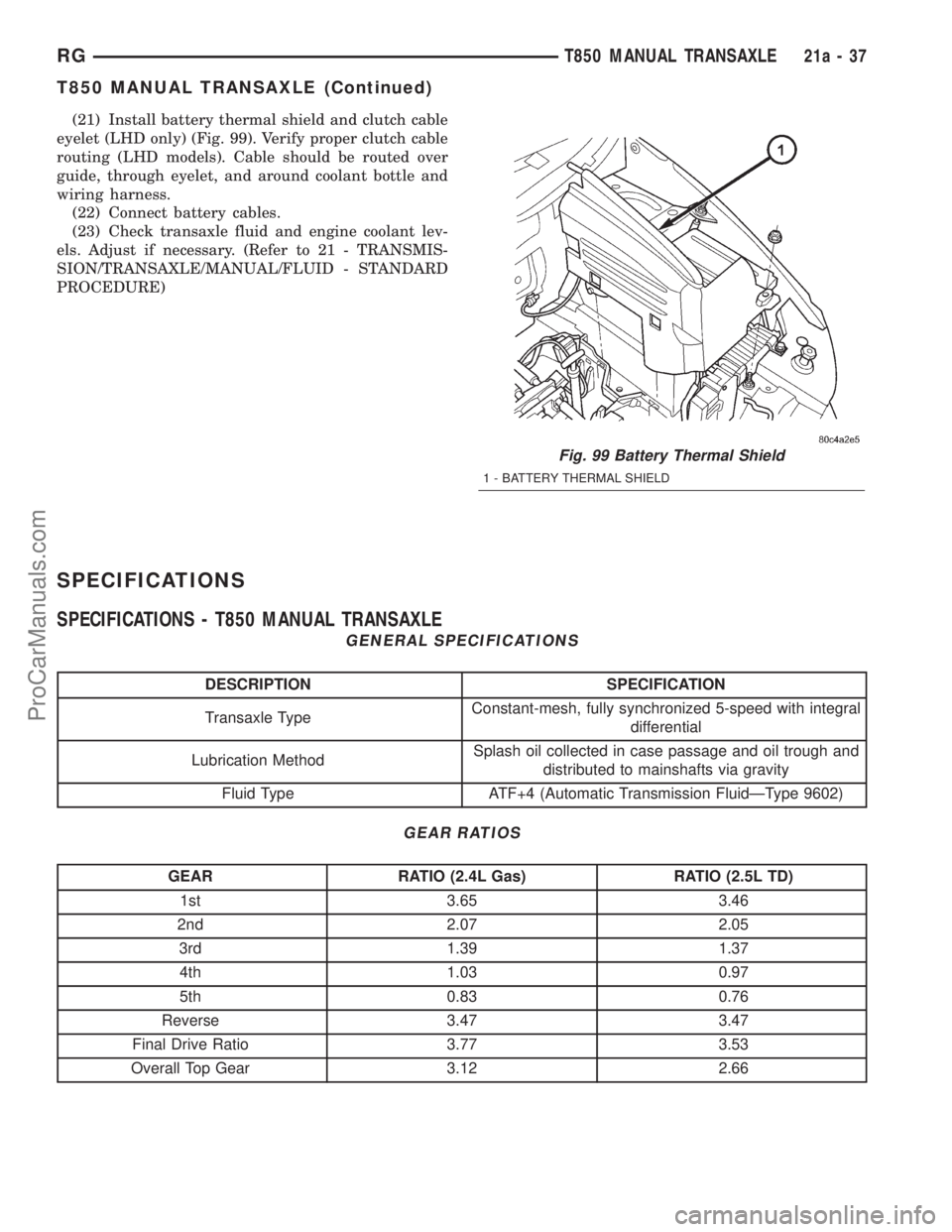
(21) Install battery thermal shield and clutch cable
eyelet (LHD only) (Fig. 99). Verify proper clutch cable
routing (LHD models). Cable should be routed over
guide, through eyelet, and around coolant bottle and
wiring harness.
(22) Connect battery cables.
(23) Check transaxle fluid and engine coolant lev-
els. Adjust if necessary. (Refer to 21 - TRANSMIS-
SION/TRANSAXLE/MANUAL/FLUID - STANDARD
PROCEDURE)
SPECIFICATIONS
SPECIFICATIONS - T850 MANUAL TRANSAXLE
GENERAL SPECIFICATIONS
DESCRIPTION SPECIFICATION
Transaxle TypeConstant-mesh, fully synchronized 5-speed with integral
differential
Lubrication MethodSplash oil collected in case passage and oil trough and
distributed to mainshafts via gravity
Fluid Type ATF+4 (Automatic Transmission FluidÐType 9602)
GEAR RATIOS
GEAR RATIO (2.4L Gas) RATIO (2.5L TD)
1st 3.65 3.46
2nd 2.07 2.05
3rd 1.39 1.37
4th 1.03 0.97
5th 0.83 0.76
Reverse 3.47 3.47
Final Drive Ratio 3.77 3.53
Overall Top Gear 3.12 2.66
Fig. 99 Battery Thermal Shield
1 - BATTERY THERMAL SHIELD
RGT850 MANUAL TRANSAXLE21a-37
T850 MANUAL TRANSAXLE (Continued)
ProCarManuals.com
Page 1853 of 2321
GEARSHIFT CABLE -
CROSSOVER
REMOVAL
(1) Disconnect battery negative cable.
(2) Remove gearshift knob by pushing down and
rotating ò-turn clock-wise (Fig. 139).(3) Remove gearshift boot from center console by
disengaging at three (3) retaining clips (Fig. 140).
(4) Apply park brake to allow park brake handle to
clear center console upon removal.
(5) Remove two (2) cupholder bottom plugs (Fig.
141).
(6) Remove four (4) center console-to-gearshift
mechanism screws. Remove console assembly (Fig.
142).
Fig. 138 Gearshift Boot Removal/Installation
1 - GEARSHIFT BOOT
2 - CENTER CONSOLE
Fig. 139 Gearshift Knob Removal/Installation
1 - GEARSHIFT KNOB
2 - GEARSHIFT LEVER
Fig. 140 Gearshift Boot Removal/Installation
1 - GEARSHIFT BOOT
2 - CENTER CONSOLE
Fig. 141 Cup Holder Plugs
1 - CUPHOLDER PLUG (2)
21a - 54 T850 MANUAL TRANSAXLERG
GEARSHIFT BOOT (Continued)
ProCarManuals.com
Page 1854 of 2321

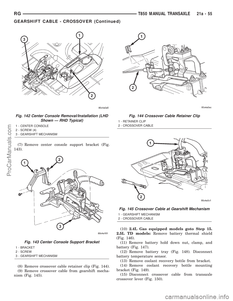
(7) Remove center console support bracket (Fig.
143).
(8) Remove crossover cable retainer clip (Fig. 144).
(9) Remove crossover cable from gearshift mecha-
nism (Fig. 145).(10)2.4L Gas equipped models goto Step 15.
2.5L TD models:Remove battery thermal shield
(Fig. 146).
(11) Remove battery hold down nut, clamp, and
battery (Fig. 147).
(12) Remove battery tray (Fig. 148). Disconnect
battery temperature sensor.
(13) Remove coolant recovery bottle from bracket.
(14) Remove coolant recovery bottle mounting
bracket (Fig. 149).
(15) Disconnect crossover cable from transaxle
crossover lever (Fig. 150).
Fig. 142 Center Console Removal/Installation (LHD
Shown Ð RHD Typical)
1 - CENTER CONSOLE
2 - SCREW (4)
3 - GEARSHIFT MECHANISM
Fig. 143 Center Console Support Bracket
1 - BRACKET
2 - SCREW
3 - GEARSHIFT MECHANISM
Fig. 144 Crossover Cable Retainer Clip
1 - RETAINER CLIP
2 - CROSSOVER CABLE
Fig. 145 Crossover Cable at Gearshift Mechanism
1 - GEARSHIFT MECHANISM
2 - CROSSOVER CABLE
RGT850 MANUAL TRANSAXLE21a-55
GEARSHIFT CABLE - CROSSOVER (Continued)
ProCarManuals.com