2001 DODGE TOWN AND COUNTRY battery
[x] Cancel search: batteryPage 2175 of 2321
OPERATION
Each blend door actuator is connected to the heat-
er-A/C control module through the vehicle electrical
system by a dedicated two-wire take out and connec-
tor of the HVAC wire harness. The blend door actua-
tor can move the blend air door in two directions.
When the heater-A/C control module pulls the volt-
age on one side of the motor connection high and the
other connection low, the blend air door will move in
one direction. When the module reverses the polarity
of the voltage to the motor, the blend air door moves
in the opposite direction. When the module makes
the voltage to both connections high or both connec-
tions low, the blend air door stops and will not move.
These same motor connections also provide a feed-
back signal to the heater-A/C control module. This
feedback signal allows the module to monitor the
operation and relative positions of the blend door
actuator and the blend air door. The heater-A/C con-
trol module learns the blend air door stop positions
during the calibration procedure and will store a
Diagnostic Trouble Code (DTC) for any problems it
detects in the blend door actuator circuits. The blend
door actuator can be diagnosed using a DRBIIItscan
tool. Refer to the appropriate diagnostic information.
REMOVAL
The single zone heating and air conditioning sys-
tem is equipped with a single blend door actuator.
The dual zone system has two blend door actuators,
one for the driver side blend air door and one for the
passenger side blend air door. The same service pro-
cedures can be used for each of these actuators.
WARNING: ON VEHICLES EQUIPPED WITH AIR-
BAGS, DISABLE THE AIRBAG SYSTEM BEFORE
ATTEMPTING ANY STEERING WHEEL, STEERING
COLUMN, OR INSTRUMENT PANEL COMPONENT
DIAGNOSIS OR SERVICE. DISCONNECT AND ISO-
LATE THE BATTERY NEGATIVE (GROUND) CABLE,
THEN WAIT TWO MINUTES FOR THE AIRBAG SYS-
TEM CAPACITOR TO DISCHARGE BEFORE PER-
FORMING FURTHER DIAGNOSIS OR SERVICE. THIS
IS THE ONLY SURE WAY TO DISABLE THE AIRBAG
SYSTEM. FAILURE TO TAKE THE PROPER PRE-
CAUTIONS COULD RESULT IN ACCIDENTAL AIR-
BAG DEPLOYMENT AND POSSIBLE PERSONAL
INJURY.
(1) Disconnect and isolate the battery negative
cable.
(2) Remove the silencer from beneath the driver
side end of the instrument panel. (Refer to 23 -
BODY/INSTRUMENT PANEL/INSTRUMENT
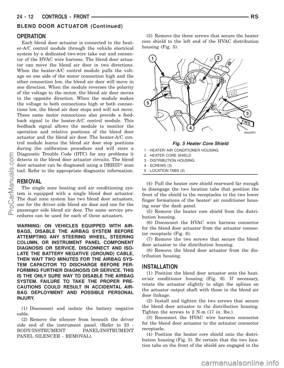
PANEL SILENCER - REMOVAL).(3) Remove the three screws that secure the heater
core shield to the left end of the HVAC distribution
housing (Fig. 5).
(4) Pull the heater core shield rearward far enough
to disengage the two location tabs that position the
front of the shield to the receptacles in the two lower
finger formations of the heater/ air conditioner hous-
ing near the dash panel.
(5) Remove the heater core shield from the distri-
bution housing.
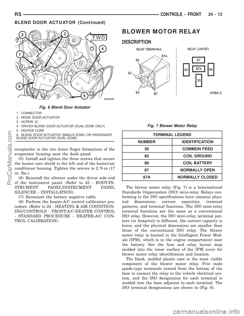
(6) Disconnect the HVAC wire harness connector
for the blend door actuator from the actuator connec-
tor receptacle (Fig. 6).
(7) Remove the two screws that secure the blend
door actuator to the distribution housing.
(8) Remove the blend door actuator from the dis-
tribution housing.
INSTALLATION
(1) Position the blend door actuator onto the heat-
er/air conditioner housing (Fig. 6). If necessary,
rotate the actuator slightly to align the splines on
the actuator output shaft with those in the blend air
door linkage.
(2) Install and tighten the two screws that secure
the blend door actuator to the distribution housing.
Tighten the screws to 2 N´m (17 in. lbs.).
(3) Reconnect the HVAC wire harness connector
for the blend door actuator to the actuator connector
receptacle.
(4) Position the heater core shield onto the distri-
bution housing (Fig. 5). Be certain that the two loca-
tion tabs on the front of the shield are engaged in the
Fig. 5 Heater Core Shield
1 - HEATER/ AIR CONDITIONER HOUSING
2 - HEATER CORE SHIELD
3 - DISTRIBUTION HOUSING
4 - SCREWS (3)
5 - LOCATION TABS (2)
24 - 12 CONTROLS - FRONTRS
BLEND DOOR ACTUATOR (Continued)
ProCarManuals.com
Page 2176 of 2321
receptacles in the two lower finger formations of the
evaporator housing near the dash panel.
(5) Install and tighten the three screws that secure
the heater core shield to the left end of the heater/air
conditioner housing. Tighten the screws to 2 N´m (17
in. lbs.).
(6) Reinstall the silencer under the driver side end
of the instrument panel. (Refer to 23 - BODY/IN-
STRUMENT PANEL/INSTRUMENT PANEL
SILENCER - INSTALLATION).
(7) Reconnect the battery negative cable.
(8) Perform the heater-A/C control calibration pro-
cedure. (Refer to 24 - HEATING & AIR CONDITION-
ING/CONTROLS - FRONT/A/C-HEATER CONTROL
- STANDARD PROCEDURE - HEATER-A/C CON-
TROL CALIBRATION).
BLOWER MOTOR RELAY
DESCRIPTION
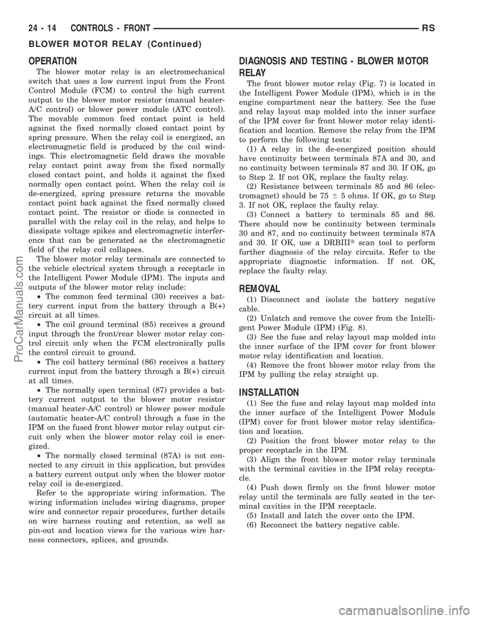
TERMINAL LEGEND
NUMBER IDENTIFICATION
30 COMMON FEED
85 COIL GROUND
86 COIL BATTERY
87 NORMALLY OPEN
87A NORMALLY CLOSED
The blower motor relay (Fig. 7) is a International
Standards Organization (ISO) mini-relay. Relays con-
forming to the ISO specifications have common phys-
ical dimensions, current capacities, terminal
patterns, and terminal functions. The ISO mini-relay
terminal functions are the same as a conventional
ISO relay. However, the ISO mini-relay terminal pat-
tern (or footprint) is different, the current capacity is
lower, and the physical dimensions are smaller than
those of the conventional ISO relay. The blower
motor relay is located in the Intelligent Power Mod-
ule (IPM), which is in the engine compartment near
the battery. See the fuse and relay layout map
molded into the inner surface of the IPM cover for
blower motor relay identification and location.
The black, molded plastic case is the most visible
component of the blower motor relay. Five male
spade-type terminals extend from the bottom of the
base to connect the relay to the vehicle electrical sys-
tem, and the ISO designation for each terminal is
molded into the base adjacent to each terminal. The
ISO terminal designations are shown in (Fig. 8).
Fig. 6 Blend Door Actuator
1 - CONNECTOR
2 - MODE DOOR ACTUATOR
3 - SCREW (2)
4 - DRIVER BLEND DOOR ACTUATOR (DUAL-ZONE ONLY)
5 - HEATER CORE
6 - BLEND DOOR ACTUATOR (SINGLE-ZONE) OR PASSENGER
BLEND DOOR ACTUATOR (DUAL-ZONE)
Fig. 7 Blower Motor Relay
RSCONTROLS - FRONT24-13
BLEND DOOR ACTUATOR (Continued)
ProCarManuals.com
Page 2177 of 2321
OPERATION
The blower motor relay is an electromechanical
switch that uses a low current input from the Front
Control Module (FCM) to control the high current
output to the blower motor resistor (manual heater-
A/C control) or blower power module (ATC control).
The movable common feed contact point is held
against the fixed normally closed contact point by
spring pressure. When the relay coil is energized, an
electromagnetic field is produced by the coil wind-
ings. This electromagnetic field draws the movable
relay contact point away from the fixed normally
closed contact point, and holds it against the fixed
normally open contact point. When the relay coil is
de-energized, spring pressure returns the movable
contact point back against the fixed normally closed
contact point. The resistor or diode is connected in
parallel with the relay coil in the relay, and helps to
dissipate voltage spikes and electromagnetic interfer-
ence that can be generated as the electromagnetic
field of the relay coil collapses.
The blower motor relay terminals are connected to
the vehicle electrical system through a receptacle in
the Intelligent Power Module (IPM). The inputs and
outputs of the blower motor relay include:
²The common feed terminal (30) receives a bat-
tery current input from the battery through a B(+)
circuit at all times.
²The coil ground terminal (85) receives a ground
input through the front/rear blower motor relay con-
trol circuit only when the FCM electronically pulls
the control circuit to ground.
²The coil battery terminal (86) receives a battery
current input from the battery through a B(+) circuit
at all times.
²The normally open terminal (87) provides a bat-
tery current output to the blower motor resistor
(manual heater-A/C control) or blower power module
(automatic heater-A/C control) through a fuse in the
IPM on the fused front blower motor relay output cir-
cuit only when the blower motor relay coil is ener-
gized.
²The normally closed terminal (87A) is not con-
nected to any circuit in this application, but provides
a battery current output only when the blower motor
relay coil is de-energized.
Refer to the appropriate wiring information. The
wiring information includes wiring diagrams, proper
wire and connector repair procedures, further details
on wire harness routing and retention, as well as
pin-out and location views for the various wire har-
ness connectors, splices, and grounds.
DIAGNOSIS AND TESTING - BLOWER MOTOR
RELAY
The front blower motor relay (Fig. 7) is located in
the Intelligent Power Module (IPM), which is in the
engine compartment near the battery. See the fuse
and relay layout map molded into the inner surface
of the IPM cover for front blower motor relay identi-
fication and location. Remove the relay from the IPM
to perform the following tests:
(1) A relay in the de-energized position should
have continuity between terminals 87A and 30, and
no continuity between terminals 87 and 30. If OK, go
to Step 2. If not OK, replace the faulty relay.
(2) Resistance between terminals 85 and 86 (elec-
tromagnet) should be 7565 ohms. If OK, go to Step
3. If not OK, replace the faulty relay.
(3) Connect a battery to terminals 85 and 86.
There should now be continuity between terminals
30 and 87, and no continuity between terminals 87A
and 30. If OK, use a DRBIIItscan tool to perform
further diagnosis of the relay circuits. Refer to the
appropriate diagnostic information. If not OK,
replace the faulty relay.
REMOVAL
(1) Disconnect and isolate the battery negative
cable.
(2) Unlatch and remove the cover from the Intelli-
gent Power Module (IPM) (Fig. 8).
(3) See the fuse and relay layout map molded into
the inner surface of the IPM cover for front blower
motor relay identification and location.
(4) Remove the front blower motor relay from the
IPM by pulling the relay straight up.
INSTALLATION
(1) See the fuse and relay layout map molded into
the inner surface of the Intelligent Power Module
(IPM) cover for front blower motor relay identifica-
tion and location.
(2) Position the front blower motor relay to the
proper receptacle in the IPM.
(3) Align the front blower motor relay terminals
with the terminal cavities in the IPM relay recepta-
cle.
(4) Push down firmly on the front blower motor
relay until the terminals are fully seated in the ter-
minal cavities in the IPM receptacle.
(5) Install and latch the cover onto the IPM.
(6) Reconnect the battery negative cable.
24 - 14 CONTROLS - FRONTRS
BLOWER MOTOR RELAY (Continued)
ProCarManuals.com
Page 2178 of 2321
BLOWER MOTOR RESISTOR
DESCRIPTION
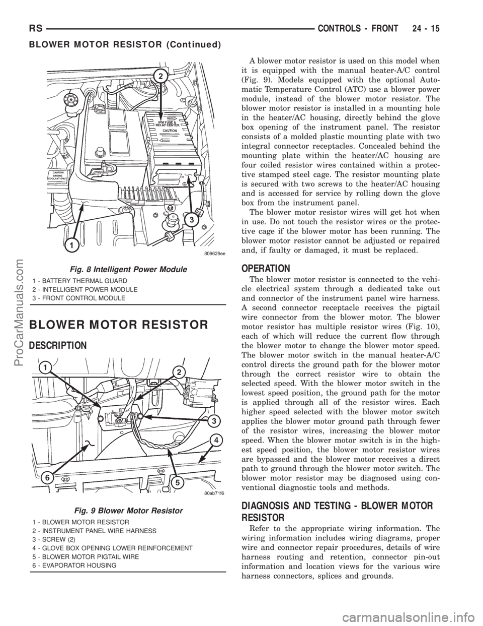
A blower motor resistor is used on this model when
it is equipped with the manual heater-A/C control
(Fig. 9). Models equipped with the optional Auto-
matic Temperature Control (ATC) use a blower power
module, instead of the blower motor resistor. The
blower motor resistor is installed in a mounting hole
in the heater/AC housing, directly behind the glove
box opening of the instrument panel. The resistor
consists of a molded plastic mounting plate with two
integral connector receptacles. Concealed behind the
mounting plate within the heater/AC housing are
four coiled resistor wires contained within a protec-
tive stamped steel cage. The resistor mounting plate
is secured with two screws to the heater/AC housing
and is accessed for service by rolling down the glove
box from the instrument panel.
The blower motor resistor wires will get hot when
in use. Do not touch the resistor wires or the protec-
tive cage if the blower motor has been running. The
blower motor resistor cannot be adjusted or repaired
and, if faulty or damaged, it must be replaced.
OPERATION
The blower motor resistor is connected to the vehi-
cle electrical system through a dedicated take out
and connector of the instrument panel wire harness.
A second connector receptacle receives the pigtail
wire connector from the blower motor. The blower
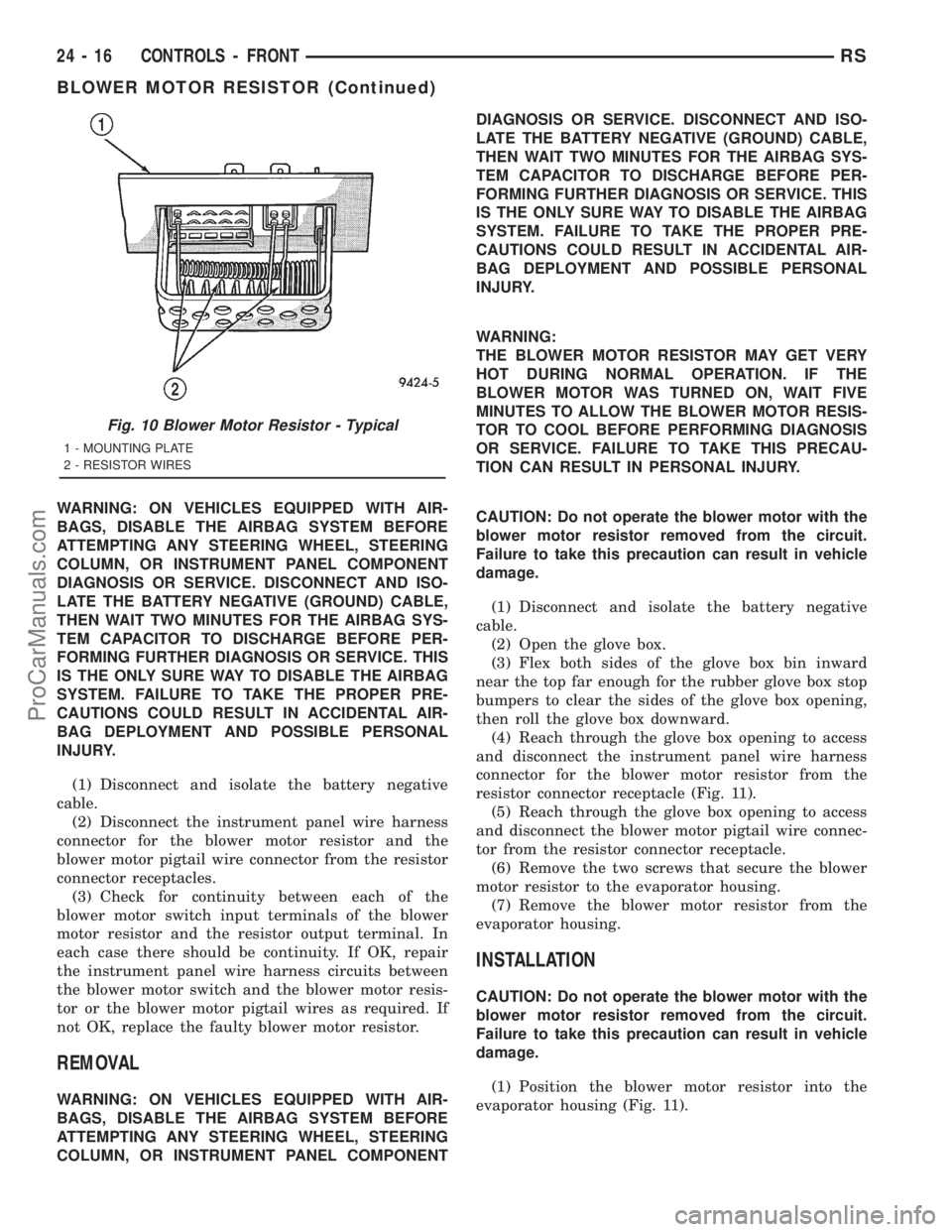
motor resistor has multiple resistor wires (Fig. 10),
each of which will reduce the current flow through
the blower motor to change the blower motor speed.
The blower motor switch in the manual heater-A/C
control directs the ground path for the blower motor
through the correct resistor wire to obtain the
selected speed. With the blower motor switch in the
lowest speed position, the ground path for the motor
is applied through all of the resistor wires. Each
higher speed selected with the blower motor switch
applies the blower motor ground path through fewer
of the resistor wires, increasing the blower motor
speed. When the blower motor switch is in the high-
est speed position, the blower motor resistor wires
are bypassed and the blower motor receives a direct
path to ground through the blower motor switch. The
blower motor resistor may be diagnosed using con-
ventional diagnostic tools and methods.
DIAGNOSIS AND TESTING - BLOWER MOTOR
RESISTOR
Refer to the appropriate wiring information. The
wiring information includes wiring diagrams, proper
wire and connector repair procedures, details of wire
harness routing and retention, connector pin-out
information and location views for the various wire
harness connectors, splices and grounds.
Fig. 8 Intelligent Power Module
1 - BATTERY THERMAL GUARD
2 - INTELLIGENT POWER MODULE
3 - FRONT CONTROL MODULE
Fig. 9 Blower Motor Resistor
1 - BLOWER MOTOR RESISTOR
2 - INSTRUMENT PANEL WIRE HARNESS
3 - SCREW (2)
4 - GLOVE BOX OPENING LOWER REINFORCEMENT
5 - BLOWER MOTOR PIGTAIL WIRE
6 - EVAPORATOR HOUSING
RSCONTROLS - FRONT24-15
BLOWER MOTOR RESISTOR (Continued)
ProCarManuals.com
Page 2179 of 2321
WARNING: ON VEHICLES EQUIPPED WITH AIR-
BAGS, DISABLE THE AIRBAG SYSTEM BEFORE
ATTEMPTING ANY STEERING WHEEL, STEERING
COLUMN, OR INSTRUMENT PANEL COMPONENT
DIAGNOSIS OR SERVICE. DISCONNECT AND ISO-
LATE THE BATTERY NEGATIVE (GROUND) CABLE,
THEN WAIT TWO MINUTES FOR THE AIRBAG SYS-
TEM CAPACITOR TO DISCHARGE BEFORE PER-
FORMING FURTHER DIAGNOSIS OR SERVICE. THIS
IS THE ONLY SURE WAY TO DISABLE THE AIRBAG
SYSTEM. FAILURE TO TAKE THE PROPER PRE-
CAUTIONS COULD RESULT IN ACCIDENTAL AIR-
BAG DEPLOYMENT AND POSSIBLE PERSONAL
INJURY.
(1) Disconnect and isolate the battery negative
cable.
(2) Disconnect the instrument panel wire harness
connector for the blower motor resistor and the
blower motor pigtail wire connector from the resistor
connector receptacles.
(3) Check for continuity between each of the
blower motor switch input terminals of the blower
motor resistor and the resistor output terminal. In
each case there should be continuity. If OK, repair
the instrument panel wire harness circuits between
the blower motor switch and the blower motor resis-
tor or the blower motor pigtail wires as required. If
not OK, replace the faulty blower motor resistor.
REMOVAL
WARNING: ON VEHICLES EQUIPPED WITH AIR-
BAGS, DISABLE THE AIRBAG SYSTEM BEFORE
ATTEMPTING ANY STEERING WHEEL, STEERING
COLUMN, OR INSTRUMENT PANEL COMPONENTDIAGNOSIS OR SERVICE. DISCONNECT AND ISO-
LATE THE BATTERY NEGATIVE (GROUND) CABLE,
THEN WAIT TWO MINUTES FOR THE AIRBAG SYS-
TEM CAPACITOR TO DISCHARGE BEFORE PER-
FORMING FURTHER DIAGNOSIS OR SERVICE. THIS
IS THE ONLY SURE WAY TO DISABLE THE AIRBAG
SYSTEM. FAILURE TO TAKE THE PROPER PRE-
CAUTIONS COULD RESULT IN ACCIDENTAL AIR-
BAG DEPLOYMENT AND POSSIBLE PERSONAL
INJURY.
WARNING:
THE BLOWER MOTOR RESISTOR MAY GET VERY
HOT DURING NORMAL OPERATION. IF THE
BLOWER MOTOR WAS TURNED ON, WAIT FIVE
MINUTES TO ALLOW THE BLOWER MOTOR RESIS-
TOR TO COOL BEFORE PERFORMING DIAGNOSIS
OR SERVICE. FAILURE TO TAKE THIS PRECAU-
TION CAN RESULT IN PERSONAL INJURY.
CAUTION: Do not operate the blower motor with the
blower motor resistor removed from the circuit.
Failure to take this precaution can result in vehicle
damage.
(1) Disconnect and isolate the battery negative
cable.
(2) Open the glove box.
(3) Flex both sides of the glove box bin inward
near the top far enough for the rubber glove box stop
bumpers to clear the sides of the glove box opening,
then roll the glove box downward.
(4) Reach through the glove box opening to access
and disconnect the instrument panel wire harness
connector for the blower motor resistor from the
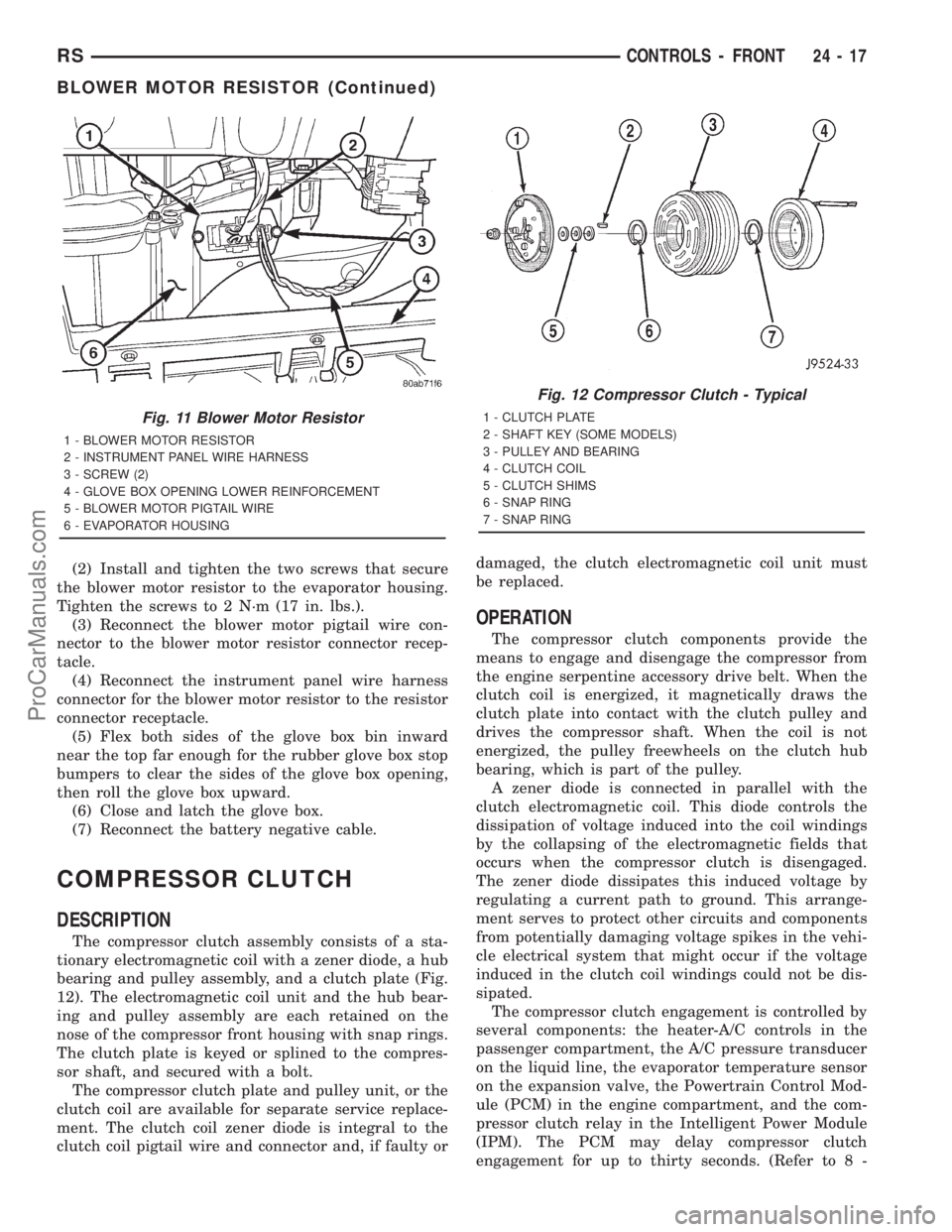
resistor connector receptacle (Fig. 11).
(5) Reach through the glove box opening to access
and disconnect the blower motor pigtail wire connec-
tor from the resistor connector receptacle.
(6) Remove the two screws that secure the blower
motor resistor to the evaporator housing.
(7) Remove the blower motor resistor from the
evaporator housing.
INSTALLATION
CAUTION: Do not operate the blower motor with the
blower motor resistor removed from the circuit.
Failure to take this precaution can result in vehicle
damage.
(1) Position the blower motor resistor into the
evaporator housing (Fig. 11).
Fig. 10 Blower Motor Resistor - Typical
1 - MOUNTING PLATE
2 - RESISTOR WIRES
24 - 16 CONTROLS - FRONTRS
BLOWER MOTOR RESISTOR (Continued)
ProCarManuals.com
Page 2180 of 2321
(2) Install and tighten the two screws that secure
the blower motor resistor to the evaporator housing.
Tighten the screws to 2 N´m (17 in. lbs.).
(3) Reconnect the blower motor pigtail wire con-
nector to the blower motor resistor connector recep-
tacle.
(4) Reconnect the instrument panel wire harness
connector for the blower motor resistor to the resistor
connector receptacle.
(5) Flex both sides of the glove box bin inward
near the top far enough for the rubber glove box stop
bumpers to clear the sides of the glove box opening,
then roll the glove box upward.
(6) Close and latch the glove box.
(7) Reconnect the battery negative cable.
COMPRESSOR CLUTCH
DESCRIPTION
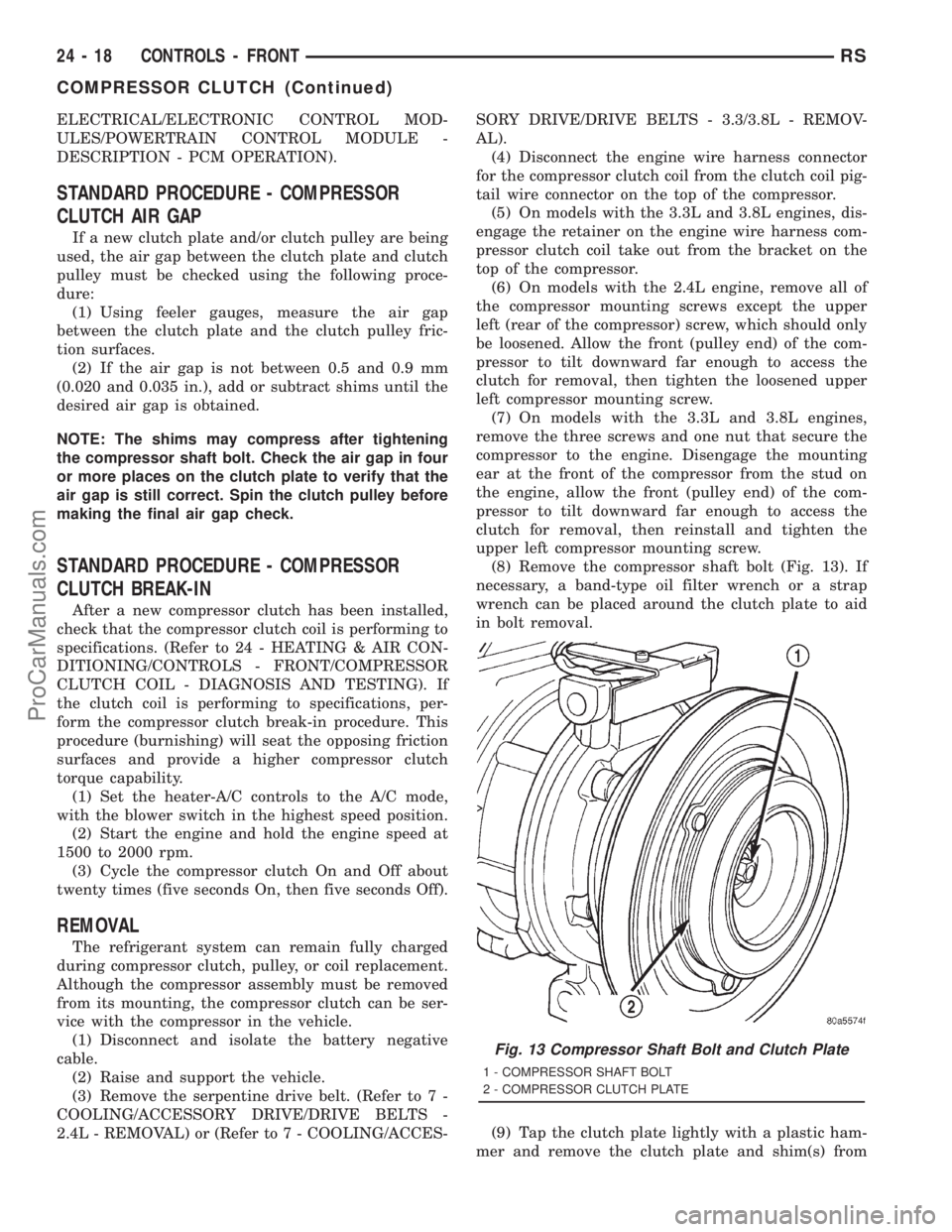
The compressor clutch assembly consists of a sta-
tionary electromagnetic coil with a zener diode, a hub
bearing and pulley assembly, and a clutch plate (Fig.
12). The electromagnetic coil unit and the hub bear-
ing and pulley assembly are each retained on the
nose of the compressor front housing with snap rings.
The clutch plate is keyed or splined to the compres-
sor shaft, and secured with a bolt.
The compressor clutch plate and pulley unit, or the
clutch coil are available for separate service replace-
ment. The clutch coil zener diode is integral to the
clutch coil pigtail wire and connector and, if faulty ordamaged, the clutch electromagnetic coil unit must
be replaced.
OPERATION
The compressor clutch components provide the
means to engage and disengage the compressor from
the engine serpentine accessory drive belt. When the
clutch coil is energized, it magnetically draws the
clutch plate into contact with the clutch pulley and
drives the compressor shaft. When the coil is not
energized, the pulley freewheels on the clutch hub
bearing, which is part of the pulley.
A zener diode is connected in parallel with the
clutch electromagnetic coil. This diode controls the
dissipation of voltage induced into the coil windings
by the collapsing of the electromagnetic fields that
occurs when the compressor clutch is disengaged.
The zener diode dissipates this induced voltage by
regulating a current path to ground. This arrange-
ment serves to protect other circuits and components
from potentially damaging voltage spikes in the vehi-
cle electrical system that might occur if the voltage
induced in the clutch coil windings could not be dis-
sipated.
The compressor clutch engagement is controlled by
several components: the heater-A/C controls in the
passenger compartment, the A/C pressure transducer
on the liquid line, the evaporator temperature sensor
on the expansion valve, the Powertrain Control Mod-
ule (PCM) in the engine compartment, and the com-
pressor clutch relay in the Intelligent Power Module
(IPM). The PCM may delay compressor clutch
engagement for up to thirty seconds. (Refer to 8 -
Fig. 11 Blower Motor Resistor
1 - BLOWER MOTOR RESISTOR
2 - INSTRUMENT PANEL WIRE HARNESS
3 - SCREW (2)
4 - GLOVE BOX OPENING LOWER REINFORCEMENT
5 - BLOWER MOTOR PIGTAIL WIRE
6 - EVAPORATOR HOUSING
Fig. 12 Compressor Clutch - Typical
1 - CLUTCH PLATE
2 - SHAFT KEY (SOME MODELS)
3 - PULLEY AND BEARING
4 - CLUTCH COIL
5 - CLUTCH SHIMS
6 - SNAP RING
7 - SNAP RING
RSCONTROLS - FRONT24-17
BLOWER MOTOR RESISTOR (Continued)
ProCarManuals.com
Page 2181 of 2321
ELECTRICAL/ELECTRONIC CONTROL MOD-
ULES/POWERTRAIN CONTROL MODULE -
DESCRIPTION - PCM OPERATION).
STANDARD PROCEDURE - COMPRESSOR
CLUTCH AIR GAP
If a new clutch plate and/or clutch pulley are being
used, the air gap between the clutch plate and clutch
pulley must be checked using the following proce-
dure:
(1) Using feeler gauges, measure the air gap
between the clutch plate and the clutch pulley fric-
tion surfaces.
(2) If the air gap is not between 0.5 and 0.9 mm
(0.020 and 0.035 in.), add or subtract shims until the
desired air gap is obtained.
NOTE: The shims may compress after tightening
the compressor shaft bolt. Check the air gap in four
or more places on the clutch plate to verify that the
air gap is still correct. Spin the clutch pulley before
making the final air gap check.
STANDARD PROCEDURE - COMPRESSOR
CLUTCH BREAK-IN
After a new compressor clutch has been installed,
check that the compressor clutch coil is performing to
specifications. (Refer to 24 - HEATING & AIR CON-
DITIONING/CONTROLS - FRONT/COMPRESSOR
CLUTCH COIL - DIAGNOSIS AND TESTING). If
the clutch coil is performing to specifications, per-
form the compressor clutch break-in procedure. This
procedure (burnishing) will seat the opposing friction
surfaces and provide a higher compressor clutch
torque capability.
(1) Set the heater-A/C controls to the A/C mode,
with the blower switch in the highest speed position.
(2) Start the engine and hold the engine speed at
1500 to 2000 rpm.
(3) Cycle the compressor clutch On and Off about
twenty times (five seconds On, then five seconds Off).
REMOVAL
The refrigerant system can remain fully charged
during compressor clutch, pulley, or coil replacement.
Although the compressor assembly must be removed
from its mounting, the compressor clutch can be ser-
vice with the compressor in the vehicle.
(1) Disconnect and isolate the battery negative
cable.
(2) Raise and support the vehicle.
(3) Remove the serpentine drive belt. (Refer to 7 -
COOLING/ACCESSORY DRIVE/DRIVE BELTS -
2.4L - REMOVAL) or (Refer to 7 - COOLING/ACCES-SORY DRIVE/DRIVE BELTS - 3.3/3.8L - REMOV-
AL).
(4) Disconnect the engine wire harness connector
for the compressor clutch coil from the clutch coil pig-
tail wire connector on the top of the compressor.
(5) On models with the 3.3L and 3.8L engines, dis-
engage the retainer on the engine wire harness com-
pressor clutch coil take out from the bracket on the
top of the compressor.
(6) On models with the 2.4L engine, remove all of
the compressor mounting screws except the upper
left (rear of the compressor) screw, which should only
be loosened. Allow the front (pulley end) of the com-
pressor to tilt downward far enough to access the
clutch for removal, then tighten the loosened upper
left compressor mounting screw.
(7) On models with the 3.3L and 3.8L engines,
remove the three screws and one nut that secure the
compressor to the engine. Disengage the mounting
ear at the front of the compressor from the stud on
the engine, allow the front (pulley end) of the com-
pressor to tilt downward far enough to access the
clutch for removal, then reinstall and tighten the
upper left compressor mounting screw.
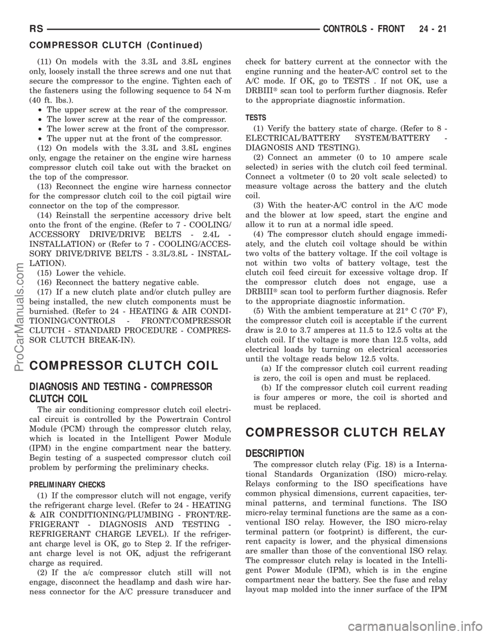
(8) Remove the compressor shaft bolt (Fig. 13). If
necessary, a band-type oil filter wrench or a strap
wrench can be placed around the clutch plate to aid
in bolt removal.
(9) Tap the clutch plate lightly with a plastic ham-
mer and remove the clutch plate and shim(s) from
Fig. 13 Compressor Shaft Bolt and Clutch Plate
1 - COMPRESSOR SHAFT BOLT
2 - COMPRESSOR CLUTCH PLATE
24 - 18 CONTROLS - FRONTRS
COMPRESSOR CLUTCH (Continued)
ProCarManuals.com
Page 2184 of 2321
(11) On models with the 3.3L and 3.8L engines
only, loosely install the three screws and one nut that
secure the compressor to the engine. Tighten each of
the fasteners using the following sequence to 54 N´m
(40 ft. lbs.).
²The upper screw at the rear of the compressor.
²The lower screw at the rear of the compressor.
²The lower screw at the front of the compressor.
²The upper nut at the front of the compressor.
(12) On models with the 3.3L and 3.8L engines
only, engage the retainer on the engine wire harness
compressor clutch coil take out with the bracket on
the top of the compressor.
(13) Reconnect the engine wire harness connector
for the compressor clutch coil to the coil pigtail wire
connector on the top of the compressor.
(14) Reinstall the serpentine accessory drive belt
onto the front of the engine. (Refer to 7 - COOLING/
ACCESSORY DRIVE/DRIVE BELTS - 2.4L -
INSTALLATION) or (Refer to 7 - COOLING/ACCES-
SORY DRIVE/DRIVE BELTS - 3.3L/3.8L - INSTAL-
LATION).
(15) Lower the vehicle.
(16) Reconnect the battery negative cable.
(17) If a new clutch plate and/or clutch pulley are
being installed, the new clutch components must be
burnished. (Refer to 24 - HEATING & AIR CONDI-
TIONING/CONTROLS - FRONT/COMPRESSOR
CLUTCH - STANDARD PROCEDURE - COMPRES-
SOR CLUTCH BREAK-IN).
COMPRESSOR CLUTCH COIL
DIAGNOSIS AND TESTING - COMPRESSOR
CLUTCH COIL
The air conditioning compressor clutch coil electri-
cal circuit is controlled by the Powertrain Control
Module (PCM) through the compressor clutch relay,
which is located in the Intelligent Power Module
(IPM) in the engine compartment near the battery.
Begin testing of a suspected compressor clutch coil
problem by performing the preliminary checks.
PRELIMINARY CHECKS
(1) If the compressor clutch will not engage, verify
the refrigerant charge level. (Refer to 24 - HEATING
& AIR CONDITIONING/PLUMBING - FRONT/RE-
FRIGERANT - DIAGNOSIS AND TESTING -
REFRIGERANT CHARGE LEVEL). If the refriger-
ant charge level is OK, go to Step 2. If the refriger-
ant charge level is not OK, adjust the refrigerant
charge as required.
(2) If the a/c compressor clutch still will not
engage, disconnect the headlamp and dash wire har-
ness connector for the A/C pressure transducer andcheck for battery current at the connector with the
engine running and the heater-A/C control set to the
A/C mode. If OK, go to TESTS . If not OK, use a
DRBIIItscan tool to perform further diagnosis. Refer
to the appropriate diagnostic information.
TESTS
(1) Verify the battery state of charge. (Refer to 8 -
ELECTRICAL/BATTERY SYSTEM/BATTERY -
DIAGNOSIS AND TESTING).
(2) Connect an ammeter (0 to 10 ampere scale
selected) in series with the clutch coil feed terminal.
Connect a voltmeter (0 to 20 volt scale selected) to
measure voltage across the battery and the clutch
coil.
(3) With the heater-A/C control in the A/C mode
and the blower at low speed, start the engine and
allow it to run at a normal idle speed.
(4) The compressor clutch should engage immedi-
ately, and the clutch coil voltage should be within
two volts of the battery voltage. If the coil voltage is
not within two volts of battery voltage, test the
clutch coil feed circuit for excessive voltage drop. If
the compressor clutch does not engage, use a
DRBIIItscan tool to perform further diagnosis. Refer
to the appropriate diagnostic information.
(5) With the ambient temperature at 21É C (70É F),
the compressor clutch coil is acceptable if the current
draw is 2.0 to 3.7 amperes at 11.5 to 12.5 volts at the
clutch coil. If the voltage is more than 12.5 volts, add
electrical loads by turning on electrical accessories
until the voltage reads below 12.5 volts.
(a) If the compressor clutch coil current reading
is zero, the coil is open and must be replaced.
(b) If the compressor clutch coil current reading
is four amperes or more, the coil is shorted and
must be replaced.
COMPRESSOR CLUTCH RELAY
DESCRIPTION
The compressor clutch relay (Fig. 18) is a Interna-
tional Standards Organization (ISO) micro-relay.
Relays conforming to the ISO specifications have
common physical dimensions, current capacities, ter-
minal patterns, and terminal functions. The ISO
micro-relay terminal functions are the same as a con-
ventional ISO relay. However, the ISO micro-relay
terminal pattern (or footprint) is different, the cur-
rent capacity is lower, and the physical dimensions
are smaller than those of the conventional ISO relay.
The compressor clutch relay is located in the Intelli-
gent Power Module (IPM), which is in the engine
compartment near the battery. See the fuse and relay
layout map molded into the inner surface of the IPM
RSCONTROLS - FRONT24-21
COMPRESSOR CLUTCH (Continued)
ProCarManuals.com