2001 DODGE TOWN AND COUNTRY battery
[x] Cancel search: batteryPage 1864 of 2321
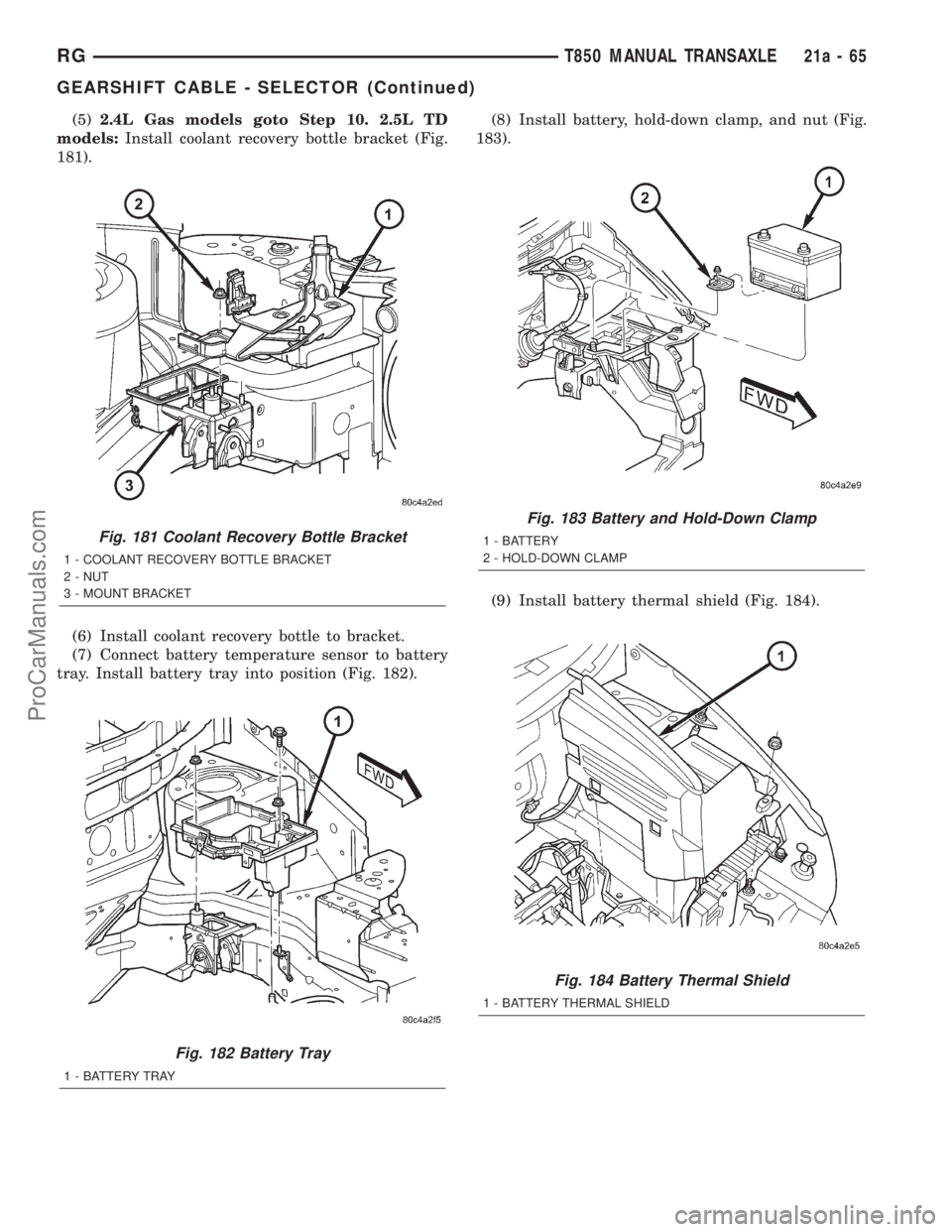
(5)2.4L Gas models goto Step 10. 2.5L TD
models:Install coolant recovery bottle bracket (Fig.
181).
(6) Install coolant recovery bottle to bracket.
(7) Connect battery temperature sensor to battery
tray. Install battery tray into position (Fig. 182).(8) Install battery, hold-down clamp, and nut (Fig.
183).
(9) Install battery thermal shield (Fig. 184).
Fig. 181 Coolant Recovery Bottle Bracket
1 - COOLANT RECOVERY BOTTLE BRACKET
2 - NUT
3 - MOUNT BRACKET
Fig. 182 Battery Tray
1 - BATTERY TRAY
Fig. 183 Battery and Hold-Down Clamp
1 - BATTERY
2 - HOLD-DOWN CLAMP
Fig. 184 Battery Thermal Shield
1 - BATTERY THERMAL SHIELD
RGT850 MANUAL TRANSAXLE21a-65
GEARSHIFT CABLE - SELECTOR (Continued)
ProCarManuals.com
Page 1866 of 2321
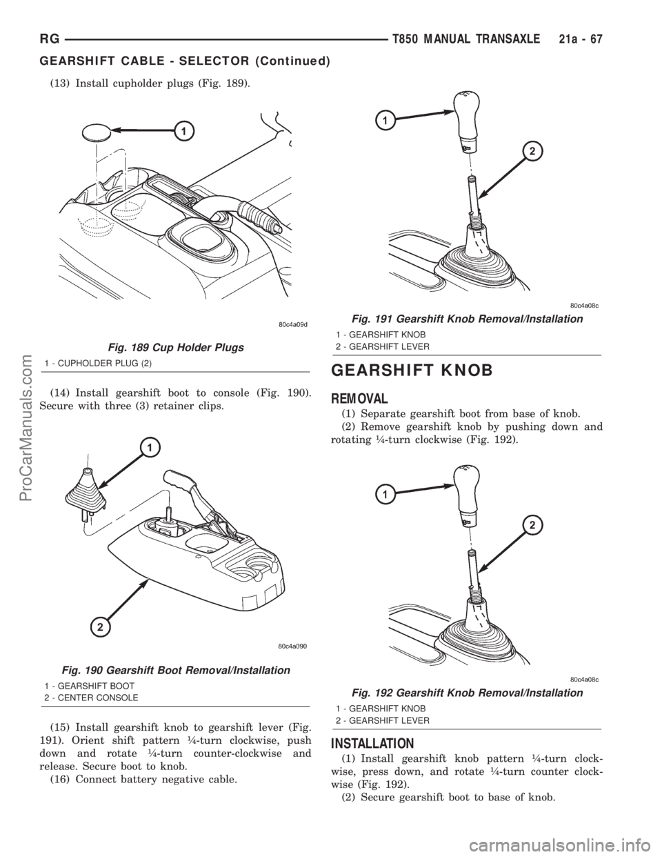
(13) Install cupholder plugs (Fig. 189).
(14) Install gearshift boot to console (Fig. 190).
Secure with three (3) retainer clips.
(15) Install gearshift knob to gearshift lever (Fig.
191). Orient shift pattern ò-turn clockwise, push
down and rotate ò-turn counter-clockwise and
release. Secure boot to knob.
(16) Connect battery negative cable.
GEARSHIFT KNOB
REMOVAL
(1) Separate gearshift boot from base of knob.
(2) Remove gearshift knob by pushing down and
rotating ò-turn clockwise (Fig. 192).
INSTALLATION
(1) Install gearshift knob pattern ò-turn clock-
wise, press down, and rotate ò-turn counter clock-
wise (Fig. 192).
(2) Secure gearshift boot to base of knob.
Fig. 189 Cup Holder Plugs
1 - CUPHOLDER PLUG (2)
Fig. 190 Gearshift Boot Removal/Installation
1 - GEARSHIFT BOOT
2 - CENTER CONSOLE
Fig. 191 Gearshift Knob Removal/Installation
1 - GEARSHIFT KNOB
2 - GEARSHIFT LEVER
Fig. 192 Gearshift Knob Removal/Installation
1 - GEARSHIFT KNOB
2 - GEARSHIFT LEVER
RGT850 MANUAL TRANSAXLE21a-67
GEARSHIFT CABLE - SELECTOR (Continued)
ProCarManuals.com
Page 1867 of 2321
GEARSHIFT MECHANISM
REMOVAL
(1) Disconnect battery negative cable.
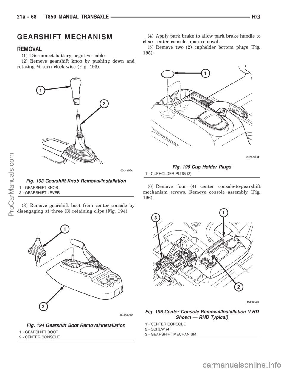
(2) Remove gearshift knob by pushing down and
rotating ò turn clock-wise (Fig. 193).
(3) Remove gearshift boot from center console by
disengaging at three (3) retaining clips (Fig. 194).(4) Apply park brake to allow park brake handle to
clear center console upon removal.
(5) Remove two (2) cupholder bottom plugs (Fig.
195).
(6) Remove four (4) center console-to-gearshift
mechanism screws. Remove console assembly (Fig.
196).
Fig. 193 Gearshift Knob Removal/Installation
1 - GEARSHIFT KNOB
2 - GEARSHIFT LEVER
Fig. 194 Gearshift Boot Removal/Installation
1 - GEARSHIFT BOOT
2 - CENTER CONSOLE
Fig. 195 Cup Holder Plugs
1 - CUPHOLDER PLUG (2)
Fig. 196 Center Console Removal/Installation (LHD
Shown Ð RHD Typical)
1 - CENTER CONSOLE
2 - SCREW (4)
3 - GEARSHIFT MECHANISM
21a - 68 T850 MANUAL TRANSAXLERG
ProCarManuals.com
Page 1871 of 2321
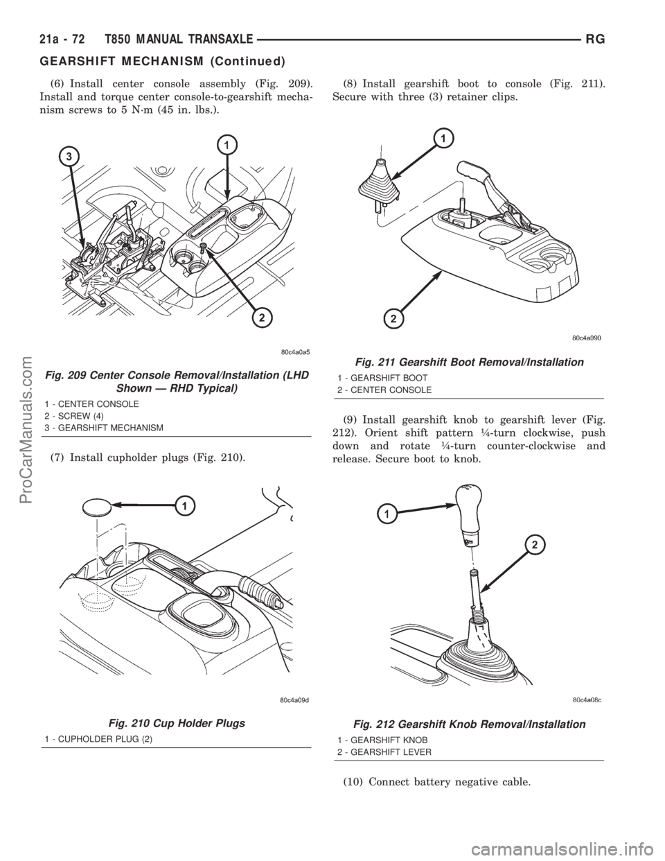
(6) Install center console assembly (Fig. 209).
Install and torque center console-to-gearshift mecha-
nism screws to 5 N´m (45 in. lbs.).
(7) Install cupholder plugs (Fig. 210).(8) Install gearshift boot to console (Fig. 211).
Secure with three (3) retainer clips.
(9) Install gearshift knob to gearshift lever (Fig.
212). Orient shift pattern ò-turn clockwise, push
down and rotate ò-turn counter-clockwise and
release. Secure boot to knob.
(10) Connect battery negative cable.
Fig. 209 Center Console Removal/Installation (LHD
Shown Ð RHD Typical)
1 - CENTER CONSOLE
2 - SCREW (4)
3 - GEARSHIFT MECHANISM
Fig. 210 Cup Holder Plugs
1 - CUPHOLDER PLUG (2)
Fig. 211 Gearshift Boot Removal/Installation
1 - GEARSHIFT BOOT
2 - CENTER CONSOLE
Fig. 212 Gearshift Knob Removal/Installation
1 - GEARSHIFT KNOB
2 - GEARSHIFT LEVER
21a - 72 T850 MANUAL TRANSAXLERG
GEARSHIFT MECHANISM (Continued)
ProCarManuals.com
Page 1915 of 2321
Before removing the glass, check the availability of
replacement components.
SEATS
Seat modules are made up of a seat frame, seat
cushion, seat back cushion, a covering material, and
the electrical components used for power operation, if
equipped. Some seat systems also contain seat belt
components and supplemental restraint systems.
Seat assemblies transport the occupants in comfort
and safety. Seat assemblies also help position occu-
pants correctly in the event of airbag deployment.
Seat cushions, coverings, and electrical components
are serviceable. Refer to the appropriate group in
this manual.
EXTERIOR COMPONENTS
Exterior sheet metal components make up the
exterior of the vehicle. Some exterior metal systems
are welded assemblies, such as doors and hoods.
Some exterior trim items are made of composite.
The exterior is finished in various metal stampings
and composite moldings. These assemblies give the
vehicle a finished appearance and protect the occu-
pants from the elements. Some components are part
of the energy absorbing system used to protect the
occupants in collisions. The exterior sheet metal is
repairable and adjustable for fit and finish. Welded
and bonded component systems are adjustable as a
system. Trim components made of composite are
stamped with the type of material used.
DaimlerChrysler uses various fasteners to retain
trim items. At times, it is not possible to remove trim
items without damaging the fastener. If it is not pos-
sible to remove an item without damaging a compo-
nent, cut or break the fasteners and use new ones
when installing the component.
SAFETY PRECAUTIONS AND WARNINGS
WARNING:
EYE PROTECTION SHOULD BE USED WHEN SER-
VICING GLASS COMPONENTS. PERSONAL INJURY
CAN RESULT.
USE A OSHA APPROVED BREATHING FILTER
WHEN SPRAYING PAINT OR SOLVENTS IN A CON-
FINED AREA. PERSONAL INJURY CAN RESULT.
AVOID PROLONGED SKIN CONTACT WITH PETRO-
LEUM OR ALCOHOL BASED CLEANING SOLVENTS.
PERSONAL INJURY CAN RESULT.
DO NOT STAND UNDER A HOISTED VEHICLE THAT
IS NOT PROPERLY SUPPORTED ON SAFETY
STANDS. PERSONAL INJURY CAN RESULT.
CAUTION:
When holes must be drilled or punched in an innerbody panel, verify depth of space to the outer body
panel, electrical wiring, or other components. Dam-
age to vehicle can result.
Do not weld exterior panels unless combustible
material on the interior of vehicle is removed from
the repair area. Fire or hazardous conditions, can
result.
Always have a fire extinguisher ready for use when
welding.
Disconnect the negative battery cable clamp when
servicing electrical components that are live when
the ignition is OFF. Damage to electrical system can
result.
Do not use abrasive chemicals or compounds on
painted surfaces. Damage to finish can result.
Do not use harsh alkaline based cleaning solvents
on painted or upholstered surfaces. Damage to fin-
ish or color can result.
Do not hammer or pound on plastic trim panel
when servicing interior trim. Plastic panels can
break.
DIAGNOSIS AND TESTING - WATER LEAKS
Water leaks can be caused by poor sealing,
improper body component alignment, body seam
porosity, missing plugs, or blocked drain holes. Cen-
trifugal and gravitational force can cause water to
drip from a location away from the actual leak point,
making leak detection difficult. All body sealing
points should be water tight in normal wet-driving
conditions. Water flowing downward from the front of
the vehicle should not enter the passenger or luggage
compartment. Moving sealing surfaces will not
always seal water tight under all conditions. At
times, side glass or door seals will allow water to
enter the passenger compartment during high pres-
sure washing or hard driving rain (severe) condi-
tions. Overcompensating on door or glass
adjustments to stop a water leak that occurs under
severe conditions can cause premature seal wear and
excessive closing or latching effort. After completing
a repair, water test vehicle to verify leak has stopped
before returning vehicle to use.
VISUAL INSPECTION BEFORE WATER LEAK TESTS
Verify that floor and body plugs are in place, body
drains are clear, and body components are properly
aligned and sealed. If component alignment or seal-
ing is necessary, refer to the appropriate section of
this group for proper procedures.
WATER LEAK TESTS
WARNING: DO NOT USE ELECTRIC SHOP LIGHTS
OR TOOLS IN WATER TEST AREA. PERSONAL
INJURY CAN RESULT.
23 - 2 BODYRS
BODY (Continued)
ProCarManuals.com
Page 1916 of 2321
When the conditions causing a water leak have
been determined, simulate the conditions as closely
as possible.
²If a leak occurs with the vehicle parked in a
steady light rain, flood the leak area with an open-
ended garden hose.
²If a leak occurs while driving at highway speeds
in a steady rain, test the leak area with a reasonable
velocity stream or fan spray of water. Direct the
spray in a direction comparable to actual conditions.
²If a leak occurs when the vehicle is parked on an
incline, hoist the end or side of the vehicle to simu-
late this condition. This method can be used when
the leak occurs when the vehicle accelerates, stops or
turns. If the leak occurs on acceleration, hoist the
front of the vehicle. If the leak occurs when braking,
hoist the back of the vehicle. If the leak occurs on left
turns, hoist the left side of the vehicle. If the leak
occurs on right turns, hoist the right side of the vehi-
cle. For hoisting recommendations refer to Group 0,
Lubrication and Maintenance, General Information
section.
WATER LEAK DETECTION
To detect a water leak point-of-entry, do a water
test and watch for water tracks or droplets forming
on the inside of the vehicle. If necessary, remove inte-
rior trim covers or panels to gain visual access to the
leak area. If the hose cannot be positioned without
being held, have someone help do the water test.
Some water leaks must be tested for a considerable
length of time to become apparent. When a leak
appears, find the highest point of the water track or
drop. The highest point usually will show the point of
entry. After leak point has been found, repair the
leak and water test to verify that the leak has
stopped.
Locating the entry point of water that is leaking
into a cavity between panels can be difficult. The
trapped water may splash or run from the cavity,
often at a distance from the entry point. Most water
leaks of this type become apparent after accelerating,
stopping, turning, or when on an incline.
MIRROR INSPECTION METHOD
When a leak point area is visually obstructed, use
a suitable mirror to gain visual access. A mirror can
also be used to deflect light to a limited-access area
to assist in locating a leak point.
BRIGHT LIGHT LEAK TEST METHOD
Some water leaks in the luggage compartment can
be detected without water testing. Position the vehi-
cle in a brightly lit area. From inside the darkened
luggage compartment inspect around seals and body
seams. If necessary, have a helper direct a drop lightover the suspected leak areas around the luggage
compartment. If light is visible through a normally
sealed location, water could enter through the open-
ing.
PRESSURIZED LEAK TEST METHOD
When a water leak into the passenger compart-
ment cannot be detected by water testing, pressurize
the passenger compartment and soap test exterior of
the vehicle. To pressurize the passenger compart-
ment, close all doors and windows, start engine, and
set heater control to high blower in HEAT position. If
engine can not be started, connect a charger to the
battery to ensure adequate voltage to the blower.
With interior pressurized, apply dish detergent solu-
tion to suspected leak area on the exterior of the
vehicle. Apply detergent solution with spray device or
soft bristle brush. If soap bubbles occur at a body
seam, joint, seal or gasket, the leak entry point could
be at that location.
DIAGNOSIS AND TESTING - WIND NOISE
Wind noise is the result of most air leaks. Air leaks
can be caused by poor sealing, improper body compo-
nent alignment, body seam porosity, or missing plugs
in the engine compartment or door hinge pillar areas.
All body sealing points should be airtight in normal
driving conditions. Moving sealing surfaces will not
always seal airtight under all conditions. At times,
side glass or door seals will allow wind noise to be
noticed in the passenger compartment during high
cross winds. Over compensating on door or glass
adjustments to stop wind noise that occurs under
severe conditions can cause premature seal wear and
excessive closing or latching effort. After a repair pro-
cedure has been performed, test vehicle to verify
noise has stopped before returning vehicle to use.
Wind noise can also be caused by improperly fitted
exterior moldings or body ornamentation. Loose
moldings can flutter, creating a buzzing or chattering
noise. An open cavity or protruding edge can create a
whistling or howling noise. Inspect the exterior of the
vehicle to verify that these conditions do not exist.
VISUAL INSPECTION BEFORE TESTS
Verify that floor and body plugs are in place and
body components are aligned and sealed. If compo-
nent alignment or sealing is necessary, refer to the
appropriate section of this group for proper proce-
dures.
ROAD TESTING WIND NOISE
(1) Drive the vehicle to verify the general location
of the wind noise.
(2) Apply 50 mm (2 in.) masking tape in 150 mm
(6 in.) lengths along weatherstrips, weld seams or
RSBODY23-3
BODY (Continued)
ProCarManuals.com
Page 2090 of 2321
(5) Engage rigging cam to latch/lock control mech-
anism.
(6) Move clip on latch/lock control to bottom of slot
and engage linkage to latch/lock control.
(7) Verify sliding door operation. Adjust as neces-
sary.
(8) Install latch/lock cover.
(9) Place the watershield into position and press
securely to adhesive making sure to properly route
wiring and linkages.
(10) Install sliding door stop bumper. (Refer to 23 -
BODY/DOORS - SLIDING/STOP BUMPER -
INSTALLATION)
(11) Install sliding door trim panel. (Refer to 23 -
BODY/DOORS - SLIDING/TRIM PANEL - INSTAL-
LATION)
UPPER ROLLER
REMOVAL
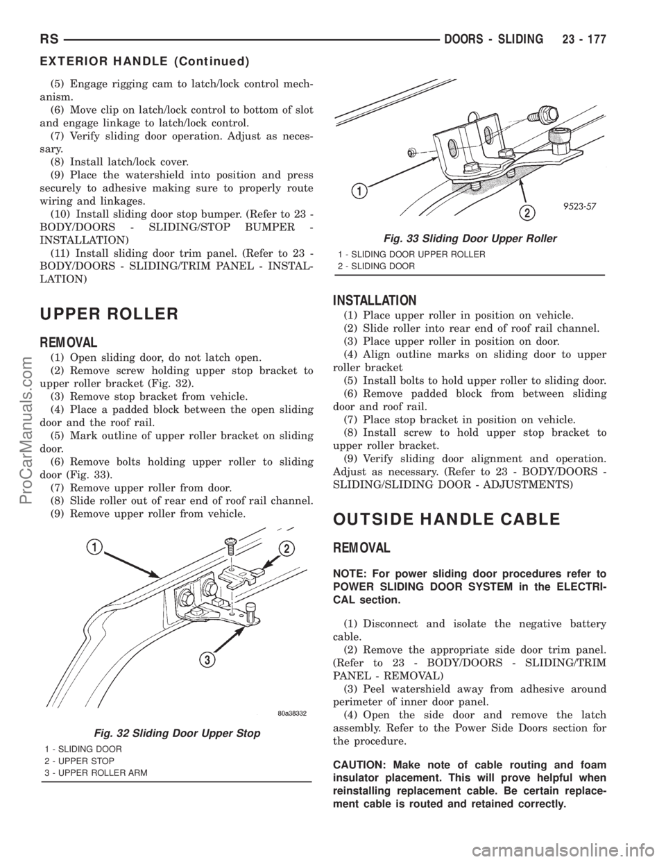
(1) Open sliding door, do not latch open.
(2) Remove screw holding upper stop bracket to
upper roller bracket (Fig. 32).
(3) Remove stop bracket from vehicle.
(4) Place a padded block between the open sliding
door and the roof rail.
(5) Mark outline of upper roller bracket on sliding
door.
(6) Remove bolts holding upper roller to sliding
door (Fig. 33).
(7) Remove upper roller from door.
(8) Slide roller out of rear end of roof rail channel.
(9) Remove upper roller from vehicle.
INSTALLATION
(1) Place upper roller in position on vehicle.
(2) Slide roller into rear end of roof rail channel.
(3) Place upper roller in position on door.
(4) Align outline marks on sliding door to upper
roller bracket
(5) Install bolts to hold upper roller to sliding door.
(6) Remove padded block from between sliding
door and roof rail.
(7) Place stop bracket in position on vehicle.
(8) Install screw to hold upper stop bracket to
upper roller bracket.
(9) Verify sliding door alignment and operation.
Adjust as necessary. (Refer to 23 - BODY/DOORS -
SLIDING/SLIDING DOOR - ADJUSTMENTS)
OUTSIDE HANDLE CABLE
REMOVAL
NOTE: For power sliding door procedures refer to
POWER SLIDING DOOR SYSTEM in the ELECTRI-
CAL section.
(1) Disconnect and isolate the negative battery
cable.
(2) Remove the appropriate side door trim panel.
(Refer to 23 - BODY/DOORS - SLIDING/TRIM
PANEL - REMOVAL)
(3) Peel watershield away from adhesive around
perimeter of inner door panel.
(4) Open the side door and remove the latch
assembly. Refer to the Power Side Doors section for
the procedure.
CAUTION: Make note of cable routing and foam
insulator placement. This will prove helpful when
reinstalling replacement cable. Be certain replace-
ment cable is routed and retained correctly.
Fig. 32 Sliding Door Upper Stop
1 - SLIDING DOOR
2 - UPPER STOP
3 - UPPER ROLLER ARM
Fig. 33 Sliding Door Upper Roller
1 - SLIDING DOOR UPPER ROLLER
2 - SLIDING DOOR
RSDOORS - SLIDING23 - 177
EXTERIOR HANDLE (Continued)
ProCarManuals.com
Page 2091 of 2321
(5) Trace the outside handle cable along its routing
path and disconnect from its retaining clips.
(6) Disconnect the outside handle cable from the
latch assembly. Gently pry cable sleeve retainer out
of the latch mounting braket and then unhook
swedged cable end from the latch link.
(7) Disconnect the outside handle cable from the
handle assembly. Gently pry cable sleeve retainer out
of the handle bracket and then unhook swedged
cable end from the handle link.
(8) Remove the outside handle cable from the side
door.
INSTALLATION
NOTE: For power sliding door procedures refer to
POWER SLIDING DOOR SYSTEM in the ELECTRI-
CAL section.
(1) Match the replacement cable up against the old
cable to verify the correct part.
(2) Position the outside handle cable on the side
door.
(3) Connect the outside handle cable on the handle
assembly. Hook the swedged cable end on the handle
link and gently push the cable sleeve retainer in the
handle bracket.
NOTE: The outside handle cable is marked with red
tape. It must be attached to the latch at the lowest
point. This is marked with a ªRº on the latch.
(4) Connect the outside handle cable on the latch
assembly. Hook the swedged cable end on the latch
link and gently push the cable sleeve retainer in the
latch bracket.
(5) Trace the outside handle cable along its routing
path and install on its retaining clips and position
foam insulators. Use previously made schematic as a
guide or remove the opposite side door trim panel
and use that door as a guide.
CAUTION: Be certain replacement cable is routed
and retained correctly and foam insulators are
properly positioned.
(6) Install the latch assembly. (Refer to 8 - ELEC-
TRICAL/POWER DOORS/LATCH - REMOVAL)
(7) Place the watershield into position and press
securely to adhesive making sure to properly route
wiring and linkages.
(8) Install the appropriate side door trim panel on
the vehicle. (Refer to 23 - BODY/DOORS - SLIDING/
TRIM PANEL - INSTALLATION)
(9) Connect the negative battery cable.
INSIDE HANDLE CABLE
REMOVAL
NOTE: For power sliding door procedures refer to
POWER SLIDING DOOR SYSTEM in the ELECTRI-
CAL section.
(1)
Disconnect and isolate the negative battery cable.
(2) Remove the appropriate side door trim panel
from the vehicle. (Refer to 23 - BODY/DOORS -
SLIDING/TRIM PANEL - REMOVAL)
(3) Peel watershield away from adhesive around
perimeter of inner door panel.
(4) Remove the inside handle assembly from the
side door. (Refer to 23 - BODY/DOORS - SLIDING/
INSIDE LATCH HANDLE - REMOVAL)
(5) Disconnect the inside handle cable from the
handle assembly. Gently pry cable sleeve retainer out
of the handle bracket and then unhook swedged
cable end from the handle link.
(6) Open the side door and remove the latch
assembly. Refer to the Power Side Doors section for
the procedure.
CAUTION: Make note of cable routing and foam
insulator placement. This will prove helpful when
reinstalling replacement cable. Be certain replace-
ment cable is routed and retained correctly.
(7) Trace the inside handle cable along its routing
path and disconnect from its retaining clips.
(8) Disconnect the inside handle cable from the
latch assembly. Gently pry cable sleeve retainer out
of the latch mounting bracket and then unhook
swedged cable end from the latch link.
(9) Remove the inside handle cable from the side
door.
INSTALLATION
NOTE: For power sliding door procedures refer to
POWER SLIDING DOOR SYSTEM in the ELECTRI-
CAL section.
(1) Match the replacement cable up against the old
cable to verify the correct part.
(2) Position the inside handle cable on the side
door.
(3) Connect the inside handle cable on the handle
assembly. Hook the swedged cable end on the handle
link and gently push the cable sleeve retainer in the
handle bracket.
(4) Install the inside handle assembly on the side
door. (Refer to 23 - BODY/DOORS - SLIDING/IN-
SIDE LATCH HANDLE - INSTALLATION)
23 - 178 DOORS - SLIDINGRS
OUTSIDE HANDLE CABLE (Continued)
ProCarManuals.com