2001 DODGE TOWN AND COUNTRY battery
[x] Cancel search: batteryPage 1440 of 2321
OPERATION
The signal represents throttle blade position. As
the position of the throttle blade changes, the resis-
tance of the TPS changes.
The PCM supplies approximately 5 volts to the
TPS. The TPS output voltage (input signal to the
powertrain control module) represents throttle blade
position. The TPS output voltage to the PCM varies
from approximately 0.6 volt at minimum throttle
opening (idle) to a maximum of 4.5 volts at wide open
throttle.
Along with inputs from other sensors, the PCM
uses the TPS input to determine current engine oper-
ating conditions. The PCM also adjusts fuel injectorpulse width and ignition timing based on these
inputs.
REMOVAL
(1) Disconnect the negative battery cable.
(2) Remove the electrical connector from the Inlet
Air Temperature sensor.
(3) Remove the air cleaner box lid. Remove hose
from throttle body.
(4) Disconnect the electrical connector at TPS.
(5) Disconnect the electrical connector at IAC.
(6) Remove the throttle and speed control cables
from throttle body.
(7) Remove 3 mounting bolts from throttle body.
(8) Remove throttle body.
(9) Disconnect the purge vacuum line from the
throttle body.
(10) Remove TPS from throttle body.
INSTALLATION
(1) Install TPS to throttle body.
(2) Disconnect the purge vacuum line from the
throttle body.
(3) Install throttle body.
(4) Install 3 mounting bolts from throttle body.
Tighten bolts.
(5) Install the throttle and speed control cables to
throttle body.
(6) Connect the electrical connector at TPS.
(7) Connect the electrical connector at IAC.
(8) Install the air cleaner box lid. Install hose to
throttle body.
(9) Install the electrical connector to the Inlet Air
Temperature sensor.
(10) Connect the negative battery cable.
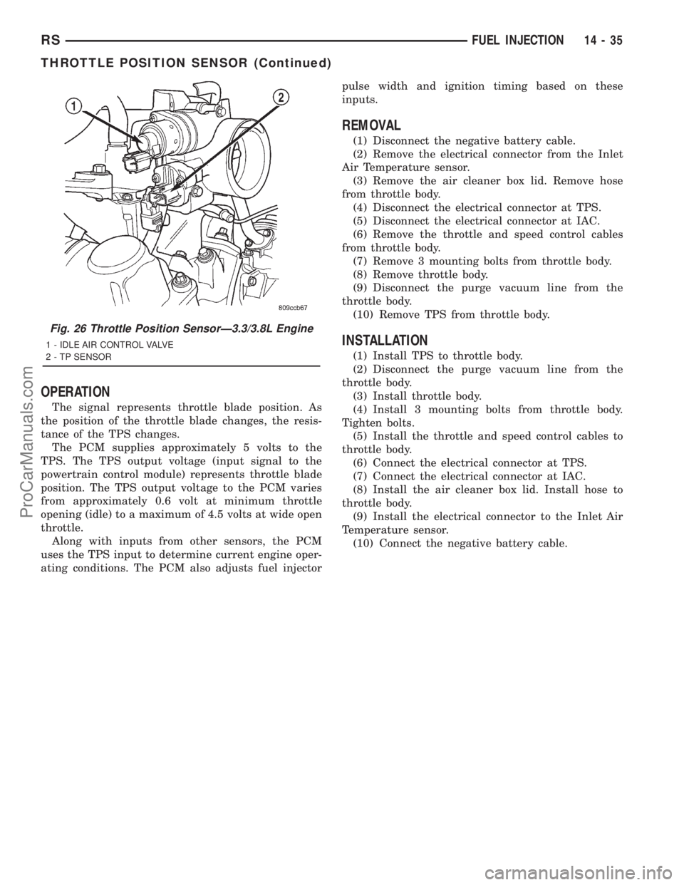
Fig. 26 Throttle Position SensorÐ3.3/3.8L Engine
1 - IDLE AIR CONTROL VALVE
2 - TP SENSOR
RSFUEL INJECTION14-35
THROTTLE POSITION SENSOR (Continued)
ProCarManuals.com
Page 1444 of 2321
FUEL DELIVERY
TABLE OF CONTENTS
page page
FUEL RAIL
DESCRIPTION............................3
OPERATION.............................3
REMOVAL...............................3
INSTALLATION............................4
FUEL FILTER / WATER SEPARATOR
DESCRIPTION............................4
OPERATION.............................4
FUEL LINES
DESCRIPTION............................5
OPERATION.............................5
DIAGNOSIS AND TESTING..................5HIGH-PRESSURE FUEL LINE LEAKS........5
FUEL TRANSFER PUMP
DESCRIPTION............................6
OPERATION.............................6
FUEL INJECTION PUMP
DESCRIPTION............................6
REMOVAL...............................6
INSTALLATION............................8
WATER IN FUEL SENSOR
DESCRIPTION............................9
OPERATION.............................9
FUEL RAIL
DESCRIPTION
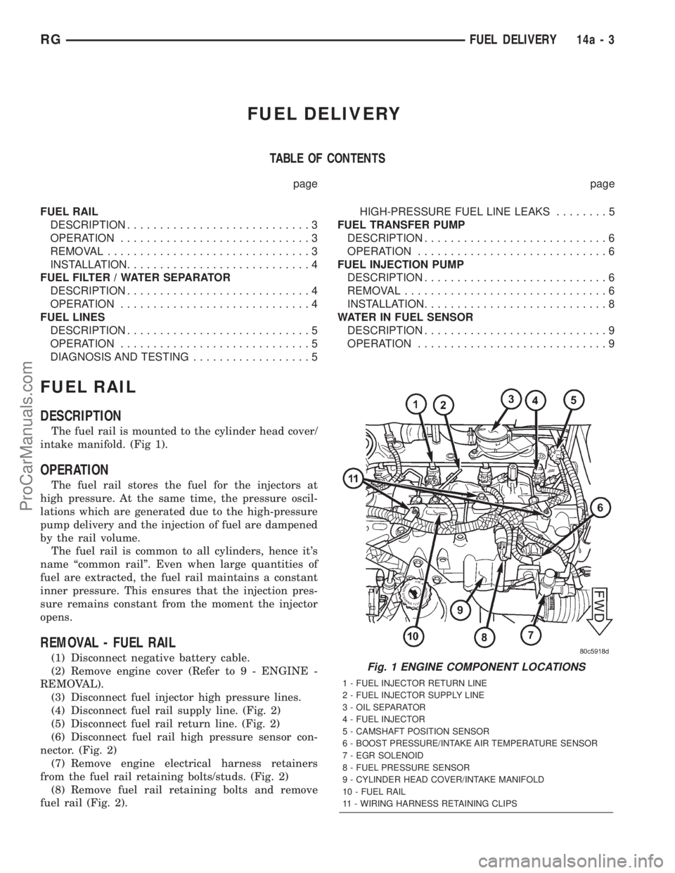
The fuel rail is mounted to the cylinder head cover/
intake manifold. (Fig 1).
OPERATION
The fuel rail stores the fuel for the injectors at
high pressure. At the same time, the pressure oscil-
lations which are generated due to the high-pressure
pump delivery and the injection of fuel are dampened
by the rail volume.
The fuel rail is common to all cylinders, hence it's
name ªcommon railº. Even when large quantities of
fuel are extracted, the fuel rail maintains a constant
inner pressure. This ensures that the injection pres-
sure remains constant from the moment the injector
opens.
REMOVAL - FUEL RAIL
(1) Disconnect negative battery cable.
(2) Remove engine cover (Refer to 9 - ENGINE -
REMOVAL).
(3) Disconnect fuel injector high pressure lines.
(4) Disconnect fuel rail supply line. (Fig. 2)
(5) Disconnect fuel rail return line. (Fig. 2)
(6) Disconnect fuel rail high pressure sensor con-
nector. (Fig. 2)
(7) Remove engine electrical harness retainers
from the fuel rail retaining bolts/studs. (Fig. 2)
(8) Remove fuel rail retaining bolts and remove
fuel rail (Fig. 2).Fig. 1 ENGINE COMPONENT LOCATIONS
1 - FUEL INJECTOR RETURN LINE
2 - FUEL INJECTOR SUPPLY LINE
3 - OIL SEPARATOR
4 - FUEL INJECTOR
5 - CAMSHAFT POSITION SENSOR
6 - BOOST PRESSURE/INTAKE AIR TEMPERATURE SENSOR
7 - EGR SOLENOID
8 - FUEL PRESSURE SENSOR
9 - CYLINDER HEAD COVER/INTAKE MANIFOLD
10 - FUEL RAIL
11 - WIRING HARNESS RETAINING CLIPS
RGFUEL DELIVERY14a-3
ProCarManuals.com
Page 1445 of 2321
INSTALLATION - FUEL RAIL
(1) Install fuel rail to intake manifold/cylinder
head cover (Fig. 2). Torque retaining bolts to
27.5N´m.
(2) Install engine electrical harness retainers from
the fuel rail retaining bolts/studs. (Fig. 2)
(3) Connect fuel rail high pressure sensor electri-
cal connector. (Fig. 2)
(4) Connect fuel rail return line. (Fig. 2)
(5) Connect fuel rail supply line. (Fig. 2)
(6) Connect fuel injector high pressure lines. (Fig.
2)
(7) Install engine cover (Refer to 9 - ENGINE -
INSTALLATION) .
(8) Connect negative battery cable.
FUEL FILTER / WATER
SEPARATOR
DESCRIPTION
The fuel filter/water separator assembly is located
under the vehicle in front of the rear axle assembly
(Fig. 3). The assembly also includes the fuel heater
and Water-In-Fuel (WIF) sensor.
OPERATION
The fuel filter/water separator protects the fuel
injection pump by removing water and contaminants
from the fuel. The construction of the filter/separator
allows fuel to pass through it, but helps prevent
moisture (water) from doing so. Moisture collects at
the bottom of the canister.
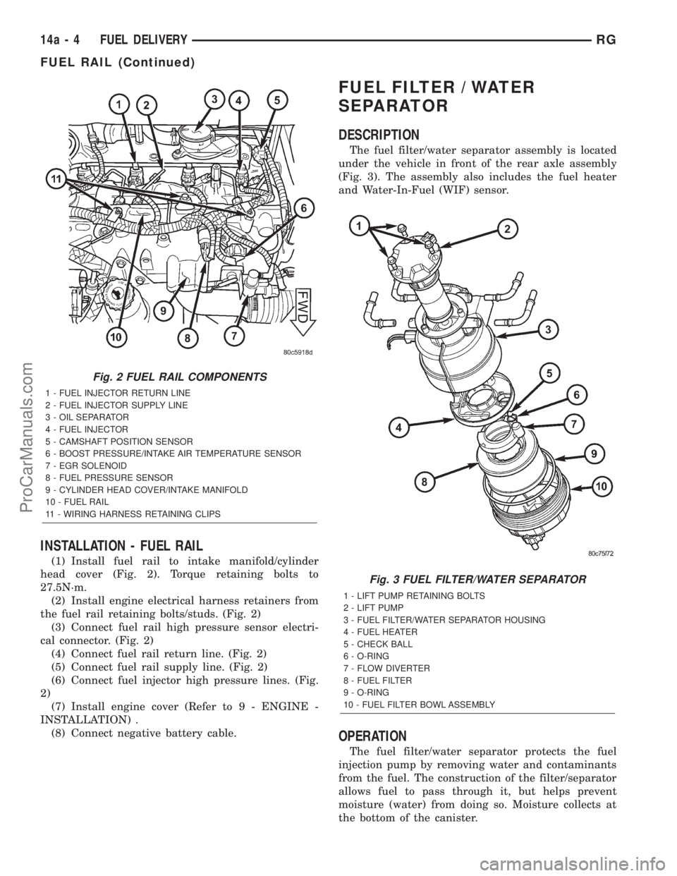
Fig. 2 FUEL RAIL COMPONENTS
1 - FUEL INJECTOR RETURN LINE
2 - FUEL INJECTOR SUPPLY LINE
3 - OIL SEPARATOR
4 - FUEL INJECTOR
5 - CAMSHAFT POSITION SENSOR
6 - BOOST PRESSURE/INTAKE AIR TEMPERATURE SENSOR
7 - EGR SOLENOID
8 - FUEL PRESSURE SENSOR
9 - CYLINDER HEAD COVER/INTAKE MANIFOLD
10 - FUEL RAIL
11 - WIRING HARNESS RETAINING CLIPS
Fig. 3 FUEL FILTER/WATER SEPARATOR
1 - LIFT PUMP RETAINING BOLTS
2 - LIFT PUMP
3 - FUEL FILTER/WATER SEPARATOR HOUSING
4 - FUEL HEATER
5 - CHECK BALL
6 - O-RING
7 - FLOW DIVERTER
8 - FUEL FILTER
9 - O-RING
10 - FUEL FILTER BOWL ASSEMBLY
14a - 4 FUEL DELIVERYRG
FUEL RAIL (Continued)
ProCarManuals.com
Page 1447 of 2321
FUEL TRANSFER PUMP
DESCRIPTION
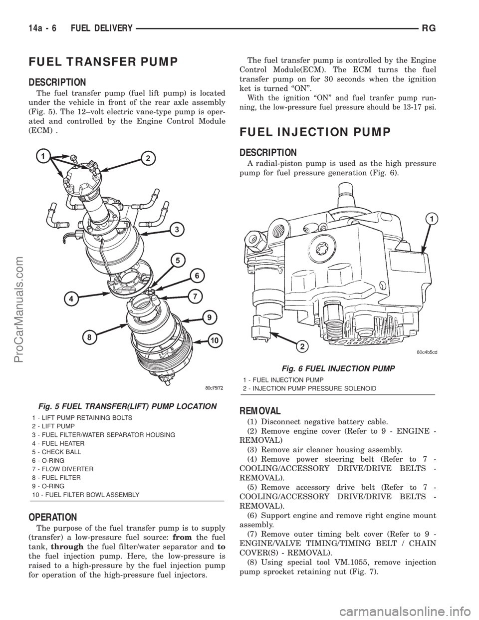
The fuel transfer pump (fuel lift pump) is located
under the vehicle in front of the rear axle assembly
(Fig. 5). The 12±volt electric vane-type pump is oper-
ated and controlled by the Engine Control Module
(ECM) .
OPERATION
The purpose of the fuel transfer pump is to supply
(transfer) a low-pressure fuel source:fromthe fuel
tank,throughthe fuel filter/water separator andto
the fuel injection pump. Here, the low-pressure is
raised to a high-pressure by the fuel injection pump
for operation of the high-pressure fuel injectors.The fuel transfer pump is controlled by the Engine
Control Module(ECM). The ECM turns the fuel
transfer pump on for 30 seconds when the ignition
ket is turned ªONº.
With the ignition ªONº and fuel tranfer pump run-
ning, the low-pressure fuel pressure should be 13-17 psi.
FUEL INJECTION PUMP
DESCRIPTION
A radial-piston pump is used as the high pressure
pump for fuel pressure generation (Fig. 6).
REMOVAL
(1) Disconnect negative battery cable.
(2) Remove engine cover (Refer to 9 - ENGINE -
REMOVAL)
(3) Remove air cleaner housing assembly.
(4) Remove power steering belt (Refer to 7 -
COOLING/ACCESSORY DRIVE/DRIVE BELTS -
REMOVAL).
(5) Remove accessory drive belt (Refer to 7 -
COOLING/ACCESSORY DRIVE/DRIVE BELTS -
REMOVAL).
(6) Support engine and remove right engine mount
assembly.
(7) Remove outer timing belt cover (Refer to 9 -
ENGINE/VALVE TIMING/TIMING BELT / CHAIN
COVER(S) - REMOVAL).
(8) Using special tool VM.1055, remove injection
pump sprocket retaining nut (Fig. 7).
Fig. 5 FUEL TRANSFER(LIFT) PUMP LOCATION
1 - LIFT PUMP RETAINING BOLTS
2 - LIFT PUMP
3 - FUEL FILTER/WATER SEPARATOR HOUSING
4 - FUEL HEATER
5 - CHECK BALL
6 - O-RING
7 - FLOW DIVERTER
8 - FUEL FILTER
9 - O-RING
10 - FUEL FILTER BOWL ASSEMBLY
Fig. 6 FUEL INJECTION PUMP
1 - FUEL INJECTION PUMP
2 - INJECTION PUMP PRESSURE SOLENOID
14a - 6 FUEL DELIVERYRG
ProCarManuals.com
Page 1450 of 2321
(12) Install accessory drive belt (Refer to 7 -
COOLING/ACCESSORY DRIVE/DRIVE BELTS -
INSTALLATION).
(13) Install power steering belt (Refer to 7 -
COOLING/ACCESSORY DRIVE/DRIVE BELTS -
INSTALLATION).
(14) Install air cleaner housing assembly.
(15) Install engine cover (Refer to 9 - ENGINE -
INSTALLATION).
(16) Connect negative battery cable.
WATER IN FUEL SENSOR
DESCRIPTION
The WIF sensor is located in the bowl assembly of
the fuel filter/water separator.
OPERATION
The sensor sends an input to the Engine Control
Module (ECM) when it senses water in the fuel filter/
water separator. As the water level in the filter/sep-
arator increases, the resistance across the WIF
sensor decreases. This decrease in resistance is sent
as a signal to the ECM and compared to a high
water standard value. Once the value reaches 30 to
40 kilohms, the ECM will activate the water-in-fuel
warning lamp through CCD bus circuits. This all
takes place when the ignition key is initially put in
the ON position. The ECM continues to monitor the
input at the end of the intake manifold air heater
post-heat cycle.
RGFUEL DELIVERY14a-9
FUEL INJECTION PUMP (Continued)
ProCarManuals.com
Page 1452 of 2321
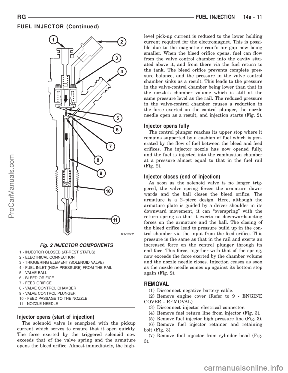
Injector opens (start of injection)
The solenoid valve is energized with the pickup
current which serves to ensure that it open quickly.
The force exerted by the triggered solenoid now
exceeds that of the valve spring and the armature
opens the bleed orifice. Almost immediately, the high-level pick-up current is reduced to the lower holding
current required for the electromagnet. This is possi-
ble due to the magnetic circuit's air gap now being
smaller. When the bleed orifice opens, fuel can flow
from the valve control chamber into the cavity situ-
ated above it, and from there via the fuel return to
the tank. The bleed orifice prevents complete pres-
sure balance, and the pressure in the valve control
chamber sinks as a result. This leads to the pressure
in the valve-control chamber being lower than that in
the nozzle's chamber volume which is still at the
same pressure level as the rail. The reduced pressure
in the valve-control chamber causes a reduction in
the force exerted on the control plunger, the nozzle
needle open as a result, and injection starts (Fig. 2).
Injector opens fully
The control plunger reaches its upper stop where it
remains supported by a cushion of fuel which is gen-
erated by the flow of fuel between the bleed and feed
orifices. The injector nozzle has now opened fully,
and the fuel is injected into the combustion chamber
at a pressure almost equal to that in the fuel rail
(Fig. 2).
Injector closes (end of injection)
As soon as the solenoid valve is no longer trig-
gered, the valve spring forces the armature down-
wards and the ball closes the bleed orifice. The
armature is a 2±piece design. Here, although the
armature plate is guided by a driver shoulder in its
downward movement, it can ªoverspringº with the
return spring so that it exerts no downwards-acting
forces on the armature and the ball. The closing of
the bleed orifice lead to pressure build up in the con-
trol chamber via the input from the feed orifice. This
pressure is the same as that in the rail and exerts an
increased force on the control plunger through its
end face. This force, together with that of the spring,
now exceeds the force exerted by the chamber volume
and the nozzle needle closes. Injection ceases as soon
as the nozzle needle comes up against its bottom stop
again (Fig. 2).
REMOVAL
(1) Disconnect negative battery cable.
(2) Remove engine cover (Refer to 9 - ENGINE
COVER - REMOVAL).
(3) Disconnect injector electrical connector.
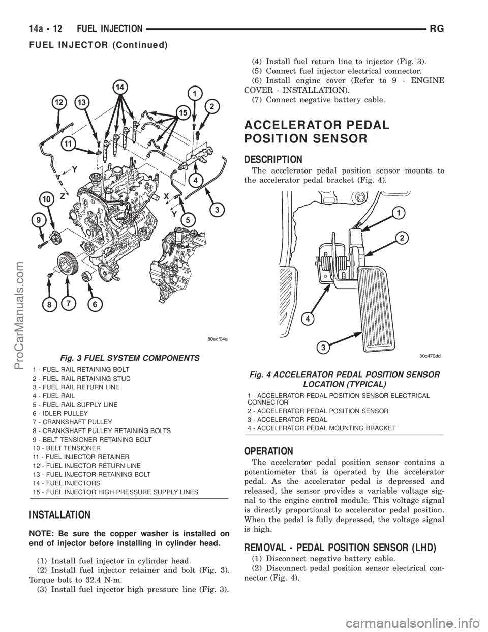
(4) Remove fuel return line from injector (Fig. 3).
(5) Remove fuel injector high pressure line (Fig. 3).
(6) Remove fuel injector retainer and retaining
bolt (Fig. 3).
(7) Remove fuel injector from cylinder head (Fig.
3).
Fig. 2 INJECTOR COMPONENTS
1 - INJECTOR CLOSED (AT-REST STATUS)
2 - ELECTRICAL CONNECTION
3 - TRIGGERING ELEMENT (SOLENOID VALVE)
4 - FUEL INLET (HIGH PRESSURE) FROM THE RAIL
5 - VALVE BALL
6 - BLEED ORIFICE
7 - FEED ORIFICE
8 - VALVE CONTROL CHAMBER
9 - VALVE CONTROL PLUNGER
10 - FEED PASSAGE TO THE NOZZLE
11 - NOZZLE NEEDLE
RGFUEL INJECTION14a-11
FUEL INJECTOR (Continued)
ProCarManuals.com
Page 1453 of 2321
INSTALLATION
NOTE: Be sure the copper washer is installed on
end of injector before installing in cylinder head.
(1) Install fuel injector in cylinder head.
(2) Install fuel injector retainer and bolt (Fig. 3).
Torque bolt to 32.4 N´m.
(3) Install fuel injector high pressure line (Fig. 3).(4) Install fuel return line to injector (Fig. 3).
(5) Connect fuel injector electrical connector.
(6) Install engine cover (Refer to 9 - ENGINE
COVER - INSTALLATION).
(7) Connect negative battery cable.
ACCELERATOR PEDAL
POSITION SENSOR
DESCRIPTION
The accelerator pedal position sensor mounts to
the accelerator pedal bracket (Fig. 4).
OPERATION
The accelerator pedal position sensor contains a
potentiometer that is operated by the accelerator
pedal. As the accelerator pedal is depressed and
released, the sensor provides a variable voltage sig-
nal to the engine control module. This voltage signal
is directly proportional to accelerator pedal position.
When the pedal is fully depressed, the voltage signal
is high.
REMOVAL - PEDAL POSITION SENSOR (LHD)
(1) Disconnect negative battery cable.
(2) Disconnect pedal position sensor electrical con-
nector (Fig. 4).
Fig. 3 FUEL SYSTEM COMPONENTS
1 - FUEL RAIL RETAINING BOLT
2 - FUEL RAIL RETAINING STUD
3 - FUEL RAIL RETURN LINE
4 - FUEL RAIL
5 - FUEL RAIL SUPPLY LINE
6 - IDLER PULLEY
7 - CRANKSHAFT PULLEY
8 - CRANKSHAFT PULLEY RETAINING BOLTS
9 - BELT TENSIONER RETAINING BOLT
10 - BELT TENSIONER
11 - FUEL INJECTOR RETAINER
12 - FUEL INJECTOR RETURN LINE
13 - FUEL INJECTOR RETAINING BOLT
14 - FUEL INJECTORS
15 - FUEL INJECTOR HIGH PRESSURE SUPPLY LINESFig. 4 ACCELERATOR PEDAL POSITION SENSOR
LOCATION (TYPICAL)
1 - ACCELERATOR PEDAL POSITION SENSOR ELECTRICAL
CONNECTOR
2 - ACCELERATOR PEDAL POSITION SENSOR
3 - ACCELERATOR PEDAL
4 - ACCELERATOR PEDAL MOUNTING BRACKET
14a - 12 FUEL INJECTIONRG
FUEL INJECTOR (Continued)
ProCarManuals.com
Page 1454 of 2321
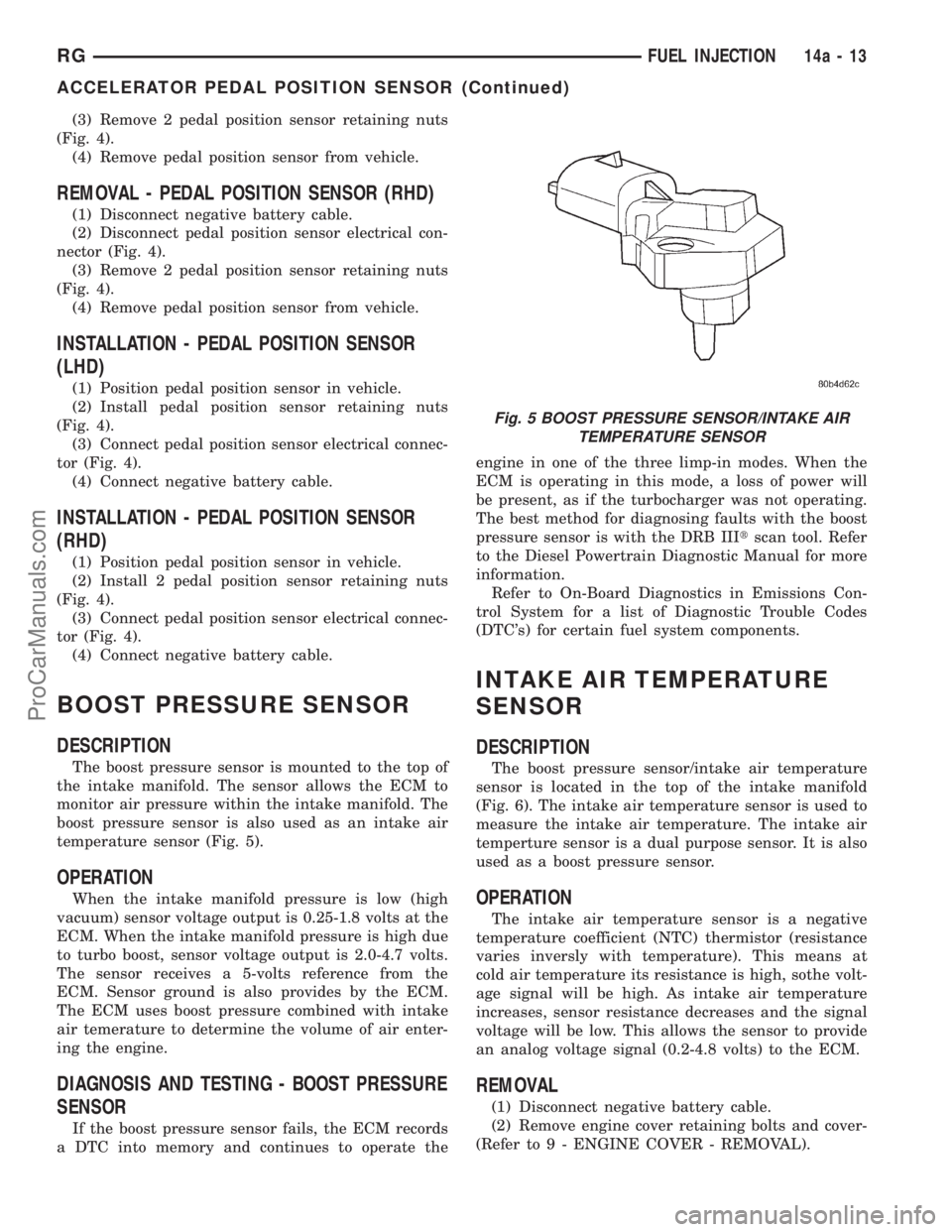
(3) Remove 2 pedal position sensor retaining nuts
(Fig. 4).
(4) Remove pedal position sensor from vehicle.
REMOVAL - PEDAL POSITION SENSOR (RHD)
(1) Disconnect negative battery cable.
(2) Disconnect pedal position sensor electrical con-
nector (Fig. 4).
(3) Remove 2 pedal position sensor retaining nuts
(Fig. 4).
(4) Remove pedal position sensor from vehicle.
INSTALLATION - PEDAL POSITION SENSOR
(LHD)
(1) Position pedal position sensor in vehicle.
(2) Install pedal position sensor retaining nuts
(Fig. 4).
(3) Connect pedal position sensor electrical connec-
tor (Fig. 4).
(4) Connect negative battery cable.
INSTALLATION - PEDAL POSITION SENSOR
(RHD)
(1) Position pedal position sensor in vehicle.
(2) Install 2 pedal position sensor retaining nuts
(Fig. 4).
(3) Connect pedal position sensor electrical connec-
tor (Fig. 4).
(4) Connect negative battery cable.
BOOST PRESSURE SENSOR
DESCRIPTION
The boost pressure sensor is mounted to the top of
the intake manifold. The sensor allows the ECM to
monitor air pressure within the intake manifold. The
boost pressure sensor is also used as an intake air
temperature sensor (Fig. 5).
OPERATION
When the intake manifold pressure is low (high
vacuum) sensor voltage output is 0.25-1.8 volts at the
ECM. When the intake manifold pressure is high due
to turbo boost, sensor voltage output is 2.0-4.7 volts.
The sensor receives a 5-volts reference from the
ECM. Sensor ground is also provides by the ECM.
The ECM uses boost pressure combined with intake
air temerature to determine the volume of air enter-
ing the engine.
DIAGNOSIS AND TESTING - BOOST PRESSURE
SENSOR
If the boost pressure sensor fails, the ECM records
a DTC into memory and continues to operate theengine in one of the three limp-in modes. When the
ECM is operating in this mode, a loss of power will
be present, as if the turbocharger was not operating.
The best method for diagnosing faults with the boost
pressure sensor is with the DRB IIItscan tool. Refer
to the Diesel Powertrain Diagnostic Manual for more
information.
Refer to On-Board Diagnostics in Emissions Con-
trol System for a list of Diagnostic Trouble Codes
(DTC's) for certain fuel system components.
INTAKE AIR TEMPERATURE
SENSOR
DESCRIPTION
The boost pressure sensor/intake air temperature
sensor is located in the top of the intake manifold
(Fig. 6). The intake air temperature sensor is used to
measure the intake air temperature. The intake air
temperture sensor is a dual purpose sensor. It is also
used as a boost pressure sensor.
OPERATION
The intake air temperature sensor is a negative
temperature coefficient (NTC) thermistor (resistance
varies inversly with temperature). This means at
cold air temperature its resistance is high, sothe volt-
age signal will be high. As intake air temperature
increases, sensor resistance decreases and the signal
voltage will be low. This allows the sensor to provide
an analog voltage signal (0.2-4.8 volts) to the ECM.
REMOVAL
(1) Disconnect negative battery cable.
(2) Remove engine cover retaining bolts and cover-
(Refer to 9 - ENGINE COVER - REMOVAL).
Fig. 5 BOOST PRESSURE SENSOR/INTAKE AIR
TEMPERATURE SENSOR
RGFUEL INJECTION14a-13
ACCELERATOR PEDAL POSITION SENSOR (Continued)
ProCarManuals.com