2001 DODGE TOWN AND COUNTRY ABS
[x] Cancel search: ABSPage 37 of 2321

Inspection and service should also be performed
anytime a malfunction is observed or suspected.
HOISTING
STANDARD PROCEDURE - HOISTING
Refer to Owner's Manual provided with vehicle for
proper emergency jacking procedures.
WARNING: THE HOISTING AND JACK LIFTING
POINTS PROVIDED ARE FOR A COMPLETE VEHI-
CLE. WHEN THE ENGINE OR REAR SUSPENSION
IS REMOVED FROM A VEHICLE, THE CENTER OF
GRAVITY IS ALTERED MAKING SOME HOISTING
CONDITIONS UNSTABLE. PROPERLY SUPPORT OR
SECURE VEHICLE TO HOISTING DEVICE WHEN
THESE CONDITIONS EXIST.
CAUTION: Do not position hoisting device on any
suspension component, including the front suspen-
sion crossmember, the rear leaf springs, and the
rear axle. Do not hoist on the front and rear
bumpers, the lower liftgate crossmember, the lower
radiator crossmember, the down standing flanges
on the sill or the front engine mount.
FOR PROPER HOIST PLACEMENT REFER
TO (Fig. 8).
The hoisting points are identified by S.A.E.
inverted triangle hoisting symbols (Fig. 8). The front
hoisting points are at the bottom of the font rail
below the hoisting symbol approximately 250mm
behind the front suspension crossmember. When
using outboard lift hoists, verify that the hoist lift
pads have been properly adjusted to eliminate con-
tact between the hoist arm and the down standing
flange on the sill. The rear hoisting points are the
leaf spring front mounting brackets. The hoist pad
must be positioned to pick up the flanges on the
bracket, not the leaf spring.
When servicing the leaf springs or the leaf spring
mounting brackets, special provisions are required to
support the rear of the vehicle. Position the rear
hoist pads under the horizontal surface on the bot-
tom of the sill, inboard adjacent to the flange and
centered fore/aft between the jacking indicator tabs
on the lower flange.DO NOT HOIST ON THE
FLANGE.Place a soft pad between the hoist and the
painted surface on the sill to avoid scratching the fin-
ish.
JUMP STARTING
TO JUMP START A DISABLED VEHICLE:
(1) Raise hood on disabled vehicle and visually
inspect engine compartment for:
²Battery cable clamp condition, clean if necessary.
²Frozen battery.
²Yellow or bright color test indicator, if equipped.
²Low battery fluid level.
²Generator drive belt condition and tension.
²Fuel fumes or leakage, correct if necessary.
CAUTION: If the cause of starting problem on dis-
abled vehicle is severe, damage to booster vehicle
charging system can result.
(2) When using another vehicle as a booster
source, park the booster vehicle within cable reach.
Turn off all accessories, set the parking brake, place
the automatic transmission in PARK or the manual
Fig. 8 HOISTING AND JACKING POINTS
1 - DRIVE ON LIFT
2 - FRAME CONTACT LIFT (SINGLE POST)
CHASSIS LIFT (NON-AXLE DUAL POST)
OUTBOARD LIFT (DUAL POST)
FLOOR JACK
3 - S.A.E. HOISTING SYMBOLS
0 - 16 LUBRICATION & MAINTENANCERS
MAINTENANCE SCHEDULES (Continued)
ProCarManuals.com
Page 38 of 2321
transmission in NEUTRAL and turn the ignition
OFF.
(3) On disabled vehicle, place gear selector in park
or neutral and set park brake. Turn off all accesso-
ries.
(4) Connect jumper cables to booster battery. RED
clamp to positive terminal (+). BLACK clamp to neg-
ative terminal (-). DO NOT allow clamps at opposite
end of cables to touch, electrical arc will result.
Review all warnings in this procedure.
(5) On disabled vehicle, connect RED jumper cable
clamp to positive (+) terminal. Connect BLACK
jumper cable clamp to engine ground as close to the
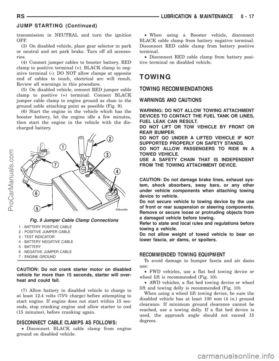
ground cable attaching point as possible (Fig. 9).
(6) Start the engine in the vehicle which has the
booster battery, let the engine idle a few minutes,
then start the engine in the vehicle with the dis-
charged battery.
CAUTION: Do not crank starter motor on disabled
vehicle for more than 15 seconds, starter will over-
heat and could fail.
(7) Allow battery in disabled vehicle to charge to
at least 12.4 volts (75% charge) before attempting to
start engine. If engine does not start within 15 sec-
onds, stop cranking engine and allow starter to cool
(15 minutes), before cranking again.
DISCONNECT CABLE CLAMPS AS FOLLOWS:
²Disconnect BLACK cable clamp from engine
ground on disabled vehicle.²When using a Booster vehicle, disconnect
BLACK cable clamp from battery negative terminal.
Disconnect RED cable clamp from battery positive
terminal.
²Disconnect RED cable clamp from battery posi-
tive terminal on disabled vehicle.
TOWING
TOWING RECOMMENDATIONS
WARNINGS AND CAUTIONS
WARNING: DO NOT ALLOW TOWING ATTACHMENT
DEVICES TO CONTACT THE FUEL TANK OR LINES,
FUEL LEAK CAN RESULT.
DO NOT LIFT OR TOW VEHICLE BY FRONT OR
REAR BUMPER.
DO NOT GO UNDER A LIFTED VEHICLE IF NOT
SUPPORTED PROPERLY ON SAFETY STANDS.
DO NOT ALLOW PASSENGERS TO RIDE IN A
TOWED VEHICLE.
USE A SAFETY CHAIN THAT IS INDEPENDENT
FROM THE TOWING ATTACHMENT DEVICE.
CAUTION: Do not damage brake lines, exhaust sys-
tem, shock absorbers, sway bars, or any other
under vehicle components when attaching towing
device to vehicle.
Do not secure vehicle to towing device by the use
of front or rear suspension or steering components.
Remove or secure loose or protruding objects from
a damaged vehicle before towing.
Refer to state and local rules and regulations before
towing a vehicle.
Do not allow weight of towed vehicle to bear on
lower fascia, air dams, or spoilers.
RECOMMENDED TOWING EQUIPMENT
To avoid damage to bumper fascia and air dams
use:
²FWD vehicles, use a flat bed towing device or
wheel lift is recommended (Fig. 10).
²AWD vehicles, a flat bed towing device or wheel
lift and towing dolly is recommended (Fig. 10).
When using a wheel lift towing device, be sure the
disabled vehicle has at least 100 mm (4 in.) ground
clearance. If minimum ground clearance cannot be
reached, use a towing dolly. If a flat bed device is
used, the approach angle should not exceed 15
degrees.
Fig. 9 Jumper Cable Clamp Connections
1 - BATTERY POSITIVE CABLE
2 - POSITIVE JUMPER CABLE
3 - TEST INDICATOR
4 - BATTERY NEGATIVE CABLE
5 - BATTERY
6 - NEGATIVE JUMPER CABLE
7 - ENGINE GROUND
RSLUBRICATION & MAINTENANCE0-17
JUMP STARTING (Continued)
ProCarManuals.com
Page 46 of 2321

²Inspect air filter element.
²Replace fuel filter/water separator element. (2)
²Check alignment.
140 000 km (86 000 Miles)
²Change engine oil. (1)
²Replace engine oil filter.
²Replace air filter element.
150 000 km (93 000 Miles)
²Change engine oil. (1)
²Replace engine oil filter.
²Inspect air filter element.
²Replace fuel filter/water separator element. (2)
²Check alignment.
160 000 km (100 000 Miles)
²Change engine oil. (1)
²Replace engine oil filter.
²Replace air filter element.
²Flush and replace engine coolant. (3)
²Change oil every 12 months regardless of mile-
age.
²The fuel filter/water separator element should
be replaced once a year if the vehicle is driven less
than 20 000 km annually or if power loss from fuel
starvation is detected.
²
Flush and replace engine coolant every 60 months
even if the vehicle is driven less than 160 000 km.
²Change manual transaxle fluid.
HOISTING
STANDARD PROCEDURE - HOISTING
Refer to Owner's Manual provided with vehicle for
proper emergency jacking procedures.
WARNING: THE HOISTING AND JACK LIFTING
POINTS PROVIDED ARE FOR A COMPLETE VEHI-
CLE. WHEN THE ENGINE OR REAR SUSPENSION
IS REMOVED FROM A VEHICLE, THE CENTER OF
GRAVITY IS ALTERED MAKING SOME HOISTING
CONDITIONS UNSTABLE. PROPERLY SUPPORT OR
SECURE VEHICLE TO HOISTING DEVICE WHEN
THESE CONDITIONS EXIST.
CAUTION: Do not position hoisting device on any
suspension component, including the front suspen-
sion crossmember, the rear leaf springs, and the
rear axle. Do not hoist on the front and rear
bumpers, the lower liftgate crossmember, the lower
radiator crossmember, the down standing flanges
on the sill or the front engine mount.
FOR PROPER HOIST PLACEMENT REFER
TO (Fig. 7).The hoisting points are identified by S.A.E.
inverted triangle hoisting symbols (Fig. 7). The front
hoisting points are at the bottom of the font rail
below the hoisting symbol approximately 250mm
behind the front suspension crossmember. When
using outboard lift hoists, verify that the hoist lift
pads have been properly adjusted to eliminate con-
tact between the hoist arm and the down standing
flange on the sill. The rear hoisting points are the
leaf spring front mounting brackets. The hoist pad
must be positioned to pick up the flanges on the
bracket, not the leaf spring.
When servicing the leaf springs or the leaf spring
mounting brackets, special provisions are required to
support the rear of the vehicle. Position the rear
hoist pads under the horizontal surface on the bot-
tom of the sill, inboard adjacent to the flange and
centered fore/aft between the jacking indicator tabs
on the lower flange.DO NOT HOIST ON THE
FLANGE.Place a soft pad between the hoist and the
painted surface on the sill to avoid scratching the fin-
ish.
Fig. 7 HOISTING AND JACKING POINTS
1 - Drive On Lift
2 - Frame Contact Lift (Single Post)
Chassis Lift (Non-Axle Dual Post)
Outboard Lift (Dual Post)
Floor Jack
3 - S.A.E. Hoisting Symbols
RGLUBRICATION & MAINTENANCE - RG - 2.5 L TURBO DIESEL0a-7
MAINTENANCE SCHEDULES (Continued)
ProCarManuals.com
Page 47 of 2321
JUMP STARTING
STANDARD PROCEDURE - JUMP STARTING
(1) Raise hood on disabled vehicle and visually
inspect engine compartment for:
²Battery cable clamp condition, clean if necessary.
²Frozen battery.
²Yellow or bright color test indicator, if equipped.
²Low battery fluid level.
²Generator drive belt condition and tension.
²Fuel fumes or leakage, correct if necessary.
CAUTION: If the cause of starting problem on dis-
abled vehicle is severe, damage to booster vehicle
charging system can result.
(2) When using another vehicle as a booster
source, park the booster vehicle within cable reach.
Turn off all accessories, set the parking brake, place
the automatic transmission in PARK or the manual
transmission in NEUTRAL and turn the ignition
OFF.
(3)
On disabled vehicle, place gear selector in park
or neutral and set park brake. Turn off all accessories.
(4) Connect jumper cables to booster battery. RED
clamp to positive terminal (+). BLACK clamp to neg-
ative terminal (-). DO NOT allow clamps at opposite
end of cables to touch, electrical arc will result.
Review all warnings in this procedure.
(5) On disabled vehicle, connect RED jumper cable
clamp to positive (+) terminal. Connect BLACK
jumper cable clamp to engine ground as close to the
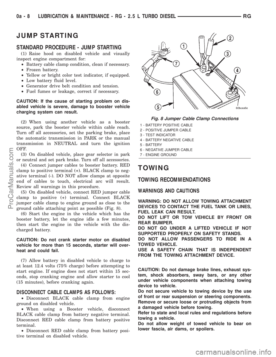
ground cable attaching point as possible (Fig. 8).
(6) Start the engine in the vehicle which has the
booster battery, let the engine idle a few minutes,
then start the engine in the vehicle with the dis-
charged battery.
CAUTION: Do not crank starter motor on disabled
vehicle for more than 15 seconds, starter will over-
heat and could fail.
(7) Allow battery in disabled vehicle to charge to
at least 12.4 volts (75% charge) before attempting to
start engine. If engine does not start within 15 sec-
onds, stop cranking engine and allow starter to cool
(15 minutes), before cranking again.
DISCONNECT CABLE CLAMPS AS FOLLOWS:
²Disconnect BLACK cable clamp from engine
ground on disabled vehicle.
²When using a Booster vehicle, disconnect
BLACK cable clamp from battery negative terminal.
Disconnect RED cable clamp from battery positive
terminal.
²Disconnect RED cable clamp from battery posi-
tive terminal on disabled vehicle.
TOWING
TOWING RECOMMENDATIONS
WARNINGS AND CAUTIONS
WARNING: DO NOT ALLOW TOWING ATTACHMENT
DEVICES TO CONTACT THE FUEL TANK OR LINES,
FUEL LEAK CAN RESULT.
DO NOT LIFT OR TOW VEHICLE BY FRONT OR
REAR BUMPER.
DO NOT GO UNDER A LIFTED VEHICLE IF NOT
SUPPORTED PROPERLY ON SAFETY STANDS.
DO NOT ALLOW PASSENGERS TO RIDE IN A
TOWED VEHICLE.
USE A SAFETY CHAIN THAT IS INDEPENDENT
FROM THE TOWING ATTACHMENT DEVICE.
CAUTION: Do not damage brake lines, exhaust sys-
tem, shock absorbers, sway bars, or any other
under vehicle components when attaching towing
device to vehicle.
Do not secure vehicle to towing device by the use
of front or rear suspension or steering components.
Remove or secure loose or protruding objects from
a damaged vehicle before towing.
Refer to state and local rules and regulations before
towing a vehicle.
Do not allow weight of towed vehicle to bear on
lower fascia, air dams, or spoilers.
Fig. 8 Jumper Cable Clamp Connections
1 - BATTERY POSITIVE CABLE
2 - POSITIVE JUMPER CABLE
3 - TEST INDICATOR
4 - BATTERY NEGATIVE CABLE
5 - BATTERY
6 - NEGATIVE JUMPER CABLE
7 - ENGINE GROUND
0a - 8 LUBRICATION & MAINTENANCE - RG - 2.5 L TURBO DIESELRG
ProCarManuals.com
Page 51 of 2321
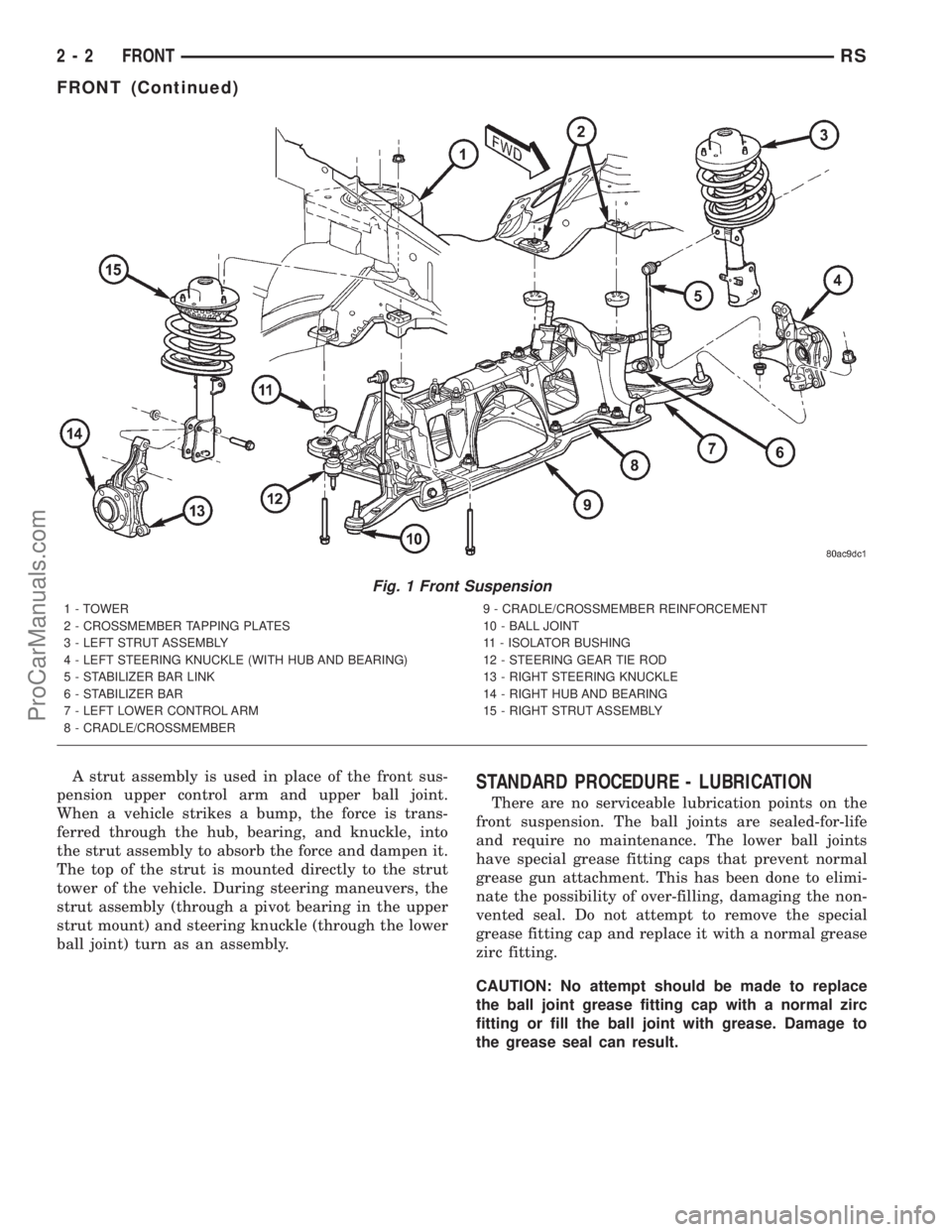
A strut assembly is used in place of the front sus-
pension upper control arm and upper ball joint.
When a vehicle strikes a bump, the force is trans-
ferred through the hub, bearing, and knuckle, into
the strut assembly to absorb the force and dampen it.
The top of the strut is mounted directly to the strut
tower of the vehicle. During steering maneuvers, the
strut assembly (through a pivot bearing in the upper
strut mount) and steering knuckle (through the lower
ball joint) turn as an assembly.STANDARD PROCEDURE - LUBRICATION
There are no serviceable lubrication points on the
front suspension. The ball joints are sealed-for-life
and require no maintenance. The lower ball joints
have special grease fitting caps that prevent normal
grease gun attachment. This has been done to elimi-
nate the possibility of over-filling, damaging the non-
vented seal. Do not attempt to remove the special
grease fitting cap and replace it with a normal grease
zirc fitting.
CAUTION: No attempt should be made to replace
the ball joint grease fitting cap with a normal zirc
fitting or fill the ball joint with grease. Damage to
the grease seal can result.
Fig. 1 Front Suspension
1 - TOWER
2 - CROSSMEMBER TAPPING PLATES
3 - LEFT STRUT ASSEMBLY
4 - LEFT STEERING KNUCKLE (WITH HUB AND BEARING)
5 - STABILIZER BAR LINK
6 - STABILIZER BAR
7 - LEFT LOWER CONTROL ARM
8 - CRADLE/CROSSMEMBER9 - CRADLE/CROSSMEMBER REINFORCEMENT
10 - BALL JOINT
11 - ISOLATOR BUSHING
12 - STEERING GEAR TIE ROD
13 - RIGHT STEERING KNUCKLE
14 - RIGHT HUB AND BEARING
15 - RIGHT STRUT ASSEMBLY
2 - 2 FRONTRS
FRONT (Continued)
ProCarManuals.com
Page 54 of 2321
DIAGNOSIS AND TESTING - HUB AND
BEARING (FRONT)
The condition of the front hub and bearing assem-
bly is diagnosed using the inspection and testing pro-
cedure detailed below.
The bearing contained in the Unit III front hub/
bearing assembly will produce noise and vibration
when worn or damaged. The noise will generally
change when the bearings are loaded. A road test of
the vehicle is normally required to determine the
location of a worn or damaged bearing.
Find a smooth level road surface and bring the
vehicle up to a constant speed. When vehicle is at a
constant speed, swerve the vehicle back and forth
from the left and to the right. This will load and
unload the bearings and change the noise level.
Where axle bearing damage is slight, the noise is
usually not noticeable at speeds above 48 km/h (30
mph).
REMOVAL - HUB AND BEARING
NOTE: Replacement of the Unit III front hub/bearing
assembly can be normally done without having to
remove the steering knuckle from the vehicle. In the
event that the hub/bearing is frozen in the steering
knuckle and cannot be removed by hand, it will
have to be pressed out of the steering knuckle. The
steering knuckle will require removal from the vehi-
cle to allow the hub/bearing assembly to be
pressed out of the steering knuckle. (Refer to 2 -
SUSPENSION/FRONT/KNUCKLE - REMOVAL)
(1) Raise vehicle on jack stands or centered on a
frame contact type hoist. See Hoisting in Lubrication
and Maintenance.
(2) Remove wheel lug nuts, and front tire and
wheel assembly.
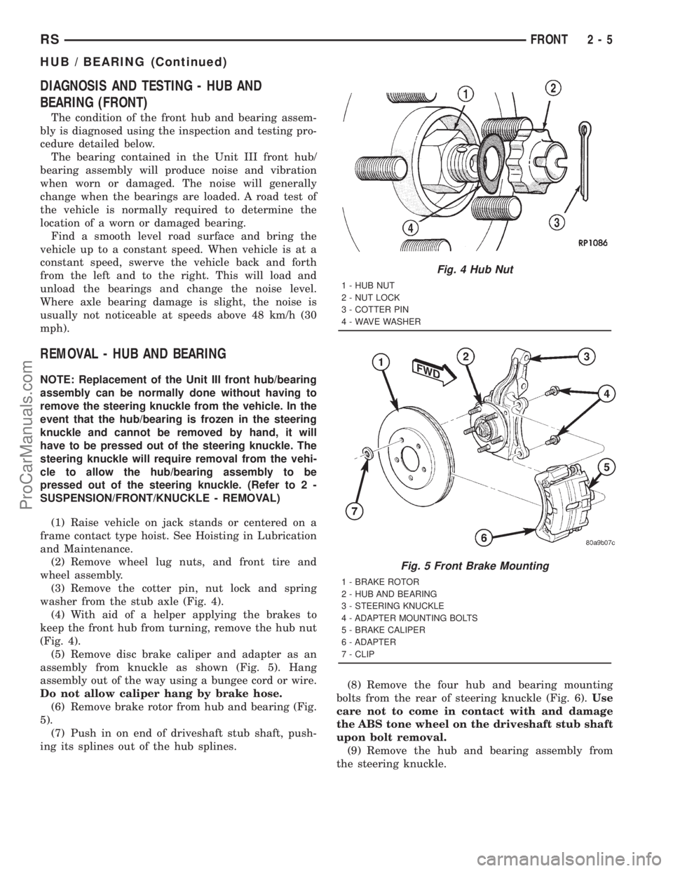
(3) Remove the cotter pin, nut lock and spring
washer from the stub axle (Fig. 4).
(4) With aid of a helper applying the brakes to
keep the front hub from turning, remove the hub nut
(Fig. 4).
(5) Remove disc brake caliper and adapter as an
assembly from knuckle as shown (Fig. 5). Hang
assembly out of the way using a bungee cord or wire.
Do not allow caliper hang by brake hose.
(6) Remove brake rotor from hub and bearing (Fig.
5).
(7) Push in on end of driveshaft stub shaft, push-
ing its splines out of the hub splines.(8) Remove the four hub and bearing mounting
bolts from the rear of steering knuckle (Fig. 6).Use
care not to come in contact with and damage
the ABS tone wheel on the driveshaft stub shaft
upon bolt removal.
(9) Remove the hub and bearing assembly from
the steering knuckle.
Fig. 4 Hub Nut
1 - HUB NUT
2 - NUT LOCK
3 - COTTER PIN
4 - WAVE WASHER
Fig. 5 Front Brake Mounting
1 - BRAKE ROTOR
2 - HUB AND BEARING
3 - STEERING KNUCKLE
4 - ADAPTER MOUNTING BOLTS
5 - BRAKE CALIPER
6 - ADAPTER
7 - CLIP
RSFRONT2-5
HUB / BEARING (Continued)
ProCarManuals.com
Page 75 of 2321
REAR
TABLE OF CONTENTS
page page
REAR
DESCRIPTION...........................26
OPERATION.............................26
SPECIFICATIONS........................27
SPECIAL TOOLS.........................28
BUSHINGS
REMOVAL..............................28
INSTALLATION...........................29
HUB / BEARING
DESCRIPTION...........................30
OPERATION.............................30
DIAGNOSIS AND TESTING.................30
HUB AND BEARING (REAR)...............30
REMOVAL..............................31
INSTALLATION...........................33
JOUNCE BUMPER
DESCRIPTION...........................35
OPERATION.............................35
REMOVAL..............................35
INSTALLATION...........................36
SHOCK ABSORBER
DESCRIPTION...........................36
OPERATION.............................36
REMOVAL..............................36
DISASSEMBLY...........................36
ASSEMBLY.............................37
INSTALLATION...........................38SPRING - AWD
DESCRIPTION...........................38
OPERATION.............................38
REMOVAL..............................38
INSTALLATION...........................39
SPRING - FWD
DESCRIPTION...........................40
OPERATION.............................40
REMOVAL..............................40
INSTALLATION...........................41
SPRING MOUNTS - FRONT
REMOVAL..............................42
INSTALLATION...........................42
SPRING MOUNTS - REAR
REMOVAL..............................43
INSTALLATION...........................43
STABILIZER BAR
DESCRIPTION...........................44
OPERATION.............................44
REMOVAL..............................44
INSTALLATION...........................44
TRACK BAR
DESCRIPTION...........................45
OPERATION.............................45
REMOVAL..............................45
INSTALLATION...........................45
REAR
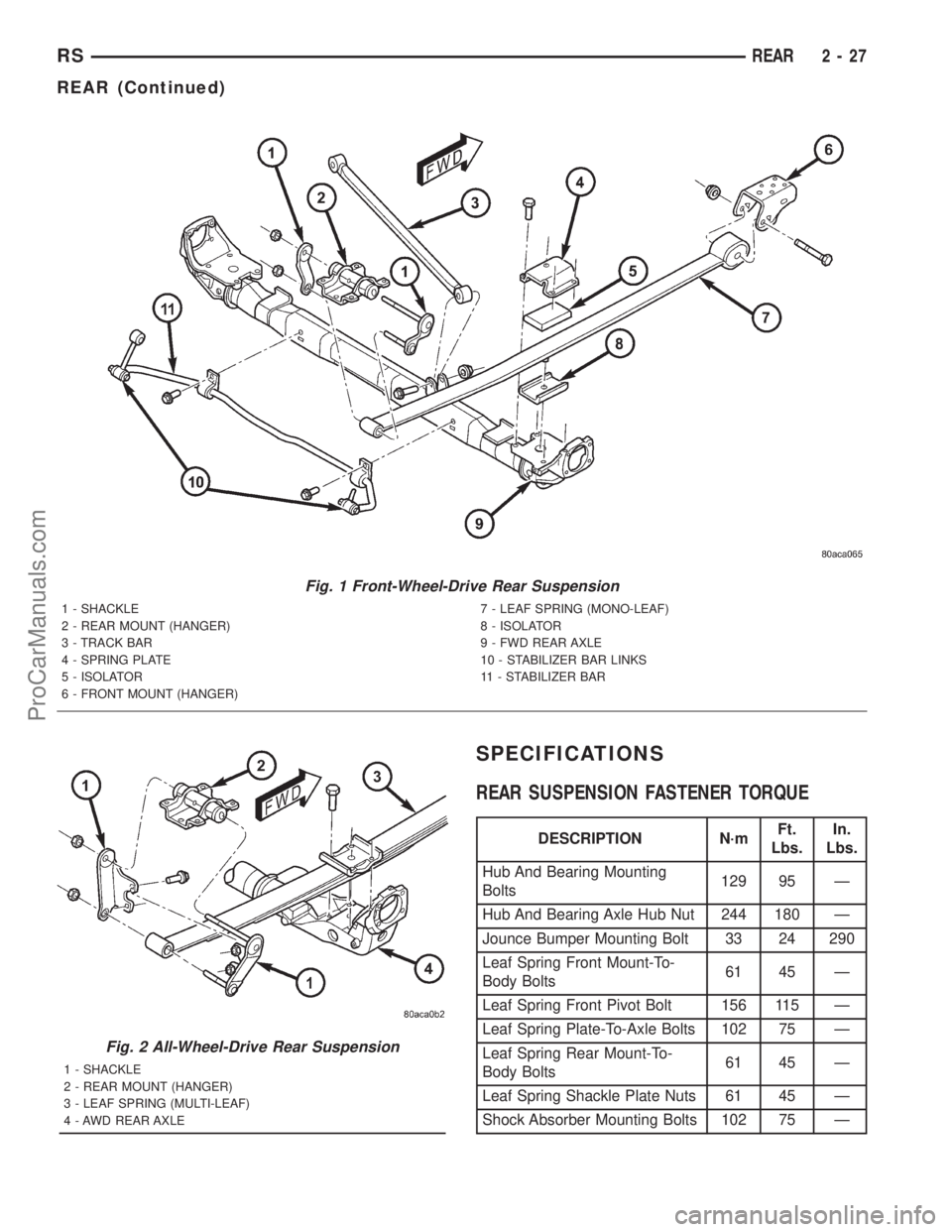
DESCRIPTION - REAR SUSPENSION
The rear suspension design on this vehicle uses
leaf springs, and a tube and casting axle (Fig. 1) (Fig.
2). The leaf springs used on the rear suspension of
this vehicle are of either a mono-leaf or multi-leaf
design.
There are 2 different rear suspension designs
available:
²Front-Wheel-Drive
²All-Wheel-Drive
The rear axle used on Front-Wheel-Drive applica-
tions of this vehicle is mounted to the rear leaf
springs using isolator bushings at the axle mounting
brackets.
The rear axle used on All-Wheel-Drive applications
of this vehicle is also mounted to the rear leafsprings, but does not use isolator bushings between
the rear axle and the leaf springs.
Each side of the rear suspension consists of these
major components:
²Leaf spring
²Jounce bumper
²Shock absorber
²Hub and bearing
²Track bar (one per suspension)
²Stabilizer bar (one per suspension)
OPERATION - REAR SUSPENSION
This rear suspension is designed to handle the var-
ious load requirements of the vehicle yet allow for a
comfortable ride.
The rear wheel bearings used are similar to the
bearings used in the front suspension. A hub and
bearing assembly is used.
2 - 26 REARRS
ProCarManuals.com
Page 76 of 2321
SPECIFICATIONS
REAR SUSPENSION FASTENER TORQUE
DESCRIPTION N´mFt.
Lbs.In.
Lbs.
Hub And Bearing Mounting
Bolts129 95 Ð
Hub And Bearing Axle Hub Nut 244 180 Ð
Jounce Bumper Mounting Bolt 33 24 290
Leaf Spring Front Mount-To-
Body Bolts61 45 Ð
Leaf Spring Front Pivot Bolt 156 115 Ð
Leaf Spring Plate-To-Axle Bolts 102 75 Ð
Leaf Spring Rear Mount-To-
Body Bolts61 45 Ð
Leaf Spring Shackle Plate Nuts 61 45 Ð
Shock Absorber Mounting Bolts 102 75 Ð
Fig. 1 Front-Wheel-Drive Rear Suspension
1 - SHACKLE
2 - REAR MOUNT (HANGER)
3 - TRACK BAR
4 - SPRING PLATE
5 - ISOLATOR
6 - FRONT MOUNT (HANGER)7 - LEAF SPRING (MONO-LEAF)
8 - ISOLATOR
9 - FWD REAR AXLE
10 - STABILIZER BAR LINKS
11 - STABILIZER BAR
Fig. 2 All-Wheel-Drive Rear Suspension
1 - SHACKLE
2 - REAR MOUNT (HANGER)
3 - LEAF SPRING (MULTI-LEAF)
4 - AWD REAR AXLE
RSREAR2-27
REAR (Continued)
ProCarManuals.com