2001 DODGE RAM check oil
[x] Cancel search: check oilPage 579 of 2889

swept to several calibration points on the gauge scale
in a prescribed sequence in order to confirm the func-
tionality of the gauge and the cluster control cir-
cuitry.
The PCM continually monitors the engine coolant
temperature sensor to determine the engine operat-
ing temperature. The PCM then sends the proper
engine coolant temperature messages to the instru-
ment cluster. For further diagnosis of the engine cool-
ant temperature gauge or the instrument cluster
circuitry that controls the gauge, (Refer to 8 - ELEC-
TRICAL/INSTRUMENT CLUSTER - DIAGNOSIS
AND TESTING). If the instrument cluster turns on
the check gauges indicator due to a high engine tem-
perature gauge reading, it may indicate that the
engine or the engine cooling system requires service.
For proper diagnosis of the engine coolant tempera-
ture sensor, the PCM, the CCD data bus, or the mes-
sage inputs to the instrument cluster that control the
engine coolant temperature gauge, a DRBIIItscan
tool is required. Refer to the appropriate diagnostic
information.
FUEL GAUGE
DESCRIPTION
A fuel gauge is standard equipment on all instru-
ment clusters. The fuel gauge is located in the lower
right quadrant of the instrument cluster, below the
oil pressure gauge. The fuel gauge consists of a mov-
able gauge needle or pointer controlled by the instru-
ment cluster circuitry and a fixed 90 degree scale on
the cluster overlay that reads left-to-right from E (or
Empty) to F (or Full). An International Control and
Display Symbol icon for ªFuelº is located on the clus-
ter overlay, directly below the highest graduation of
the gauge scale. The text ªFUEL DOORº and an
arrowhead pointed to the left side of the vehicle is
imprinted on the cluster overlay directly below the
fuel gauge to provide the driver with a reminder as
to the location of the fuel filler access. The fuel gauge
graphics are white against a black field except for a
single red graduation at the low end of the gauge
scale, making them clearly visible within the instru-
ment cluster in daylight. When illuminated from
behind by the panel lamps dimmer controlled cluster
illumination lighting with the exterior lamps turned
On, the white graphics appear blue-green and the
red graphics appear red. The orange gauge needle is
internally illuminated. Gauge illumination is pro-
vided by replaceable incandescent bulb and bulb
holder units located on the instrument cluster elec-
tronic circuit board. The fuel gauge is serviced as a
unit with the instrument cluster.
OPERATION
The fuel gauge gives an indication to the vehicle
operator of the level of fuel in the fuel tank. This
gauge is controlled by the instrument cluster circuit
board based upon the cluster programming and elec-
tronic messages received by the cluster from the
Powertrain Control Module (PCM) over the Chrysler
Collision Detection (CCD) data bus. The fuel gauge is
an air core magnetic unit that receives battery cur-
rent on the instrument cluster electronic circuit
board through the fused ignition switch output (st-
run) circuit whenever the ignition switch is in the On
or Start positions. The cluster is programmed to
move the gauge needle back to the low end of the
scale after the ignition switch is turned to the Off
position. The instrument cluster circuitry controls
the gauge needle position and provides the following
features:
²Percent Tank Full Message- Each time the
cluster receives a message from the PCM indicating
the percent tank full, the cluster programming
applies an algorithm to calculate the proper gauge
needle position, then moves the gauge needle to the
proper position on the gauge scale. The algorithm is
used to dampen gauge needle movement against the
negative effect that fuel sloshing within the fuel tank
can have on accurate inputs from the fuel tank send-
ing unit to the PCM.
²Less Than 12.5 Percent Tank Full Message-
Each time the cluster receives messages from the
PCM indicating the percent tank full is 12.5 (one-
eighth) or less for 10 consecutive seconds and the
vehicle speed is zero, or for 60 consecutive seconds
and the vehicle speed is greater than zero, the gauge
needle is moved to the proper position on the gauge
scale, the low fuel indicator is illuminated, and a sin-
gle chime tone is sounded. The low fuel indicator
remains illuminated until the cluster receives mes-
sages from the PCM indicating that the percent tank
full is greater than 12.5 (one-eighth) for 10 consecu-
tive seconds and the vehicle speed is zero, or for 60
consecutive seconds and the vehicle speed is greater
than zero, or until the ignition switch is turned to
the Off position, whichever occurs first. The chime
tone feature will only repeat during the same igni-
tion cycle if the low fuel indicator is cycled off and
then on again by the appropriate percent tank full
messages from the PCM.
²Less Than Empty Percent Tank Full Mes-
sage- Each time the cluster receives a message from
the PCM indicating the percent tank full is less than
empty, the gauge needle is moved to the far left (low)
end of the gauge scale and the low fuel indicator is
illuminated immediately. This message would indi-
cate that the fuel tank sender input to the PCM is a
short circuit.
8J - 20 INSTRUMENT CLUSTERBR/BE
ENGINE TEMPERATURE GAUGE (Continued)
Page 585 of 2889

orange gauge needle is internally illuminated. Gauge
illumination is provided by replaceable incandescent
bulb and bulb holder units located on the instrument
cluster electronic circuit board. The oil pressure
gauge is serviced as a unit with the instrument clus-
ter.
OPERATION
The oil pressure gauge gives an indication to the
vehicle operator of the engine oil pressure. This
gauge is controlled by the instrument cluster circuit
board based upon the cluster programming and elec-
tronic messages received by the cluster from the
Powertrain Control Module (PCM) over the Chrysler
Collision Detection (CCD) data bus. The oil pressure
gauge is an air core magnetic unit that receives bat-
tery current on the instrument cluster electronic cir-
cuit board through the fused ignition switch output
(st-run) circuit whenever the ignition switch is in the
On or Start positions. The cluster is programmed to
move the gauge needle back to the low end of the
scale after the ignition switch is turned to the Off
position. The instrument cluster circuitry controls
the gauge needle position and provides the following
features:
²Engine Oil Pressure Message- The instru-
ment cluster circuitry restricts the oil pressure gauge
needle operation in order to provide readings that
are consistent with customer expectations. Each time
the cluster receives a message from the PCM indicat-
ing the engine oil pressure is between about 6.9 kPa
(1 psi) and 137.9 kPa (20 psi) for gasoline engines, or
55 kPa (8 psi) and 58.6 kPa (8.5 psi) for diesel
engines, the cluster holds the gauge needle at a point
about 11 degrees above the low end of normal incre-
ment on the gauge scale. Each time the cluster
receives a message from the PCM indicating the
engine oil pressure is between about 517.1 kPa (75
psi) and 755 kPa (109.5 psi) for gasoline engines, or
551.6 kPa (80 psi) and 755 kPa (109.5 psi) for diesel
engines, the cluster holds the gauge needle at a point
about 7.4 degrees below the high end of normal
increment on the gauge scale. When the cluster
receives messages from the PCM indicating the
engine oil pressure is between about 137.9 kPa (20
psi) and 517.1 kPa (75 psi) for gasoline engines, or
58.6 kPa (8.5 psi) and 551.6 kPa (80 psi) for diesel
engines], the gauge needle is moved to the actual
pressure position on the gauge scale.
²Engine Oil Pressure Low Message- Each
time the cluster receives a message from the PCM
indicating the engine oil pressure is below about 6.9
kPa (1 psi) for gasoline engines, or 55 kPa (8 psi) for
diesel engines, the gauge needle is moved to the 0
kPa (0 psi) graduation at the far left (low) end of the
gauge scale, the check gauges indicator is illumi-nated, and a single chime tone is generated. The
gauge needle remains at the low end of the scale and
the check gauges indicator remains illuminated until
the cluster receives a message from the PCM indicat-
ing that the engine oil pressure is above about 6.9
kPa (1 psi) for gasoline engines, or 55 kPa (8 psi) for
diesel engines, or until the ignition switch is turned
to the Off position, whichever occurs first. The clus-
ter will only turn the check gauges indicator lamp on
in response to an engine oil pressure low message if
the engine speed message is greater than zero.
²Engine Oil Pressure High Message- Each
time the cluster receives a message from the PCM
indicating the engine oil pressure is above about 755
kPa (109.5 psi) for gasoline or diesel engines, the
gauge needle is moved to the 758.4 kPa (110 psi)
graduation at the far right (high) end of the gauge
scale. The gauge needle remains at the high end of
the scale until the cluster receives a message from
the PCM indicating that the engine oil pressure is
below about 755 kPa (109.5 psi) for gasoline or diesel
engines, or until the ignition switch is turned to the
Off position, whichever occurs first.
²Message Failure- If the cluster fails to receive
an engine oil pressure message, it will hold the
gauge needle at the last indication until a new mes-
sage is received, or until the ignition switch is turned
to the Off position, whichever occurs first.
²Actuator Test- Each time the cluster is put
through the actuator test, the gauge needle will be
swept to several calibration points on the gauge scale
in a prescribed sequence in order to confirm the func-
tionality of the gauge and the cluster control cir-
cuitry.
The PCM continually monitors the engine oil pres-
sure sensor to determine the engine oil pressure. The
PCM then sends the proper engine oil pressure mes-
sages to the instrument cluster. For further diagnosis
of the oil pressure gauge or the instrument cluster
circuitry that controls the gauge, (Refer to 8 - ELEC-
TRICAL/INSTRUMENT CLUSTER - DIAGNOSIS
AND TESTING). If the instrument cluster turns on
the check gauges indicator due to a low oil pressure
gauge reading, it may indicate that the engine or the
engine oiling system requires service. For proper
diagnosis of the engine oil pressure sensor, the PCM,
the CCD data bus, or the message inputs to the
instrument cluster that control the oil pressure
gauge, a DRBIIItscan tool is required. Refer to the
appropriate diagnostic information.
8J - 26 INSTRUMENT CLUSTERBR/BE
OIL PRESSURE GAUGE (Continued)
Page 591 of 2889

(st-run) circuit whenever the ignition switch is in the
On or Start positions; therefore, the LED will always
be off when the ignition switch is in any position
except On or Start. The LED bulb only illuminates
when it is provided a path to ground by the instru-
ment cluster transistor. The instrument cluster will
turn on the transmission over-temperature indicator
for the following reasons:
²Bulb Test- Each time the ignition switch is
turned to the On position the transmission over-tem-
perature indicator is illuminated for about two sec-
onds as a bulb test.
²Trans Over-Temp Lamp-On Message- Each
time the cluster receives a trans over-temp lamp-on
message from the PCM indicating that the transmis-
sion fluid temperature is 135É C (275É F) or higher,
the indicator will be illuminated and a single chime
tone is sounded. The lamp remains illuminated until
the cluster receives a trans over-temp lamp-off mes-
sage from the PCM, or until the ignition switch is
turned to the Off position, whichever occurs first.
The chime tone feature will only repeat during the
same ignition cycle if the transmission over-tempera-
ture indicator is cycled off and then on again by the
appropriate trans over-temp messages from the PCM.
²Actuator Test- Each time the cluster is put
through the actuator test, the indicator will be
turned on during the bulb check portion of the test to
confirm the functionality of the LED and the cluster
control circuitry.
The PCM continually monitors the transmission
temperature sensor to determine the transmission
operating condition, then sends the proper messages
to the instrument cluster. If the instrument cluster
turns on the transmission over-temperature indicator
due to a high transmission oil temperature condition,
it may indicate that the transmission and/or the
transmission cooling system are being overloaded or
that they require service. For further diagnosis of the
transmission over-temperature indicator or the
instrument cluster circuitry that controls the LED,
(Refer to 8 - ELECTRICAL/INSTRUMENT CLUS-
TER - DIAGNOSIS AND TESTING). For proper
diagnosis of the transmission temperature sensor, the
PCM, the CCD data bus, or the message inputs to
the instrument cluster that control the transmission
over-temperature indicator, a DRBIIItscan tool is
required. Refer to the appropriate diagnostic infor-
mation.
TURN SIGNAL INDICATORS
DESCRIPTION
Two turn signal indicators are standard equipment
on all instrument clusters. The turn signal indicatorsare located near the upper edge of the instrument
cluster overlay, between the speedometer and the
tachometer. Each turn signal indicator consists of a
stenciled cutout of the International Control and Dis-
play Symbol icon for ªTurn Warningº in the opaque
layer of the instrument cluster overlay. The dark
outer layer of the overlay prevents these icons from
being clearly visible when their lamps are not illumi-
nated. The icons appear in green through the trans-
lucent outer layer of the overlay when the indicator
is illuminated from behind by a replaceable incandes-
cent bulb and bulb holder unit located on the instru-
ment cluster electronic circuit board. The turn signal
indicators are serviced as a unit with the instrument
cluster.
OPERATION
The turn signal indicators give an indication to the
vehicle operator that the turn signal (left or right
indicator flashing) or hazard warning (both left and
right indicators flashing) have been selected. These
indicators are controlled by two individual hard
wired inputs to the instrument cluster electronic cir-
cuit board. The turn signal indicator bulbs are
grounded on the instrument cluster electronic circuit
board at all times. The turn signal indicator bulbs
only illuminate when they are provided with battery
current by the turn signal and hazard warning
switch circuitry of the left multi-function switch on
the steering column through separate left and right
turn signal inputs to the instrument cluster; there-
fore, these indicators can be illuminated, regardless
of the ignition switch position.
The turn signal indicators are connected in series
between ground and the output of the turn signal
and hazard warning switch circuitry, but in parallel
with the other turn signal circuits. This arrangement
allows the turn signal indicators to remain functional
regardless of the condition of the other circuits in the
turn signal and hazard warning system. For more
information on the turn signal and hazard warning
system, (Refer to 8 - ELECTRICAL/LAMPS/LIGHT-
ING - EXTERIOR - OPERATION - TURN SIGNAL &
HAZARD WARNING SYSTEM). The turn signal
indicators can be diagnosed using conventional diag-
nostic tools and methods.
DIAGNOSIS AND TESTING - TURN SIGNAL
INDICATORS
The diagnosis found here addresses an inoperative
turn signal indicator lamp condition. If the problem
being diagnosed is related to inoperative turn signals
or hazard warning lamps, be certain to repair the
turn signal and hazard warning system before
attempting to diagnose or repair the turn signal indi-
cators. If no turn signal or hazard warning system
8J - 32 INSTRUMENT CLUSTERBR/BE
TRANSMISSION OVERTEMP INDICATOR (Continued)
Page 608 of 2889
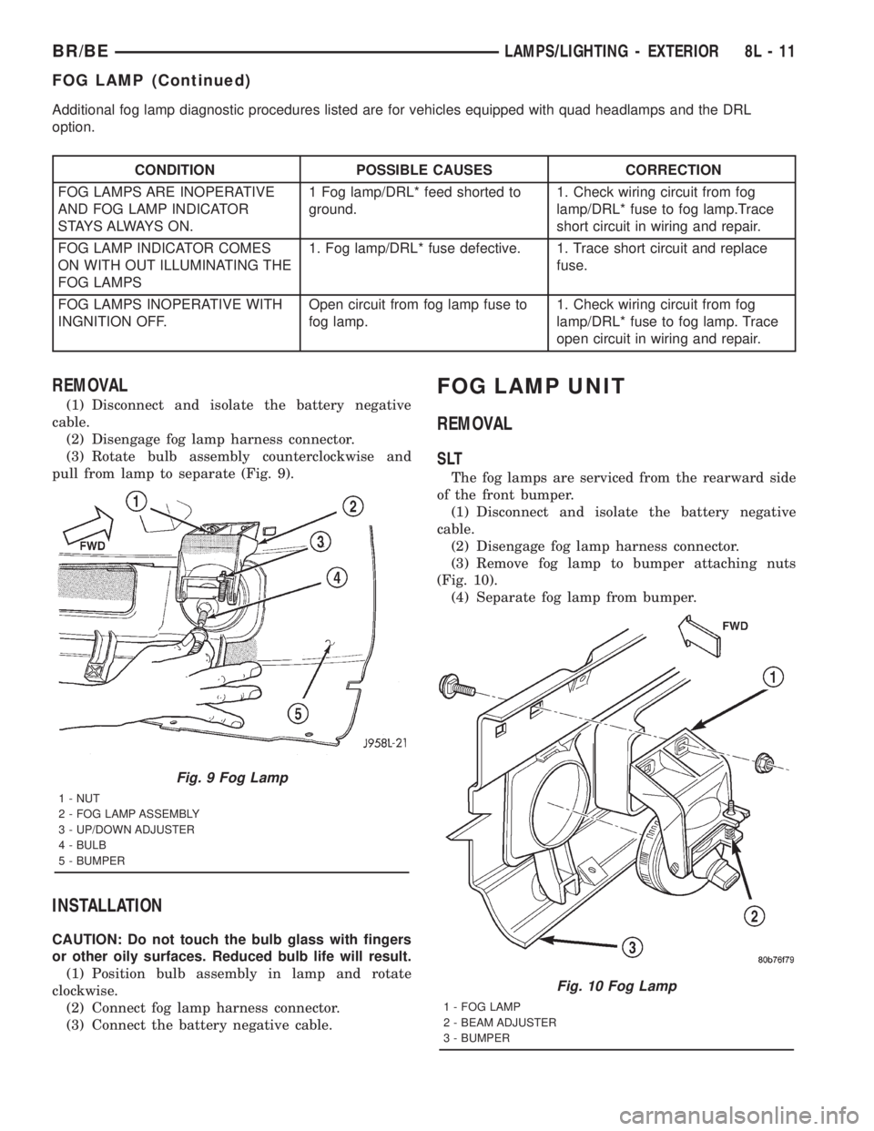
Additional fog lamp diagnostic procedures listed are for vehicles equipped with quad headlamps and the DRL
option.
CONDITION POSSIBLE CAUSES CORRECTION
FOG LAMPS ARE INOPERATIVE
AND FOG LAMP INDICATOR
S TAY S A LWAY S O N .1 Fog lamp/DRL* feed shorted to
ground.1. Check wiring circuit from fog
lamp/DRL* fuse to fog lamp.Trace
short circuit in wiring and repair.
FOG LAMP INDICATOR COMES
ON WITH OUT ILLUMINATING THE
FOG LAMPS1. Fog lamp/DRL* fuse defective. 1. Trace short circuit and replace
fuse.
FOG LAMPS INOPERATIVE WITH
INGNITION OFF.Open circuit from fog lamp fuse to
fog lamp.1. Check wiring circuit from fog
lamp/DRL* fuse to fog lamp. Trace
open circuit in wiring and repair.
REMOVAL
(1) Disconnect and isolate the battery negative
cable.
(2) Disengage fog lamp harness connector.
(3) Rotate bulb assembly counterclockwise and
pull from lamp to separate (Fig. 9).
INSTALLATION
CAUTION: Do not touch the bulb glass with fingers
or other oily surfaces. Reduced bulb life will result.
(1) Position bulb assembly in lamp and rotate
clockwise.
(2) Connect fog lamp harness connector.
(3) Connect the battery negative cable.
FOG LAMP UNIT
REMOVAL
SLT
The fog lamps are serviced from the rearward side
of the front bumper.
(1) Disconnect and isolate the battery negative
cable.
(2) Disengage fog lamp harness connector.
(3) Remove fog lamp to bumper attaching nuts
(Fig. 10).
(4) Separate fog lamp from bumper.
Fig. 9 Fog Lamp
1 - NUT
2 - FOG LAMP ASSEMBLY
3 - UP/DOWN ADJUSTER
4 - BULB
5 - BUMPER
Fig. 10 Fog Lamp
1 - FOG LAMP
2 - BEAM ADJUSTER
3 - BUMPER
BR/BELAMPS/LIGHTING - EXTERIOR 8L - 11
FOG LAMP (Continued)
Page 612 of 2889
CONDITION POSSIBLE CAUSES CORRECTION
6. Broken connector terminal or wire
splice in headlamp circuit.6. Repair connector terminal or wire splice.
HEADLAMPS (LOW
BEAM) DO NOT
ILLUMINATE.1. No ground for low beam circuit. 1. Ground should be present according to
Multifunction switch position. Check wiring
circuit from Multifunction switch to
headlamp . Trace open circuit in wiring and
repair.
Check Multifunction Switch for continuity.
HEADLAMPS (HIGH
BEAM) DO NOT
ILLUMINATE.1. No ground for high beam circuit. 1. Ground should be present according to
Multifunction switch position. Check wiring
circuit from Multifunction switch to
headlamp . Trace open circuit in wiring and
repair.
Check Multifunction Switch for continuity.
HEADLAMPS (LOW
BEAM) ALWAYS
ILLUMINATE AND CAN
NOT BE SHUT OFF.1. Low beam circuit from bulb to
Multifunction switch is shorted to
ground.1. Ground should be present according to
Multifunction switch position. Check wiring
circuit from Multifunction switch to
headlamp . Trace short circuit in wiring and
repair.
HEADLAMPS (HIGH
BEAM) ALWAYS
ILLUMINATE AND CAN
NOT BE SHUT OFF.1. High beam circuit from bulb to
Multifunction switch is shorted to
ground.1. Ground should be present according to
Multifunction switch position. Check wiring
circuit from Multifunction switch to
headlamp . Trace short circuit in wiring and
repair.
QUAD LAMPS DO NOT
ILLUMINATE AND HIGH
BEAMS ILLUMINATE.1. No voltage at either headlamp. 1. Voltage should always be present. Check
Quad lamp fuse. Check wiring circuit from
Quad lamp fuse to Quad lamp. Repeat for
left side
2. No ground for Quad beam circuit. 2. Ground should be present according to
Multifunction switch position. Check ground
at quad lamp relay. Check for battery
voltage at quad lamp relay. Check quad
lamp relay. Check relay control circuit (relay
coil to high beam).
3. If voltage and ground are present,
bulb(s) is defective.3.
Replace bulb(s).
HEADLAMP SWITCH OFF
HEADLAMPS AND
HIGHBEAM INDICATOR
REMAIN ON AND ARE
DIM.1. Headlamp switch feed circuit
shorted to ground.1. Check wiring circuit from right headlamp
fuse to headlamp. Repeat for left side.
Trace short circuit in wiring and repair.
HEADLAMP SWITCH ON
(LOW BEAMS ON), ONE
LOW BEAM ON AND
BOTH HIGH BEAMS DIM.1. Headlamp feed circuit shorted to
ground.1. Check wiring circuit from right headlamp
fuse to headlamp. Repeat for left side.
Trace short circuit in wiring and repair.
BR/BELAMPS/LIGHTING - EXTERIOR 8L - 15
HEADLAMP (Continued)
Page 613 of 2889
CONDITION POSSIBLE CAUSES CORRECTION
HEADLAMP SWITCH ON
(HIGH BEAMS ON), ONE
HIGH BEAM ON AND
BOTH LOW BEAMS DIM.1. Headlamp feed circuit shorted to
ground.1. Check wiring circuit from right headlamp
fuse to headlamp. Repeat for left side.
Trace short circuit in wiring and repair.
HEADLAMP SWITCH ON,
ONE HEADLAMP
FILAMENT WILL BE AT
FULL INTENSITY AND ALL
OTHER FILAMENTS ARE
ON AND DIM.1. Blown headlamp fuse. 1. Trace short circuit and replace fuse.
2. Open circuit from headlamp fuse
to headlamp.2. Repair open headlamp circuit.
1. HEADLAMPS STAY ON
WITH KEY OUT (DRLM
EQUIPPED VEHICLES).1. Failed DRLM 1. Replace DRLM.
*Canada vehicles must have lamps ON.
REMOVAL
On the driver side, the battery and battery tray
must be removed to service the headlamp bulb.
(1) Disconnect and isolate the battery negative
cable.
(2) Remove the battery tray (Refer to 8 - ELEC-
TRICAL/BATTERY SYSTEM/TRAY - REMOVAL).
(3) Disengage wire connector from headlamp
bulb(s).
(4) Remove retaining ring holding bulb(s) to head-
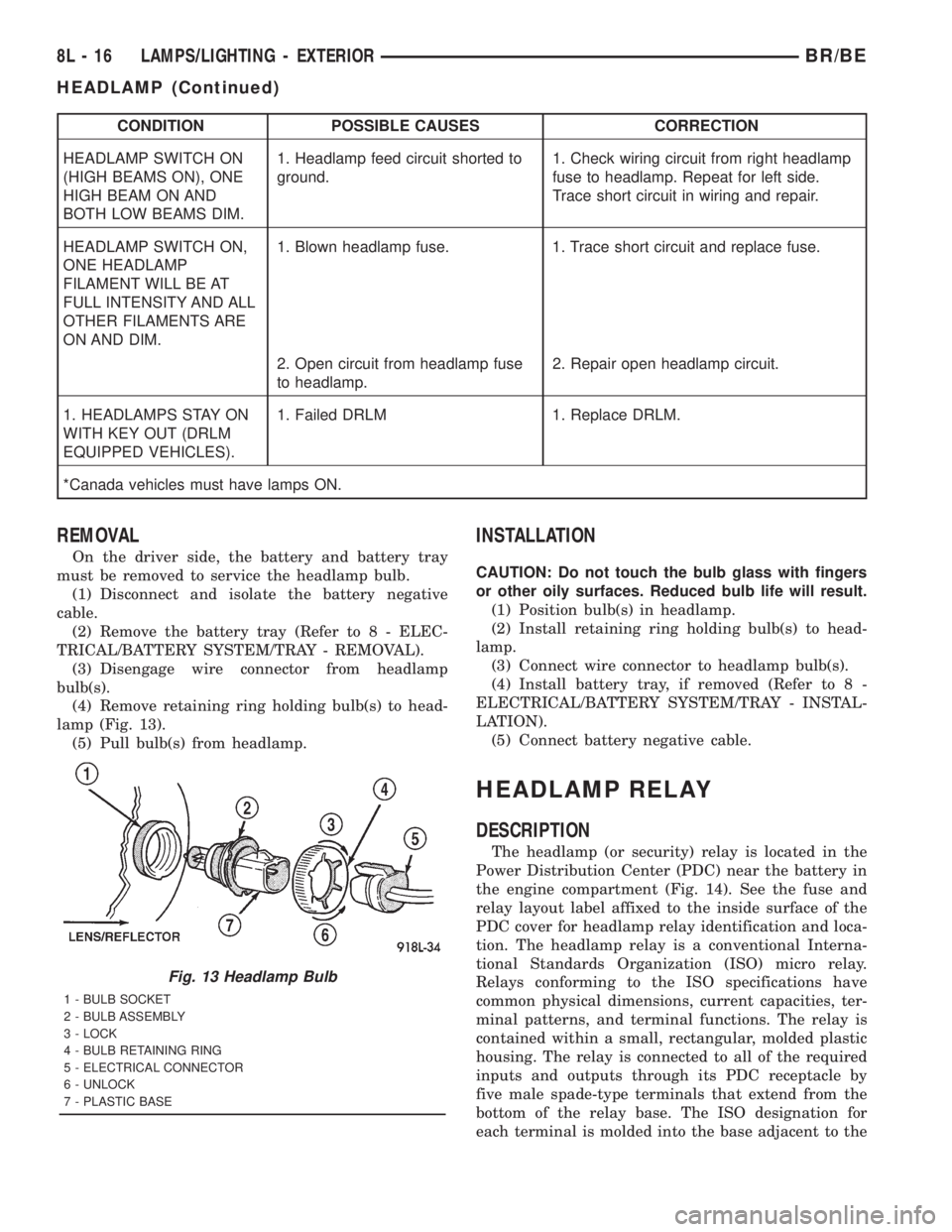
lamp (Fig. 13).
(5) Pull bulb(s) from headlamp.
INSTALLATION
CAUTION: Do not touch the bulb glass with fingers
or other oily surfaces. Reduced bulb life will result.
(1) Position bulb(s) in headlamp.
(2) Install retaining ring holding bulb(s) to head-
lamp.
(3) Connect wire connector to headlamp bulb(s).
(4) Install battery tray, if removed (Refer to 8 -
ELECTRICAL/BATTERY SYSTEM/TRAY - INSTAL-
LATION).
(5) Connect battery negative cable.
HEADLAMP RELAY
DESCRIPTION
The headlamp (or security) relay is located in the
Power Distribution Center (PDC) near the battery in
the engine compartment (Fig. 14). See the fuse and
relay layout label affixed to the inside surface of the
PDC cover for headlamp relay identification and loca-
tion. The headlamp relay is a conventional Interna-
tional Standards Organization (ISO) micro relay.
Relays conforming to the ISO specifications have
common physical dimensions, current capacities, ter-
minal patterns, and terminal functions. The relay is
contained within a small, rectangular, molded plastic
housing. The relay is connected to all of the required
inputs and outputs through its PDC receptacle by
five male spade-type terminals that extend from the
bottom of the relay base. The ISO designation for
each terminal is molded into the base adjacent to the
Fig. 13 Headlamp Bulb
1 - BULB SOCKET
2 - BULB ASSEMBLY
3 - LOCK
4 - BULB RETAINING RING
5 - ELECTRICAL CONNECTOR
6 - UNLOCK
7 - PLASTIC BASE
8L - 16 LAMPS/LIGHTING - EXTERIORBR/BE
HEADLAMP (Continued)
Page 630 of 2889
LAMPS/LIGHTING - INTERIOR
TABLE OF CONTENTS
page page
LAMPS/LIGHTING - INTERIOR
SPECIFICATIONS........................33
DOME LAMP
REMOVAL..............................33
INSTALLATION...........................33
DOOR AJAR SWITCH
DESCRIPTION...........................34
DIAGNOSIS AND TESTING.................34
DOOR AJAR SWITCH....................34
REMOVAL..............................35
INSTALLATION...........................35GLOVE BOX LAMP AND SWITCH
REMOVAL..............................35
INSTALLATION...........................35
READING LAMP
DESCRIPTION...........................36
OPERATION.............................36
REMOVAL..............................36
INSTALLATION...........................36
VANITY LAMP
REMOVAL..............................37
INSTALLATION...........................37
LAMPS/LIGHTING - INTERIOR
SPECIFICATIONS
INTERIOR LAMPS
LAMP BULB
A/C HEATER CONTROL 158
ASH RECEIVER 161
CIGAR LIGHTER 161
HEADLAMP SWITCH 158
HEATER CONTROL 158
INSTRUMENT CLUSTER PC194
RADIO ASC
AIRBAG HIGH LINE PC194
AIRBAG LOW LINE PC74
ANTI-LOCK BRAKE PC74
BATTERY VOLTAGE PC194
BRAKE WARNING PC194
CHECK ENGINE PC74
ENGINE OIL PRESSURE PC74
FOUR WHEEL DRIVE PC194
HIGH BEAM PC194
LOW FUEL PC194
LOW WASHER FLUID PC74
MAINTENANCE
REQUIREDPC74
MESSAGE CENTER PC194
SEAT BELT PC74
LAMP BULB
TURN SIGNAL PC194
UPSHIFT PC74
DOME 1004
GLOVE COMPARTMENT 1891
VANITY MIRROR LAMP P/N 6501966
DOME LAMP
REMOVAL
(1) Using a small flat blade, pry the left side (driv-
er's side) of the dome lamp lens downward from
dome lamp.
(2) Allow the lens to hang down (Fig. 1) , this will
disengage the right side of the lamp (passenger's
side) from the headliner.
(3) Pull the right side of the lamp down and slide
the lamp to the right (Fig. 2) .
(4) Separate the lamp from the headliner.
(5) Disengage dome lamp wire connector from body
wire harness.
(6) Separate dome lamp from vehicle.
INSTALLATION
(1) Position dome lamp at headliner.
(2) Connect dome lamp wire connector to body
wire harness.
(3) Position the left side of the lamp in the head-
liner opening and slide lamp to the left.
(4) Push the right side of the lamp in the head-
liner opening and push the lamp lens up into the
lamp to secure.
BR/BELAMPS/LIGHTING - INTERIOR 8L - 33
Page 653 of 2889
²Horn Chirp- If this feature is enabled, the
CTM provides a horn chirp by internally pulling the
control coil of the horn relay to ground through a
hard wired circuit output.
²Illuminated Entry- The CTM provides illumi-
nated entry by internally controlling the current flow
to the courtesy lamps in the vehicle through a hard
wired output circuit.
²Panic Mode- The CTM provides the horn pulse
and headlight flash by internally pulling the control
coils of the horn relay and headlamp relay to ground
through hard wired circuit outputs. The CTM con-
trols the current flow to the courtesy lamps in the
vehicle through a hard wired output circuit. The
CTM also monitors the vehicle speed through elec-
tronic messages it receives from the Powertrain Con-
trol Module (PCM) over the Chrysler Collision
Detection (CCD) data bus network.
The RKE system operates on battery current received
through a fused B(+) circuit from a fuse in the Junction
Block (JB) so that the system remains functional,
regardless of the ignition switch position. The RKE sys-
tem can retain the vehicle access codes of up to four
RKE transmitters. The transmitter codes are retained
in RKE system memory, even if the battery is discon-
nected. If a transmitter is faulty or is lost, new trans-
mitter vehicle access codes can be programmed into the
system using a DRBIIItscan tool. Refer to the appro-
priate diagnostic information. Many of the electronic
features in the vehicle controlled or supported by the
high-line or premium versions of the CTM are program-
mable using the DRBIIItscan tool. In addition, the
high-line/premium CTM software is Flash compatible,
which means it can be reprogrammed using Flash
reprogramming procedures. However, if any of the CTM
hardware components are damaged or faulty, the entire
CTM unit must be replaced. The hard wired inputs or
outputs of the CTM can be diagnosed using conven-
tional diagnostic tools and methods; however, for diag-
nosis of the high-line or premium versions of the CTM
or the CCD data bus, the use of a DRBIIItscan tool is
required. Refer to the appropriate diagnostic informa-
tion.
DIAGNOSIS AND TESTING - POWER LOCK
SYSTEM
The following tests provide a preliminary diagnosis
for the power lock system usedonlyon vehicles
equipped with a base version of the Central Timer
Module (CTM). These testsdo notapply to the diag-
nosis of the power lock system used on vehicles
equipped with the optional Remote Keyless Entry
(RKE) system, which includes a high-line or premium
CTM. (Refer to 8 - ELECTRICAL/POWER LOCKS -
DIAGNOSIS AND TESTING - POWER LOCK &
REMOTE KEYLESS ENTRY SYSTEM). Refer to theappropriate wiring information. The wiring informa-
tion includes wiring diagrams, proper wire and con-
nector repair procedures, details of wire harness
routing and retention, connector pin-out information
and location views for the various wire harness con-
nectors, splices and grounds.
PRELIMINARY TESTS
To begin this test, note the system operation while
you actuate both the Lock and Unlock functions with
the power lock switches. Then, proceed as follows:
²If the entire power lock system fails to function
with both of the power lock switches, check the fused
B(+) fuse in the Junction Block (JB). If the fuse is
OK, check the ground circuit between the driver side
power lock switch and ground (G301). If the ground
circuit is OK, proceed to the diagnosis of the power
lock motors. (Refer to 8 - ELECTRICAL/POWER
LOCKS/POWER LOCK MOTOR - DIAGNOSIS AND
TESTING).
²If the entire power lock system fails to function
with only one of the power lock switches, proceed to
diagnosis of the power lock switches. (Refer to 8 -
ELECTRICAL/POWER LOCKS/POWER LOCK
SWITCH - DIAGNOSIS AND TESTING).
²If only one power lock motor fails to operate
with both power lock switches, proceed to diagnosis
of the power lock motor. (Refer to 8 - ELECTRICAL/
POWER LOCKS/POWER LOCK MOTOR - DIAGNO-
SIS AND TESTING).
DIAGNOSIS AND TESTING - POWER LOCK &
REMOTE KEYLESS ENTRY SYSTEM
The following tests include a preliminary diagnosis
for the power lock system usedonlyon vehicles
equipped with the optional Remote Keyless Entry
(RKE) system, which includes a high-line or premium
Central Timer Module (CTM). These testsdo not
apply to the diagnosis of the power lock system on
vehicles equipped with a base version of the CTM.
(Refer to 8 - ELECTRICAL/POWER LOCKS - DIAG-
NOSIS AND TESTING - POWER LOCK SYSTEM).
These tests will help to diagnose the hard wired
components and circuits of the power lock system.
However, these tests may not prove conclusive in the
diagnosis of this system. In order to obtain conclusive
testing of the power lock and RKE system, the
Chrysler Collision Detection (CCD) data bus network
and all of the electronic modules that provide inputs
to, or receive outputs from the power lock and RKE
system components must be checked.
The most reliable, efficient, and accurate means to
diagnose the power lock and RKE system requires the
use of a DRBIIItscan tool. The DRBIIItscan tool can
provide confirmation that the CCD data bus is func-
tional, that all of the electronic modules are sending
8N - 4 POWER LOCKSBR/BE
POWER LOCKS (Continued)