2001 DODGE RAM check oil
[x] Cancel search: check oilPage 549 of 2889

removed). Then continue to slowly rotate engine
clockwise until indicating mark (Fig. 18) is aligned to
0 degree (TDC) mark on timing chain cover.
(1) Clean top of cylinder block for a good seal
between distributor base and block.
(2) Lightly oil the rubber o-ring seal on the distrib-
utor housing.
(3) Install rotor to distributor shaft.
(4) Position distributor into engine to its original
position. Engage tongue of distributor shaft with slot
in distributor oil pump drive gear. Position rotor to
the number one spark plug cable position.
(5) Install distributor holddown clamp and clamp
bolt. Do not tighten bolt at this time.(6) Rotate the distributor housing until rotor is
aligned to CYL. NO. 1 alignment mark on the cam-
shaft position sensor (Fig. 19) .
(7) Tighten clamp holddown bolt (Fig. 20) to 22.5
N´m (200 in. lbs.) torque.
(8) Connect camshaft position sensor wiring har-
ness to main engine harness.
(9) Install distributor cap. Tighten mounting
screws.
(10) Refer to the following, Checking Distributor
Position.
Checking Distributor Position
To verify correct distributor rotational position, the
DRB scan tool must be used.
WARNING: WHEN PERFORMING THE FOLLOWING
TEST, THE ENGINE WILL BE RUNNING. BE CARE-
FUL NOT TO STAND IN LINE WITH THE FAN
BLADES OR FAN BELT. DO NOT WEAR LOOSE
CLOTHING.
(1) Connect DRB scan tool to data link connector.
The data link connector is located in passenger com-
partment, below and to left of steering column.
(2) Gain access to SET SYNC screen on DRB.
(3) Follow directions on DRB screen and start
engine. Bring to operating temperature (engine must
be in ªclosed loopº mode).
(4) With engine running atidle speed, the words
IN RANGE should appear on screen along with 0É.
This indicates correct distributor position.
(5) If a plus (+) or a minus (-) is displayed next to
degree number, and/or the degree displayed is not
zero, loosen but do not remove distributor holddown
clamp bolt. Rotate distributor until IN RANGE
appears on screen. Continue to rotate distributor
until achieving as close to 0É as possible. After
adjustment, tighten clamp bolt to 22.5 N´m (200 in.
lbs.) torque.
The degree scale on SET SYNC screen of DRB is
referring to fuel synchronization only.It is not
referring to ignition timing.Because of this, do
not attempt to adjust ignition timing using this
method. Rotating distributor will have no effect on
ignition timing. All ignition timing values are con-
trolled by powertrain control module (PCM).
After testing, install air cleaner assembly.
DISTRIBUTOR CAP
DIAGNOSIS AND TESTING - DISTRIBUTOR
CAP
Remove the distributor cap and wipe it clean with
a dry lint free cloth. Visually inspect the cap for
cracks, carbon paths, broken towers or damaged
Fig. 19 Rotor Alignment Mark
1 - CAMSHAFT POSITION SENSOR ALIGNMENT MARK
2 - ROTOR
3 - DISTRIBUTOR
Fig. 20 Distributor Holddown Clamp
1 - CLAMP BOLT
2 - HOLDDOWN CLAMP
3 - DISTRIBUTOR HOUSING
8I - 12 IGNITION CONTROLBR/BE
DISTRIBUTOR (Continued)
Page 550 of 2889
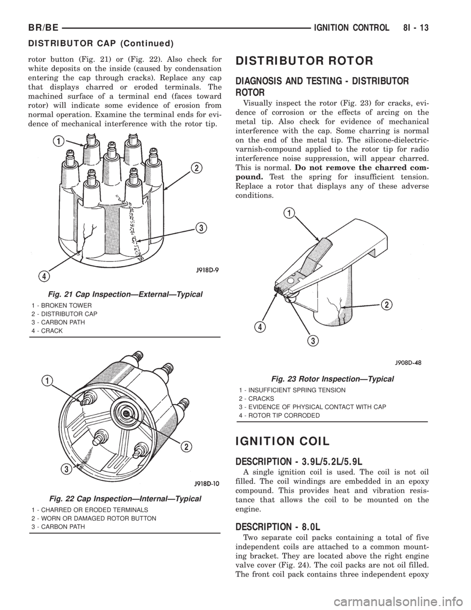
rotor button (Fig. 21) or (Fig. 22). Also check for
white deposits on the inside (caused by condensation
entering the cap through cracks). Replace any cap
that displays charred or eroded terminals. The
machined surface of a terminal end (faces toward
rotor) will indicate some evidence of erosion from
normal operation. Examine the terminal ends for evi-
dence of mechanical interference with the rotor tip.DISTRIBUTOR ROTOR
DIAGNOSIS AND TESTING - DISTRIBUTOR
ROTOR
Visually inspect the rotor (Fig. 23) for cracks, evi-
dence of corrosion or the effects of arcing on the
metal tip. Also check for evidence of mechanical
interference with the cap. Some charring is normal
on the end of the metal tip. The silicone-dielectric-
varnish-compound applied to the rotor tip for radio
interference noise suppression, will appear charred.
This is normal.Do not remove the charred com-
pound.Test the spring for insufficient tension.
Replace a rotor that displays any of these adverse
conditions.
IGNITION COIL
DESCRIPTION - 3.9L/5.2L/5.9L
A single ignition coil is used. The coil is not oil
filled. The coil windings are embedded in an epoxy
compound. This provides heat and vibration resis-
tance that allows the coil to be mounted on the
engine.
DESCRIPTION - 8.0L
Two separate coil packs containing a total of five
independent coils are attached to a common mount-
ing bracket. They are located above the right engine
valve cover (Fig. 24). The coil packs are not oil filled.
The front coil pack contains three independent epoxy
Fig. 21 Cap InspectionÐExternalÐTypical
1 - BROKEN TOWER
2 - DISTRIBUTOR CAP
3 - CARBON PATH
4 - CRACK
Fig. 22 Cap InspectionÐInternalÐTypical
1 - CHARRED OR ERODED TERMINALS
2 - WORN OR DAMAGED ROTOR BUTTON
3 - CARBON PATH
Fig. 23 Rotor InspectionÐTypical
1 - INSUFFICIENT SPRING TENSION
2 - CRACKS
3 - EVIDENCE OF PHYSICAL CONTACT WITH CAP
4 - ROTOR TIP CORRODED
BR/BEIGNITION CONTROL 8I - 13
DISTRIBUTOR CAP (Continued)
Page 553 of 2889
SPARK PLUG
DESCRIPTION
The 3.9L V-6 and 5.2L/5.9L V-8 engines use resis-
tor type spark plugs. The 8.0L V-10 engine uses
inductive type spark plugs.
Spark plug resistance values range from 6,000 to
20,000 ohms (when checked with at least a 1000 volt
spark plug tester).Do not use an ohmmeter to
check the resistance values of the spark plugs.
Inaccurate readings will result.
OPERATION
To prevent possible pre-ignition and/or mechanical
engine damage, the correct type/heat range/number
spark plug must be used.
Always use the recommended torque when tighten-
ing spark plugs. Incorrect torque can distort the
spark plug and change plug gap. It can also pull the
plug threads and do possible damage to both the
spark plug and the cylinder head.
Remove the spark plugs and examine them for
burned electrodes and fouled, cracked or broken por-
celain insulators. Keep plugs arranged in the order
in which they were removed from the engine. A sin-gle plug displaying an abnormal condition indicates
that a problem exists in the corresponding cylinder.
Replace spark plugs at the intervals recommended in
Group O, Lubrication and Maintenance
Spark plugs that have low mileage may be cleaned
and reused if not otherwise defective, carbon or oil
fouled. Also refer to Spark Plug Conditions.
CAUTION: Never use a motorized wire wheel brush
to clean the spark plugs. Metallic deposits will
remain on the spark plug insulator and will cause
plug misfire.
DIAGNOSIS AND TESTING - SPARK PLUG
CONDITIONS
NORMAL OPERATING
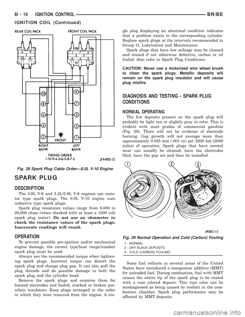
The few deposits present on the spark plug will
probably be light tan or slightly gray in color. This is
evident with most grades of commercial gasoline
(Fig. 29). There will not be evidence of electrode
burning. Gap growth will not average more than
approximately 0.025 mm (.001 in) per 3200 km (2000
miles) of operation. Spark plugs that have normal
wear can usually be cleaned, have the electrodes
filed, have the gap set and then be installed.
Some fuel refiners in several areas of the United
States have introduced a manganese additive (MMT)
for unleaded fuel. During combustion, fuel with MMT
causes the entire tip of the spark plug to be coated
with a rust colored deposit. This rust color can be
misdiagnosed as being caused by coolant in the com-
bustion chamber. Spark plug performance may be
affected by MMT deposits.
Fig. 28 Spark Plug Cable OrderÐ8.0L V-10 Engine
Fig. 29 Normal Operation and Cold (Carbon) Fouling
1 - NORMAL
2 - DRY BLACK DEPOSITS
3 - COLD (CARBON) FOULING
8I - 16 IGNITION CONTROLBR/BE
IGNITION COIL (Continued)
Page 556 of 2889
CLEANING
The plugs may be cleaned using commercially
available spark plug cleaning equipment. After clean-
ing, file center electrode flat with a small point file or
jewelers file before adjusting gap.
CAUTION: Never use a motorized wire wheel brush
to clean spark plugs. Metallic deposits will remain
on spark plug insulator and will cause plug misfire.
INSTALLATION
Special care should be taken when installing spark
plugs into the cylinder head spark plug wells. Be
sure the plugs do not drop into the plug wells as elec-
trodes can be damaged.
Always tighten spark plugs to the specified torque.
Over tightening can cause distortion resulting in a
change in the spark plug gap or a cracked porcelain
insulator.
When replacing the spark plug and ignition coil
cables, route the cables correctly and secure them in
the appropriate retainers. Failure to route the cables
properly can cause the radio to reproduce ignition
noise. It could cause cross ignition of the spark plugs
or short circuit the cables to ground.
(1) Start the spark plug into the cylinder head by
hand to avoid cross threading.
(2) Tighten spark plugs to 35-41 N´m (26-30 ft.
lbs.) torque.
(3) Install spark plug cables over spark plugs.
SPARK PLUG CABLE
DESCRIPTION
Spark plug cables are sometimes referred to as sec-
ondary ignition wires.
OPERATION
The spark plug cables transfer electrical current
from the ignition coil(s) and/or distributor, to individ-
ual spark plugs at each cylinder. The resistive spark
plug cables are of nonmetallic construction. The
cables provide suppression of radio frequency emis-
sions from the ignition system.
DIAGNOSIS AND TESTING - SPARK PLUG
CABLES
Cable routing is important on certain engines. To
prevent possible ignition crossfire, be sure the cables
are clipped into the plastic routing looms. Try to pre-
vent any one cable from contacting another. Before
removing cables, note their original location and
routing. Never allow one cable to be twisted around
another.
Check the spark plug cable connections for good
contact at the coil(s), distributor cap towers, and
spark plugs. Terminals should be fully seated. The
insulators should be in good condition and should fit
tightly on the coil, distributor and spark plugs. Spark
plug cables with insulators that are cracked or torn
must be replaced.
Clean high voltage ignition cables with a cloth
moistened with a non-flammable solvent. Wipe the
cables dry. Check for brittle or cracked insulation.
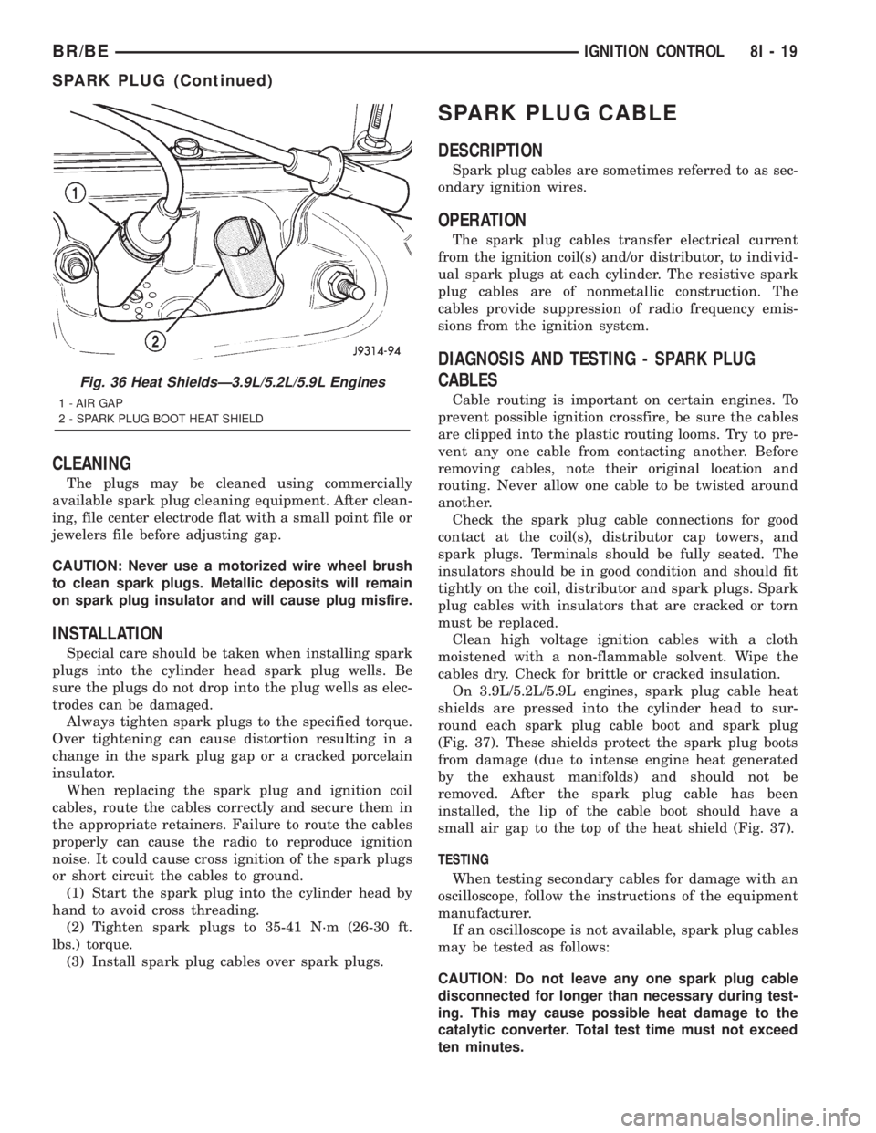
On 3.9L/5.2L/5.9L engines, spark plug cable heat
shields are pressed into the cylinder head to sur-
round each spark plug cable boot and spark plug
(Fig. 37). These shields protect the spark plug boots
from damage (due to intense engine heat generated
by the exhaust manifolds) and should not be
removed. After the spark plug cable has been
installed, the lip of the cable boot should have a
small air gap to the top of the heat shield (Fig. 37).
TESTING
When testing secondary cables for damage with an
oscilloscope, follow the instructions of the equipment
manufacturer.
If an oscilloscope is not available, spark plug cables
may be tested as follows:
CAUTION: Do not leave any one spark plug cable
disconnected for longer than necessary during test-
ing. This may cause possible heat damage to the
catalytic converter. Total test time must not exceed
ten minutes.
Fig. 36 Heat ShieldsÐ3.9L/5.2L/5.9L Engines
1 - AIR GAP
2 - SPARK PLUG BOOT HEAT SHIELD
BR/BEIGNITION CONTROL 8I - 19
SPARK PLUG (Continued)
Page 557 of 2889
With the engine running, remove spark plug cable
from spark plug (one at a time) and hold next to a
good engine ground. If the cable and spark plug are
in good condition, the engine rpm should drop and
the engine will run poorly. If engine rpm does not
drop, the cable and/or spark plug may not be operat-
ing properly and should be replaced. Also check
engine cylinder compression.
With the engine not running, connect one end of a
test probe to a good ground. Start the engine and run
the other end of the test probe along the entire
length of all spark plug cables. If cables are cracked
or punctured, there will be a noticeable spark jump
from the damaged area to the test probe. The cable
running from the ignition coil to the distributor cap
can be checked in the same manner. Cracked, dam-
aged or faulty cables should be replaced with resis-
tance type cable. This can be identified by the words
ELECTRONIC SUPPRESSION printed on the cable
jacket.
Use an ohmmeter to test for open circuits, exces-
sive resistance or loose terminals. If equipped,
remove the distributor cap from the distributor.Do
not remove cables from cap.Remove cable from
spark plug. Connect ohmmeter to spark plug termi-
nal end of cable and to corresponding electrode in
distributor cap. Resistance should be 250 to 1000
Ohms per inch of cable. If not, remove cable from dis-
tributor cap tower and connect ohmmeter to the ter-
minal ends of cable. If resistance is not within
specifications as found in the SPARK PLUG CABLE
RESISTANCE chart, replace the cable. Test all spark
plug cables in this manner.
SPARK PLUG CABLE RESISTANCE
MINIMUM MAXIMUM
250 Ohms Per Inch 1000 Ohms Per Inch
3000 Ohms Per Foot 12,000 Ohms Per Foot
To test ignition coil-to-distributor cap cable, do not
remove the cable from the cap. Connect ohmmeter to
rotor button (center contact) of distributor cap and
terminal at ignition coil end of cable. If resistance is
not within specifications as found in the Spark Plug
Cable Resistance chart, remove the cable from the
distributor cap. Connect the ohmmeter to the termi-
nal ends of the cable. If resistance is not within spec-
ifications as found in the Spark Plug Cable
Resistance chart, replace the cable. Inspect the igni-
tion coil tower for cracks, burns or corrosion.
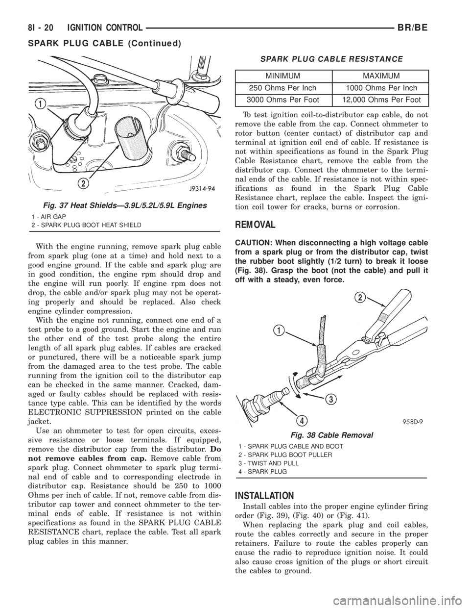
REMOVAL
CAUTION: When disconnecting a high voltage cable
from a spark plug or from the distributor cap, twist
the rubber boot slightly (1/2 turn) to break it loose
(Fig. 38). Grasp the boot (not the cable) and pull it
off with a steady, even force.
INSTALLATION
Install cables into the proper engine cylinder firing
order (Fig. 39), (Fig. 40) or (Fig. 41).
When replacing the spark plug and coil cables,
route the cables correctly and secure in the proper
retainers. Failure to route the cables properly can
cause the radio to reproduce ignition noise. It could
also cause cross ignition of the plugs or short circuit
the cables to ground.
Fig. 37 Heat ShieldsÐ3.9L/5.2L/5.9L Engines
1 - AIR GAP
2 - SPARK PLUG BOOT HEAT SHIELD
Fig. 38 Cable Removal
1 - SPARK PLUG CABLE AND BOOT
2 - SPARK PLUG BOOT PULLER
3 - TWIST AND PULL
4 - SPARK PLUG
8I - 20 IGNITION CONTROLBR/BE
SPARK PLUG CABLE (Continued)
Page 560 of 2889
INSTRUMENT CLUSTER
TABLE OF CONTENTS
page page
INSTRUMENT CLUSTER
DESCRIPTION............................2
OPERATION.............................3
DIAGNOSIS AND TESTING..................6
INSTRUMENT CLUSTER..................6
REMOVAL..............................10
DISASSEMBLY...........................11
ASSEMBLY.............................13
INSTALLATION...........................14
ABS INDICATOR
DESCRIPTION...........................14
OPERATION.............................14
AIRBAG INDICATOR
DESCRIPTION...........................15
OPERATION.............................15
BRAKE/PARK BRAKE INDICATOR
DESCRIPTION...........................16
OPERATION.............................16
DIAGNOSIS AND TESTING.................16
BRAKE INDICATOR.....................16
CHECK GAUGES INDICATOR
DESCRIPTION...........................17
OPERATION.............................17
CRUISE INDICATOR
DESCRIPTION...........................18
OPERATION.............................18
ENGINE TEMPERATURE GAUGE
DESCRIPTION...........................19
OPERATION.............................19
FUEL GAUGE
DESCRIPTION...........................20
OPERATION.............................20
GEAR SELECTOR INDICATOR
DESCRIPTION...........................21
OPERATION.............................21
HIGH BEAM INDICATOR
DESCRIPTION...........................21
OPERATION.............................22
DIAGNOSIS AND TESTING.................22
HIGH BEAM INDICATOR.................22
LOW FUEL INDICATOR
DESCRIPTION...........................23
OPERATION.............................23
MALFUNCTION INDICATOR LAMP (MIL)
DESCRIPTION...........................24
OPERATION.............................24
ODOMETER
DESCRIPTION...........................24
OPERATION.............................25OIL PRESSURE GAUGE
DESCRIPTION...........................25
OPERATION.............................26
OVERDRIVE OFF INDICATOR
DESCRIPTION...........................27
OPERATION.............................27
SEATBELT INDICATOR
DESCRIPTION...........................27
OPERATION.............................27
SERVICE REMINDER INDICATOR
DESCRIPTION...........................28
OPERATION.............................28
SHIFT INDICATOR (TRANSFER CASE)
DESCRIPTION...........................29
OPERATION.............................29
DIAGNOSIS AND TESTING.................29
FOUR-WHEEL DRIVE INDICATOR..........29
SPEEDOMETER
DESCRIPTION...........................30
OPERATION.............................30
TACHOMETER
DESCRIPTION...........................30
OPERATION.............................31
TRANSMISSION OVERTEMP INDICATOR
DESCRIPTION...........................31
OPERATION.............................31
TURN SIGNAL INDICATORS
DESCRIPTION...........................32
OPERATION.............................32
DIAGNOSIS AND TESTING.................32
TURN SIGNAL INDICATORS..............32
UPSHIFT INDICATOR
DESCRIPTION...........................33
OPERATION.............................33
VOLTAGE GAUGE
DESCRIPTION...........................33
OPERATION.............................34
WAIT-TO-START INDICATOR
DESCRIPTION...........................34
OPERATION.............................35
WASHER FLUID INDICATOR
DESCRIPTION...........................35
OPERATION.............................35
DIAGNOSIS AND TESTING.................36
WASHER FLUID INDICATOR..............36
WATER-IN-FUEL INDICATOR
DESCRIPTION...........................36
OPERATION.............................37
BR/BEINSTRUMENT CLUSTER 8J - 1
Page 562 of 2889
²Check Gauges Indicator
²Cruise Indicator (Odometer VFD)
²Four-Wheel Drive Indicator
²High Beam Indicator
²Low Fuel Indicator
²Washer Fluid Indicator
²Malfunction Indicator Lamp (MIL)
²Overdrive-Off Indicator
²Seatbelt Indicator
²Service Reminder Indicator (SRI)
²Transmission Overtemp Indicator
²Turn Signal (Right and Left) Indicators
²Upshift Indicator
²Wait-To-Start Indicator (Diesel Only)
²Water-In-Fuel Indicator (Diesel Only)
Some of these indicators are either programmable
or automatically configured when the EMIC is con-
nected to the vehicle electrical system. This feature
allows those indicators to be activated or deactivated
for compatibility with certain optional equipment.
The EMIC also includes a provision for mounting the
automatic transmission gear selector indicator in the
lower right corner of the cluster. The spring-loaded,
cable driven, mechanical gear selector indicator gives
an indication of the transmission gear that has been
selected with the automatic transmission gear selec-
tor lever. The gear selector indicator pointer is easily
visible through an opening provided in the front of
the cluster overlay, and is also lighted by the cluster
illumination lamps for visibility at night. Models
equipped with a manual transmission have a block-
out plate installed in place of the gear selector indi-
cator.
Cluster illumination is accomplished by adjustable
incandescent back lighting, which illuminates the
gauges for visibility when the exterior lighting is
turned on. The EMIC high beam indicator, turn sig-
nal indicators, and wait-to-start indicator are also
illuminated by dedicated incandescent bulbs. The
remaining indicators in the EMIC are each illumi-
nated by a dedicated Light Emitting Diode (LED)
that is soldered onto the electronic circuit board.
Each of the incandescent bulbs is secured by an inte-
gral bulb holder to the electronic circuit board from
the back of the cluster housing.
Hard wired circuitry connects the EMIC to the
electrical system of the vehicle. These hard wired cir-
cuits are integral to several wire harnesses, which
are routed throughout the vehicle and retained by
many different methods. These circuits may be con-
nected to each other, to the vehicle electrical system
and to the EMIC through the use of a combination of
soldered splices, splice block connectors, and many
different types of wire harness terminal connectors
and insulators. Refer to the appropriate wiring infor-
mation. The wiring information includes wiring dia-grams, proper wire and connector repair procedures,
further details on wire harness routing and reten-
tion, as well as pin-out and location views for the
various wire harness connectors, splices and grounds.
The EMIC modules for this model are serviced only
as complete units. The EMIC module cannot be
adjusted or repaired. If a gauge, an LED indicator,
the VFD, the electronic circuit board, the circuit
board hardware, the cluster overlay, or the EMIC
housing are damaged or faulty, the entire EMIC mod-
ule must be replaced. The cluster lens and hood unit,
the rear cluster housing cover, the automatic trans-
mission gear selector indicator, and the incandescent
lamp bulbs with holders are available for individual
service replacement.
OPERATION
The ElectroMechanical Instrument Cluster (EMIC)
is designed to allow the vehicle operator to monitor
the conditions of many of the vehicle components and
operating systems. The gauges and indicators in the
EMIC provide valuable information about the various
standard and optional powertrains, fuel and emis-
sions systems, cooling systems, lighting systems,
safety systems and many other convenience items.
The EMIC is installed in the instrument panel so
that all of these monitors can be easily viewed by the
vehicle operator when driving, while still allowing
relative ease of access for service. The microproces-
sor-based EMIC hardware and software uses various
inputs to control the gauges and indicators visible on
the face of the cluster. Some of these inputs are hard
wired, but most are in the form of electronic mes-
sages that are transmitted by other electronic mod-
ules over the Chrysler Collision Detection (CCD) data
bus network. (Refer to 8 - ELECTRICAL/ELEC-
TRONIC CONTROL MODULES/COMMUNICATION
- OPERATION).
The EMIC microprocessor smooths the input data
using algorithms to provide gauge readings that are
accurate, stable and responsive to operating condi-
tions. These algorithms are designed to provide
gauge readings during normal operation that are con-
sistent with customer expectations. However, when
abnormal conditions exist, such as low/high battery
voltage, low oil pressure, or high coolant tempera-
ture, the algorithm drives the gauge pointer to an
extreme position and the microprocessor turns on the
Check Gauges indicator to provide a distinct visual
indication of a problem to the vehicle operator. The
instrument cluster circuitry may also generate a
hard wired chime tone request to the Central Timer
Module (CTM) when it monitors certain conditions or
inputs, in order to provide the vehicle operator with
an audible alert.
BR/BEINSTRUMENT CLUSTER 8J - 3
INSTRUMENT CLUSTER (Continued)
Page 577 of 2889
²Engine Oil Pressure Low Message- Each
time the cluster receives a message from the PCM
indicating the engine oil pressure of a gasoline
engine is about 3.45 kPa (0.5 psi) or lower, or a diesel
engine is about 51.71 kPa (7.5 psi) or lower, the
check gauges indicator will be illuminated. The indi-
cator remains illuminated until the cluster receives a
message from the PCM indicating that the engine oil
pressure of a gasoline engine is above 3.45 kPa (0.5
psi), a diesel engine is above 51.71 kPa (7.5 psi), or
until the ignition switch is turned to the Off position,
whichever occurs first. The cluster will only turn the
indicator on in response to an engine oil pressure low
message if the engine speed is greater than zero.
²System Voltage Low Message- Each time the
cluster receives a message from the PCM indicating
the electrical system voltage is less than 11.5 volts,
the check gauges indicator will be illuminated. The
indicator remains illuminated until the cluster
receives a message from the PCM indicating the elec-
trical system voltage is greater than 12.0 volts (but
less than 16.6 volts), or until the ignition switch is
turned to the Off position, whichever occurs first.
²System Voltage High Message- Each time
the cluster receives a message from the PCM indicat-
ing the electrical system voltage is greater than 16.6
volts, the check gauges indicator will be illuminated.
The indicator remains illuminated until the cluster
receives a message from the PCM indicating the elec-
trical system voltage is less than 16.1 volts (but
greater than 11.5 volts), or until the ignition switch
is turned to the Off position, whichever occurs first.
²Actuator Test- Each time the cluster is put
through the actuator test, the indicator will be
turned on during the bulb check portion of the test to
confirm the functionality of the LED and the cluster
control circuitry.
The PCM continually monitors the engine temper-
ature, oil pressure, and electrical system voltage,
then sends the proper messages to the instrument
cluster. For further diagnosis of the check gauges
indicator or the instrument cluster circuitry that con-
trols the LED, (Refer to 8 - ELECTRICAL/INSTRU-
MENT CLUSTER - DIAGNOSIS AND TESTING).
For proper diagnosis of the PCM, the CCD data bus,
or the message inputs to the instrument cluster that
control the check gauges indicator, a DRBIIItscan
tool is required. Refer to the appropriate diagnostic
information.
CRUISE INDICATOR
DESCRIPTION
A cruise indicator is standard equipment on all
instrument clusters. However, on vehicles notequipped with the optional speed control system, this
indicator is electronically disabled. The cruise indica-
tor consists of the word ªCRUISEº, which appears in
the lower portion of the odometer/trip odometer Vac-
uum-Fluorescent Display (VFD). The VFD is part of
the cluster electronic circuit board, and is visible
through a cutout located in the lower left corner of
the cluster overlay. The dark lens of the VFD pre-
vents the indicator from being clearly visible when it
is not illuminated. The word ªCRUISEº appears in
an amber color and at the same lighting level as the
odometer/trip odometer information when it is illumi-
nated by the instrument cluster electronic circuit
board. The cruise indicator lamp is serviced as a unit
with the VFD in the instrument cluster.
OPERATION
The cruise indicator gives an indication to the vehi-
cle operator when the speed control system is turned
On, regardless of whether the speed control is
engaged. This indicator is controlled by the instru-
ment cluster circuit board based upon the cluster
programming and electronic messages received by
the cluster from the Powertrain Control Module
(PCM) over the Chrysler Collision Detection (CCD)
data bus. The cruise indicator receives battery cur-
rent on the instrument cluster electronic circuit
board through the fused ignition switch output (st-
run) circuit whenever the ignition switch is in the On
or Start positions; therefore, the indicator will always
be off when the ignition switch is in any position
except On or Start. The indicator only illuminates
when it is switched to ground by the instrument clus-
ter circuitry. The instrument cluster will turn on the
cruise indicator for the following reasons:
²Bulb Test- Each time the ignition switch is
turned to the On position the cruise indicator is illu-
minated for about two seconds as a bulb test.
²Cruise Lamp-On Message- Each time the
cluster receives a cruise lamp-on message from the
PCM indicating the speed control system has been
turned On, the cruise indicator is illuminated. The
indicator remains illuminated until the cluster
receives a cruise lamp-off message from the PCM or
until the ignition switch is turned to the Off position,
whichever occurs first.
²Actuator Test- Each time the cluster is put
through the actuator test, the cruise indicator will be
turned on during the VFD portion of the test to con-
firm the functionality of the VFD, and again during
the bulb check portion of the test to confirm the func-
tionality of the cluster control circuitry.
The PCM continually monitors the speed control
switches to determine the proper outputs to the
speed control servo. The PCM then sends the proper
cruise indicator lamp-on and lamp-off messages to
8J - 18 INSTRUMENT CLUSTERBR/BE
CHECK GAUGES INDICATOR (Continued)