2001 DODGE RAM oil filter
[x] Cancel search: oil filterPage 1307 of 2889
DIAGNOSIS AND TESTINGÐENGINE OIL
LEAKS
Begin with a through visual inspection of the
engine, particularly at the area of the suspected leak.
If an oil leak source is not readily identifiable, the
following steps should be followed:
(1) Do not clean or degrease the engine at this
time because some solvents may cause rubber to
swell, temporarily stopping the leak.
(2) Add an oil-soluble dye (use as recommended by
manufacturer). Start the engine and let idle for
approximately 15 minutes. Check the oil dipstick to
be sure the dye is thoroughly mixed as indicated
with a bright yellow color under a black light source.
(3) Using a black light, inspect the entire engine
for fluorescent dye, particularly at the suspected area
of oil leak. If the oil leak is found and identified,
repair per service manual instructions.
(4) If dye is not observed, drive the vehicle at var-
ious speeds for approximately 24km (15 miles), and
repeat previous step.
(5) If the oil leak source is not positively identified
at this time, proceed with the air leak detection test
method as follows:
(6) Disconnect the breather cap to air cleaner hose
at the breather cap end. Cap or plug breather cap
nipple.
(7) Remove the PCV valve from the cylinder head
cover. Cap or plug the PCV valve grommet.
(8) Attach an air hose with pressure gauge and
regulator to the dipstick tube.
CAUTION: Do not subject the engine assembly to
more than 20.6 kpa (3 PSI) of test pressure.
(9) Gradually apply air pressure from 1 psi to 2.5
psi maximum while applying soapy water at the sus-
pected source. Adjust the regulator to the suitable
test pressure that provide the best bubbles which
will pinpoint the leak source. If the oil leak is
detected and identified, repair per service manual
procedures.
(10) If the leakage occurs at the rear oil seal area,
refer to the section, Inspection for Rear Seal Area
Leak.
(11) If no leaks are detected, turn off the air sup-
ply and remove the air hose and all plugs and caps.
Install the PCV valve and breather cap hose. Proceed
to next step.
(12) Clean the oil off the suspect oil leak area
using a suitable solvent. Drive the vehicle at various
speeds approximately 24 km (15 miles). Inspect the
engine for signs of an oil leak by using a black light.
DIAGNOSIS AND TESTINGÐENGINE OIL
PRESSURE
(1) Remove oil pressure sending unit.
(2) Install Oil Pressure Line and Gauge Tool
C-3292. Start engine and record pressure. (Refer to 9
- ENGINE - SPECIFICATIONS).
OIL
STANDARD PROCEDUREÐENGINE OIL
OIL LEVEL INDICATOR (DIPSTICK)
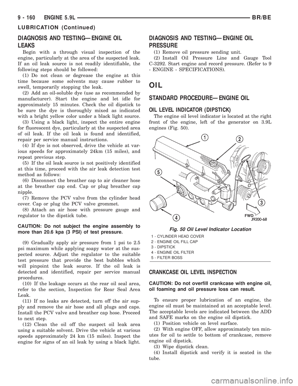
The engine oil level indicator is located at the right
front of the engine, left of the generator on 3.9L
engines (Fig. 50).
CRANKCASE OIL LEVEL INSPECTION
CAUTION: Do not overfill crankcase with engine oil,
oil foaming and oil pressure loss can result.
To ensure proper lubrication of an engine, the
engine oil must be maintained at an acceptable level.
The acceptable levels are indicated between the ADD
and SAFE marks on the engine oil dipstick.
(1) Position vehicle on level surface.
(2) With engine OFF, allow approximately ten min-
utes for oil to settle to bottom of crankcase, remove
engine oil dipstick.
(3) Wipe dipstick clean.
(4) Install dipstick and verify it is seated in the
tube.
Fig. 50 Oil Level Indicator Location
1 - CYLINDER HEAD COVER
2 - ENGINE OIL FILL CAP
3 - DIPSTICK
4 - ENGINE OIL FILTER
5 - FILTER BOSS
9 - 160 ENGINE 5.9LBR/BE
LUBRICATION (Continued)
Page 1308 of 2889
(5) Remove dipstick, with handle held above the
tip, take oil level reading.
(6) Add oil only if level is below the ADD mark on
dipstick.
ENGINE OIL CHANGE
Change engine oil at mileage and time intervals
described in the Maintenance Schedule. This infor-
mation can be found in the owner's manual.
TO CHANGE ENGINE OIL
Run engine until achieving normal operating tem-
perature.
(1) Position the vehicle on a level surface and turn
engine off.
(2) Hoist vehicle.
(3) Remove oil fill cap.
(4) Place a suitable drain pan under crankcase
drain.
(5) Remove drain plug from crankcase and allow
oil to drain into pan. Inspect drain plug threads for
stretching or other damage. Replace drain plug and
gasket if damaged.
(6) Install drain plug in crankcase.
(7) Change oil filter (Refer to 9 - ENGINE/LUBRI-
CATION/OIL FILTER - REMOVAL).
(8) Lower vehicle and fill crankcase with specified
type (Refer to LUBRICATION & MAINTENANCE/
FLUID TYPES - DESCRIPTION) and amount of
engine oil (Refer to LUBRICATION & MAINTE-
NANCE - SPECIFICATIONS).
(9) Install oil fill cap.
(10) Start engine and inspect for leaks.
(11) Stop engine and inspect oil level.
OIL FILTER
REMOVAL
All engines are equipped with a high quality full-
flow, disposable type oil filter. DaimlerChrysler Cor-
poration recommends a Mopartor equivalent oil
filter be used.
(1) Position a drain pan under the oil filter.
(2) Using a suitable oil filter wrench loosen filter.
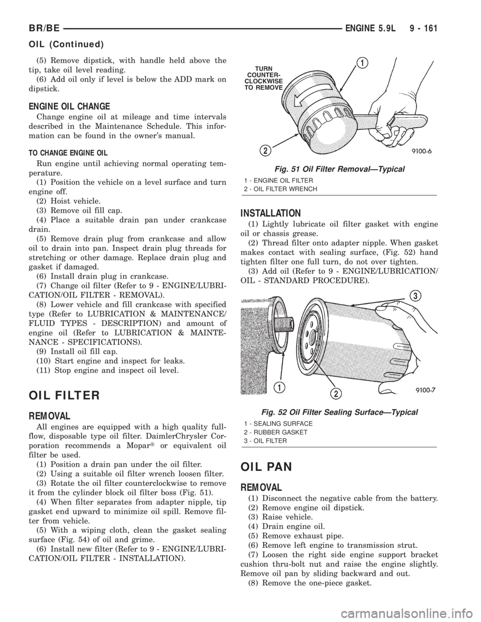
(3) Rotate the oil filter counterclockwise to remove
it from the cylinder block oil filter boss (Fig. 51).
(4) When filter separates from adapter nipple, tip
gasket end upward to minimize oil spill. Remove fil-
ter from vehicle.
(5) With a wiping cloth, clean the gasket sealing
surface (Fig. 54) of oil and grime.
(6) Install new filter (Refer to 9 - ENGINE/LUBRI-
CATION/OIL FILTER - INSTALLATION).
INSTALLATION
(1) Lightly lubricate oil filter gasket with engine
oil or chassis grease.
(2) Thread filter onto adapter nipple. When gasket
makes contact with sealing surface, (Fig. 52) hand
tighten filter one full turn, do not over tighten.
(3) Add oil (Refer to 9 - ENGINE/LUBRICATION/
OIL - STANDARD PROCEDURE).
OIL PAN
REMOVAL
(1) Disconnect the negative cable from the battery.
(2) Remove engine oil dipstick.
(3) Raise vehicle.
(4) Drain engine oil.
(5) Remove exhaust pipe.
(6) Remove left engine to transmission strut.
(7) Loosen the right side engine support bracket
cushion thru-bolt nut and raise the engine slightly.
Remove oil pan by sliding backward and out.
(8) Remove the one-piece gasket.
Fig. 51 Oil Filter RemovalÐTypical
1 - ENGINE OIL FILTER
2 - OIL FILTER WRENCH
Fig. 52 Oil Filter Sealing SurfaceÐTypical
1 - SEALING SURFACE
2 - RUBBER GASKET
3 - OIL FILTER
BR/BEENGINE 5.9L 9 - 161
OIL (Continued)
Page 1319 of 2889
LUBRICATION
DESCRIPTION..........................214
OPERATION............................214
DIAGNOSIS AND TESTING................215
ENGINE OIL LEAKS....................215
ENGINE OIL PRESSURE................215
OIL
STANDARD PROCEDURE.................217
ENGINE OIL..........................217
OIL FILTER
REMOVAL.............................218
INSTALLATION..........................218
OIL PAN
REMOVAL.............................218
CLEANING.............................218
INSPECTION...........................219
INSTALLATION..........................219
OIL PUMP
REMOVAL.............................219
CLEANING.............................220
INSPECTION...........................220
INSTALLATION..........................221INTAKE MANIFOLD
DESCRIPTION..........................222
DIAGNOSIS AND TESTING................222
INTAKE MANIFOLD LEAKAGE............222
REMOVAL.............................222
CLEANING.............................223
INSPECTION...........................223
INSTALLATION..........................223
EXHAUST MANIFOLD
DESCRIPTION..........................224
OPERATION............................224
REMOVAL.............................225
CLEANING.............................225
INSPECTION...........................225
INSTALLATION..........................225
TIMING BELT / CHAIN COVER(S)
REMOVAL.............................225
INSTALLATION..........................226
TIMING BELT/CHAIN AND SPROCKETS
REMOVAL.............................226
INSPECTION...........................227
INSTALLATION..........................227
ENGINE 8.0L
DESCRIPTION
The 8.0 Liter (488 CID) ten-cylinder engine is a
V-Type lightweight, single cam, overhead valveengine with hydraulic roller tappets. This engine is
designed for unleaded fuel.
Engine lubrication system consists of a gerotor type
oil pump mounted in the timing chain cover and driven
by the crankshaft. The V-10 uses a full flow oil filter.
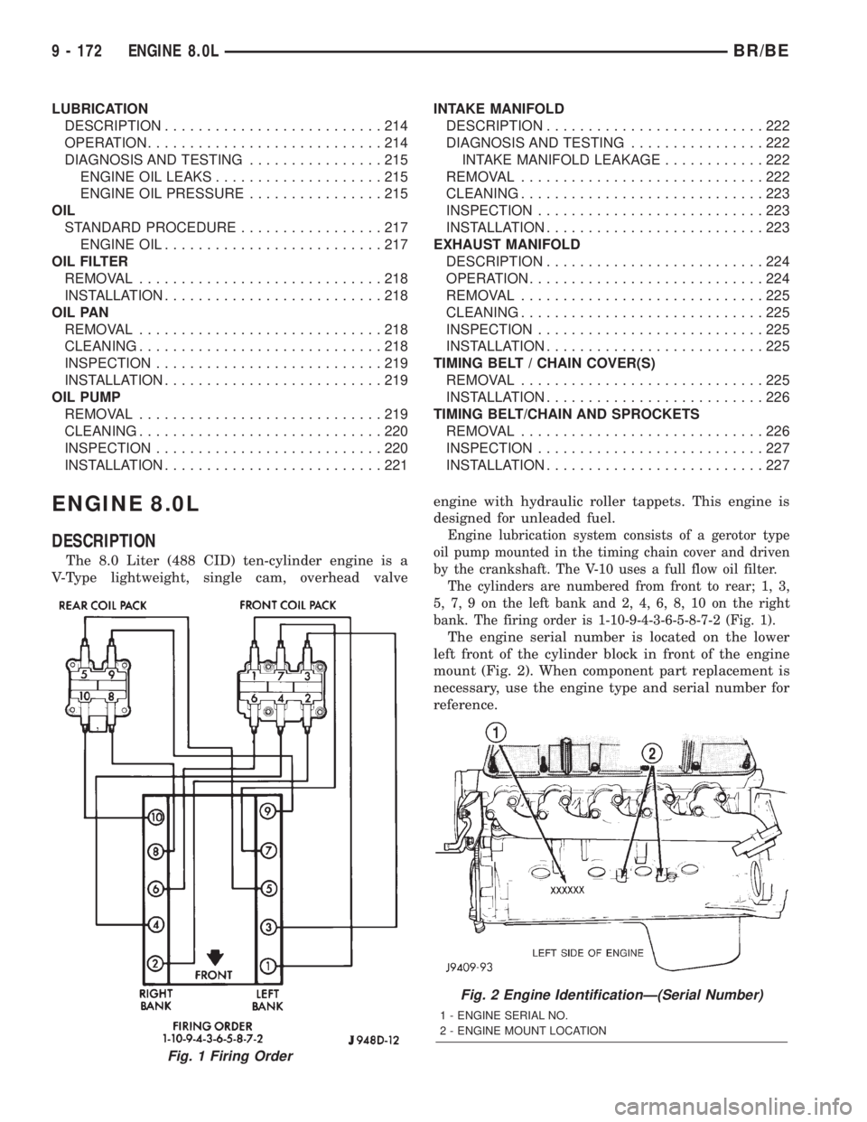
The cylinders are numbered from front to rear; 1, 3,
5, 7, 9 on the left bank and 2, 4, 6, 8, 10 on the right
bank. The firing order is 1-10-9-4-3-6-5-8-7-2 (Fig. 1).
The engine serial number is located on the lower
left front of the cylinder block in front of the engine
mount (Fig. 2). When component part replacement is
necessary, use the engine type and serial number for
reference.
Fig. 1 Firing Order
Fig. 2 Engine IdentificationÐ(Serial Number)
1 - ENGINE SERIAL NO.
2 - ENGINE MOUNT LOCATION
9 - 172 ENGINE 8.0LBR/BE
Page 1321 of 2889
CONDITION POSSIBLE CAUSES CORRECTION
ENGINE LOSS OF POWER 1. Worn or burned distributor rotor 1. Install new distributor rotor
2. Worn distributor shaft 2. Remove and repair distributor
(Refer to 8 - ELECTRICAL/IGNITION
CONTROL/DISTRIBUTOR -
REMOVAL).
3. Worn or incorrect gapped spark
plugs3. Clean plugs and set gap. (Refer to
8 - ELECTRICAL/IGNITION
CONTROL/SPARK PLUG -
CLEANING).
4. Dirt or water in fuel system 4. Clean system and replace fuel filter
5. Faulty fuel pump 5. Install new fuel pump
6. Incorrect valve timing 6. Correct valve timing
7. Blown cylinder head gasket 7. Install new cylinder head gasket
8. Low compression 8. Test cylinder compression (Refer to
9 - ENGINE - DIAGNOSIS AND
TESTING).
9. Burned, warped, or pitted valves 9. Install/Reface valves as necessary
10. Plugged or restricted exhaust
system10. Install new parts as necessary
11. Faulty ignition cables 11. Replace any cracked or shorted
cables
12. Faulty ignition coil 12. Test and replace, as necessary
(Refer to 8 - ELECTRICAL/IGNITION
CONTROL/IGNITION COIL -
REMOVAL).
ENGINE STALLS OR ROUGH IDLE 1. Carbon build-up on throttle plate 1. Remove throttle body and
de-carbon. (Refer to 14 - FUEL
SYSTEM/FUEL INJECTION/
THROTTLE BODY - REMOVAL).
2. Engine idle speed too low 2. Check Idle Air Control circuit.
(Refer to 14 - FUEL SYSTEM/FUEL
INJECTION/IDLE AIR CONTROL
MOTOR - DESCRIPTION)
3. Worn or incorrectly gapped spark
plugs3. Replace or clean and re-gap spark
plugs (Refer to 8 - ELECTRICAL/
IGNITION CONTROL/SPARK PLUG -
CLEANING)
4. Worn or burned distributor rotor 4. Install new distributor rotor
5. Spark plug cables defective or
crossed5. Check for correct firing order or
replace spark plug cables. (Refer to 8
- ELECTRICAL/IGNITION CONTROL/
SPARK PLUG CABLE - DIAGNOSIS
AND TESTING)
6. Faulty coil 6. Test and replace, if necessary
(Refer to 8 - ELECTRICAL/IGNITION
CONTROL/IGNITION COIL -
REMOVAL)
9 - 174 ENGINE 8.0LBR/BE
ENGINE 8.0L (Continued)
Page 1323 of 2889
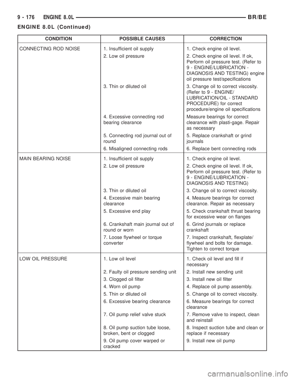
CONDITION POSSIBLE CAUSES CORRECTION
CONNECTING ROD NOISE 1. Insufficient oil supply 1. Check engine oil level.
2. Low oil pressure 2. Check engine oil level. If ok,
Perform oil pressure test. (Refer to
9 - ENGINE/LUBRICATION -
DIAGNOSIS AND TESTING) engine
oil pressure test/specifications
3. Thin or diluted oil 3. Change oil to correct viscosity.
(Refer to 9 - ENGINE/
LUBRICATION/OIL - STANDARD
PROCEDURE) for correct
procedure/engine oil specifications
4. Excessive connecting rod
bearing clearanceMeasure bearings for correct
clearance with plasti-gage. Repair
as necessary
5. Connecting rod journal out of
round5. Replace crankshaft or grind
journals
6. Misaligned connecting rods 6. Replace bent connecting rods
MAIN BEARING NOISE 1. Insufficient oil supply 1. Check engine oil level.
2. Low oil pressure 2. Check engine oil level. If ok,
Perform oil pressure test. (Refer to
9 - ENGINE/LUBRICATION -
DIAGNOSIS AND TESTING)
3. Thin or diluted oil 3. Change oil to correct viscosity.
4. Excessive main bearing
clearance4. Measure bearings for correct
clearance. Repair as necessary
5. Excessive end play 5. Check crankshaft thrust bearing
for excessive wear on flanges
6. Crankshaft main journal out of
round or worn6. Grind journals or replace
crankshaft
7. Loose flywheel or torque
converter7. Inspect crankshaft, flexplate/
flywheel and bolts for damage.
Tighten to correct torque
LOW OIL PRESSURE 1. Low oil level 1. Check oil level and fill if
necessary
2. Faulty oil pressure sending unit 2. Install new sending unit
3. Clogged oil filter 3. Install new oil filter
4. Worn oil pump 4. Replace oil pump assembly.
5. Thin or diluted oil 5. Change oil to correct viscosity.
6. Excessive bearing clearance 6. Measure bearings for correct
clearance
7. Oil pump relief valve stuck 7. Remove valve to inspect, clean
and reinstall
8. Oil pump suction tube loose,
broken, bent or clogged8. Inspect suction tube and clean or
replace if necessary
9. Oil pump cover warped or
cracked9. Install new oil pump
9 - 176 ENGINE 8.0LBR/BE
ENGINE 8.0L (Continued)
Page 1325 of 2889
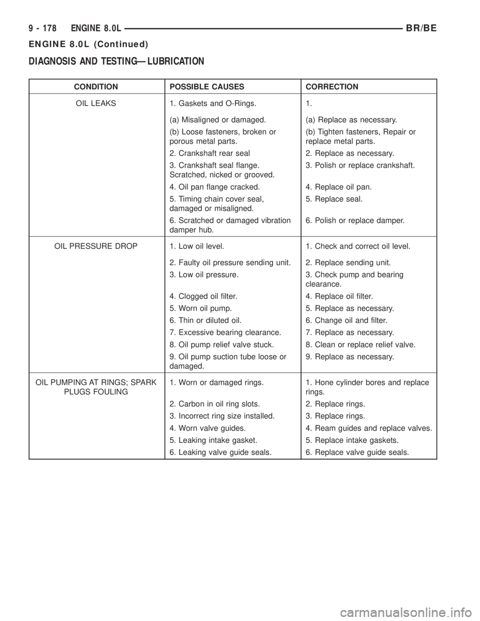
DIAGNOSIS AND TESTINGÐLUBRICATION
CONDITION POSSIBLE CAUSES CORRECTION
OIL LEAKS 1. Gaskets and O-Rings. 1.
(a) Misaligned or damaged. (a) Replace as necessary.
(b) Loose fasteners, broken or
porous metal parts.(b) Tighten fasteners, Repair or
replace metal parts.
2. Crankshaft rear seal 2. Replace as necessary.
3. Crankshaft seal flange.
Scratched, nicked or grooved.3. Polish or replace crankshaft.
4. Oil pan flange cracked. 4. Replace oil pan.
5. Timing chain cover seal,
damaged or misaligned.5. Replace seal.
6. Scratched or damaged vibration
damper hub.6. Polish or replace damper.
OIL PRESSURE DROP 1. Low oil level. 1. Check and correct oil level.
2. Faulty oil pressure sending unit. 2. Replace sending unit.
3. Low oil pressure. 3. Check pump and bearing
clearance.
4. Clogged oil filter. 4. Replace oil filter.
5. Worn oil pump. 5. Replace as necessary.
6. Thin or diluted oil. 6. Change oil and filter.
7. Excessive bearing clearance. 7. Replace as necessary.
8. Oil pump relief valve stuck. 8. Clean or replace relief valve.
9. Oil pump suction tube loose or
damaged.9. Replace as necessary.
OIL PUMPING AT RINGS; SPARK
PLUGS FOULING1. Worn or damaged rings. 1. Hone cylinder bores and replace
rings.
2. Carbon in oil ring slots. 2. Replace rings.
3. Incorrect ring size installed. 3. Replace rings.
4. Worn valve guides. 4. Ream guides and replace valves.
5. Leaking intake gasket. 5. Replace intake gaskets.
6. Leaking valve guide seals. 6. Replace valve guide seals.
9 - 178 ENGINE 8.0LBR/BE
ENGINE 8.0L (Continued)
Page 1328 of 2889
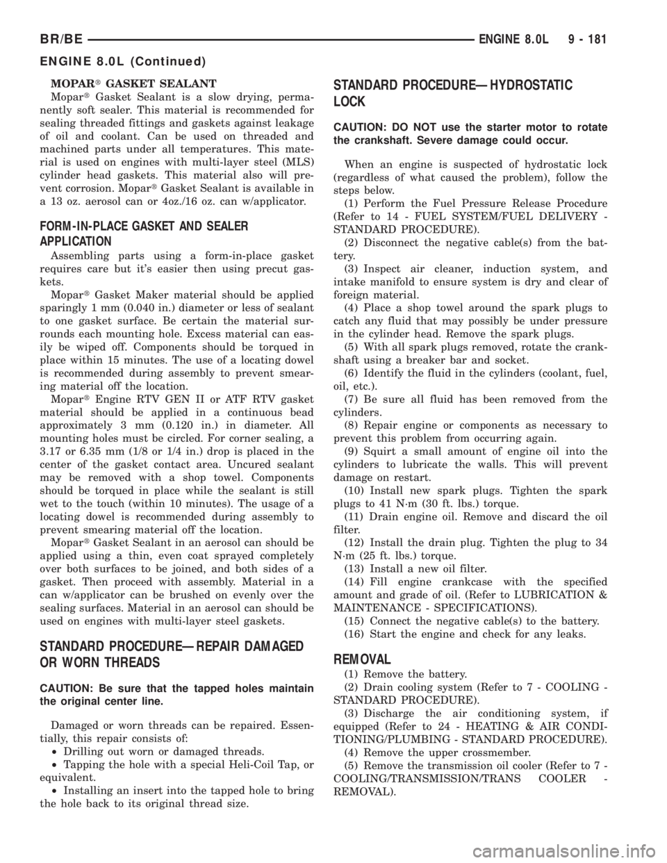
MOPARtGASKET SEALANT
MopartGasket Sealant is a slow drying, perma-
nently soft sealer. This material is recommended for
sealing threaded fittings and gaskets against leakage
of oil and coolant. Can be used on threaded and
machined parts under all temperatures. This mate-
rial is used on engines with multi-layer steel (MLS)
cylinder head gaskets. This material also will pre-
vent corrosion. MopartGasket Sealant is available in
a 13 oz. aerosol can or 4oz./16 oz. can w/applicator.
FORM-IN-PLACE GASKET AND SEALER
APPLICATION
Assembling parts using a form-in-place gasket
requires care but it's easier then using precut gas-
kets.
MopartGasket Maker material should be applied
sparingly 1 mm (0.040 in.) diameter or less of sealant
to one gasket surface. Be certain the material sur-
rounds each mounting hole. Excess material can eas-
ily be wiped off. Components should be torqued in
place within 15 minutes. The use of a locating dowel
is recommended during assembly to prevent smear-
ing material off the location.
MopartEngine RTV GEN II or ATF RTV gasket
material should be applied in a continuous bead
approximately 3 mm (0.120 in.) in diameter. All
mounting holes must be circled. For corner sealing, a
3.17 or 6.35 mm (1/8 or 1/4 in.) drop is placed in the
center of the gasket contact area. Uncured sealant
may be removed with a shop towel. Components
should be torqued in place while the sealant is still
wet to the touch (within 10 minutes). The usage of a
locating dowel is recommended during assembly to
prevent smearing material off the location.
MopartGasket Sealant in an aerosol can should be
applied using a thin, even coat sprayed completely
over both surfaces to be joined, and both sides of a
gasket. Then proceed with assembly. Material in a
can w/applicator can be brushed on evenly over the
sealing surfaces. Material in an aerosol can should be
used on engines with multi-layer steel gaskets.
STANDARD PROCEDUREÐREPAIR DAMAGED
OR WORN THREADS
CAUTION: Be sure that the tapped holes maintain
the original center line.
Damaged or worn threads can be repaired. Essen-
tially, this repair consists of:
²Drilling out worn or damaged threads.
²Tapping the hole with a special Heli-Coil Tap, or
equivalent.
²Installing an insert into the tapped hole to bring
the hole back to its original thread size.
STANDARD PROCEDUREÐHYDROSTATIC
LOCK
CAUTION: DO NOT use the starter motor to rotate
the crankshaft. Severe damage could occur.
When an engine is suspected of hydrostatic lock
(regardless of what caused the problem), follow the
steps below.
(1) Perform the Fuel Pressure Release Procedure
(Refer to 14 - FUEL SYSTEM/FUEL DELIVERY -
STANDARD PROCEDURE).
(2) Disconnect the negative cable(s) from the bat-
tery.
(3) Inspect air cleaner, induction system, and
intake manifold to ensure system is dry and clear of
foreign material.
(4) Place a shop towel around the spark plugs to
catch any fluid that may possibly be under pressure
in the cylinder head. Remove the spark plugs.
(5) With all spark plugs removed, rotate the crank-
shaft using a breaker bar and socket.
(6) Identify the fluid in the cylinders (coolant, fuel,
oil, etc.).
(7) Be sure all fluid has been removed from the
cylinders.
(8) Repair engine or components as necessary to
prevent this problem from occurring again.
(9) Squirt a small amount of engine oil into the
cylinders to lubricate the walls. This will prevent
damage on restart.
(10) Install new spark plugs. Tighten the spark
plugs to 41 N´m (30 ft. lbs.) torque.
(11) Drain engine oil. Remove and discard the oil
filter.
(12) Install the drain plug. Tighten the plug to 34
N´m (25 ft. lbs.) torque.
(13) Install a new oil filter.
(14) Fill engine crankcase with the specified
amount and grade of oil. (Refer to LUBRICATION &
MAINTENANCE - SPECIFICATIONS).
(15) Connect the negative cable(s) to the battery.
(16) Start the engine and check for any leaks.
REMOVAL
(1) Remove the battery.
(2) Drain cooling system (Refer to 7 - COOLING -
STANDARD PROCEDURE).
(3) Discharge the air conditioning system, if
equipped (Refer to 24 - HEATING & AIR CONDI-
TIONING/PLUMBING - STANDARD PROCEDURE).
(4) Remove the upper crossmember.
(5) Remove the transmission oil cooler (Refer to 7 -
COOLING/TRANSMISSION/TRANS COOLER -
REMOVAL).
BR/BEENGINE 8.0L 9 - 181
ENGINE 8.0L (Continued)
Page 1329 of 2889
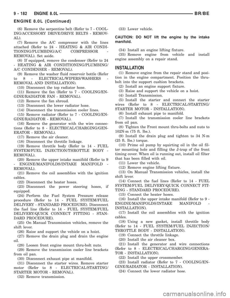
(6) Remove the serpentine belt (Refer to 7 - COOL-
ING/ACCESSORY DRIVE/DRIVE BELTS - REMOV-
AL).
(7) Remove the A/C compressor with the lines
attached (Refer to 24 - HEATING & AIR CONDI-
TIONING/PLUMBING/A/C COMPRESSOR -
REMOVAL). Set aside.
(8) If equipped, remove the condenser (Refer to 24
- HEATING & AIR CONDITIONING/PLUMBING/
A/C CONDENSER - REMOVAL).
(9) Remove the washer fluid reservoir bottle (Refer
to 8 - ELECTRICAL/WIPERS/WASHERS -
REMOVAL AND INSTALLATION).
(10) Disconnect the top radiator hose.
(11) Remove the fan (Refer to 7 - COOLING/EN-
GINE/RADIATOR FAN - REMOVAL).
(12) Remove the fan shroud.
(13) Disconnect the lower radiator hose.
(14) Disconnect the transmission cooler lines.
(15) Remove radiator (Refer to 7 - COOLING/EN-
GINE/RADIATOR - REMOVAL).
(16) Remove the generator with the wire connec-
tions (Refer to 8 - ELECTRICAL/CHARGING/GEN-
ERATOR - REMOVAL).
(17) Remove the air cleaner.
(18) Disconnect the throttle linkage.
(19) Remove throttle body (Refer to 14 - FUEL
SYSTEM/FUEL INJECTION/THROTTLE BODY -
REMOVAL).
(20) Remove the upper intake manifold (Refer to 9
- ENGINE/MANIFOLDS/INTAKE MANIFOLD -
REMOVAL).
(21) Remove the coil assemblies with the ignition
cables.
(22) Disconnect the heater hoses.
(23) Disconnect the power steering hoses, if
equipped.
(24) Perform the Fuel System Pressure release
procedure (Refer to 14 - FUEL SYSTEM/FUEL
DELIVERY - STANDARD PROCEDURE). Disconnect
the fuel line (Refer to 14 - FUEL SYSTEM/FUEL
DELIVERY/QUICK CONNECT FITTING - STAN-
DARD PROCEDURE).
(25) On Manual Transmission vehicles, remove the
shift lever.
(26) Raise and support the vehicle on a hoist.
(27) Remove the drain plug and drain the engine
oil.
(28) Loosen front engine mount thru-bolt nuts.
(29) Remove the transmission cooler line brackets
from oil pan.
(30) Disconnect exhaust pipe at manifold.
(31) Disconnect the starter wires. Remove starter
motor (Refer to 8 - ELECTRICAL/STARTING/
STARTER MOTOR - REMOVAL).
(32) Remove transmission.(33) Lower vehicle.
CAUTION: DO NOT lift the engine by the intake
manifold.
(34) Install an engine lifting fixture.
(35) Remove engine from vehicle and install
engine assembly on a repair stand.
INSTALLATION
(1) Remove engine from the repair stand and posi-
tion in the engine compartment. Position the thru-
bolt into the support cushion brackets.
(2) Install an engine support fixture.
(3) Raise and support the vehicle on a hoist.
(4) Install Transmission.
(5) Install the starter and connect the starter
wires (Refer to 8 - ELECTRICAL/STARTING/
STARTER MOTOR - INSTALLATION).
(6) Install exhaust pipe to manifold.
(7) Install the transmission cooler line brackets
from oil pan.
(8) Tighten the Front mount thru-bolts and nuts to
102N´m (75 ft. lbs.).
(9) Install the drain plug and tighten to 34 N´m
(25 ft. lbs.) torque.
(10) Prime oil pump by squirting oil in the oil fil-
ter mounting hole and filling the J-trap of the front
timing cover. When oil is running out, install oil filter
that has been filled with oil.
(11) Lower the vehicle.
(12) Remove engine lifting fixture.
(13) On Manual Transmission vehicles, install the
shift lever.
(14) Connect the fuel lines (Refer to 14 - FUEL
SYSTEM/FUEL DELIVERY/QUICK CONNECT FIT-
TING - STANDARD PROCEDURE).
(15) Connect the heater hoses.
(16) Install the upper intake manifold (Refer to 9 -
ENGINE/MANIFOLDS/INTAKE MANIFOLD -
INSTALLATION).
(17) Install the coil assemblies with the ignition
cables.
(18) Using a new gasket, install throttle body
(Refer to 14 - FUEL SYSTEM/FUEL INJECTION/
THROTTLE BODY - INSTALLATION).
(19) Connect the throttle linkage.
(20) Install the air cleaner box.
(21) Install the generator and wire connections
(Refer to 8 - ELECTRICAL/CHARGING/GENERA-
TOR - INSTALLATION).
(22) Install the upper crossmember.
(23) Install radiator (Refer to 7 - COOLING/EN-
GINE/RADIATOR - INSTALLATION).
(24) Connect the lower radiator hose.
9 - 182 ENGINE 8.0LBR/BE
ENGINE 8.0L (Continued)