2001 DODGE RAM oil filter
[x] Cancel search: oil filterPage 464 of 2889

ENGINE CONTROL MODULE
DESCRIPTION - ECM
The ECM is bolted to the left side of the engine
behind the fuel filter (Fig. 14). It is a separate com-
ponent and can be serviced. The FPCM is internal to
the fuel injection pump (Fig. 15) and cannot be ser-
viced.
OPERATION - ECM
The main functions of the Engine Control Module
(ECM) and Fuel Injection Pump Control Module
(FPCM) are to electrically control the fuel system.
The Powertrain Control Module (PCM)does not
controlthe fuel system.
The ECM can adapt its programming to meet
changing operating conditions.If the ECM has
been replaced, flashed or re-calibrated, the
ECM must learn the Accelerator Pedal Position
Sensor (APPS) idle voltage. Failure to learn
this voltage may result in unnecessary diagnos-
tic trouble codes. Refer to ECM Removal/Instal-
lation for learning procedures.
The ECM receives input signals from various
switches and sensors. Based on these inputs, the
ECM regulates various engine and vehicle operations
through different system components. These compo-
nents are referred to asECM Outputs.The sensors
and switches that provide inputs to the ECM are
consideredECM Inputs.NOTE: ECM Inputs:
²Accelerator Pedal Position Sensor (APPS) Volts
²APPS Idle Validation Switches #1 and #2
²Battery voltage
²Camshaft Position Sensor (CMP)
²CCD bus (+) circuits
²CCD bus (-) circuits
²Crankshaft Position Sensor (CKP)
²Data link connection for DRB scan tool
²(FPCM) Fuel Injection Pump Control Module
²Engine Coolant Temperature (ECT) sensor
²Ground circuits
²Intake manifold Air Temperature (IAT) sensor
²Manifold Air Pressure Sensor (Boost Pressure
Sensor)
²Oil pressure sensor
²PCM
²Power Take Off (PTO)
²Power ground
²Sensor return
²Signal ground
²Water-In-Fuel (WIF) sensor
Fig. 14 Engine Control Module (ECM) Location
1 - ENGINE CONTROL MODULE (ECM)
2 - HEX HEADED BOLT
3 - 50-WAY CONNECTOR
4 - FUEL TRANSFER PUMP
5 - MOUNTING BOLTS (3)
Fig. 15 Fuel Injection Pump Control Module (FPCM)
Location
1 - FPCM ELECTRICAL CONNECTOR
2 - HIGH-PRESSURE FUEL LINES
3 - FITTINGS
4 - FUEL INJECTION PUMP
5 - FPCM
BR/BEELECTRONIC CONTROL MODULES 8E - 13
Page 465 of 2889

NOTE: ECM Outputs:
After inputs are received by the ECM, certain sen-
sors, switches and components are controlled or reg-
ulated by the ECM. These are consideredECM
Outputs.These outputs are for:
²CCD bus (+) circuits
²CCD bus (-) circuits
²CKP and APPS outputs to the PCM
²Data link connection for DRB scan tool
²Five volt sensor supply
²Fuel injection pump
²Fuel injection pump relay
²(FPCM) Fuel Pump Control Module
²Fuel transfer (lift) pump
²Intake manifold air heater relays #1 and #2 con-
trol circuits
²Malfunction indicator lamp (Check engine lamp)
²Oil pressure gauge/warning lamp
²PCM
²Wait-to-start warning lamp
²Water-In-Fuel (WIF) warning lamp
REMOVAL
The ECM is bolted to the engine block behind the
fuel filter (Fig. 16).
(1) Record any Diagnostic Trouble Codes (DTC's)
found in the PCM or ECM.To avoid possible voltage spike damage to either
the Powertrain Control Module (PCM) or ECM, igni-
tion key must be off, and negative battery cables
must be disconnected before unplugging ECM con-
nectors.
(2) Disconnect both negative battery cables at both
batteries.
(3) Remove 50±way electrical connector bolt at
ECM (Fig. 16). Note: Connector bolt is female 4mm
hex head. To remove bolt, use a ball-hex bit or ball-
hex screwdriver such as Snap-Ont4mm SDABM4
(5/32º may also be used). As bolt is being removed,
very carefully remove connector from ECM.
(4) Remove three ECM mounting bolts and remove
ECM from vehicle.
INSTALLATION
Do not apply paint to back of ECM. Poor ground
will result.
(1) Clean ECM mounting points at engine block.
(2) Position ECM to engine block and install 3
mounting bolts. Tighten bolts to 24 N´m (18 ft. lbs.).
(3) Check pin connectors in ECM and 50±way con-
nector for corrosion or damage. Repair as necessary.
(4) Clean pins in 50±way electrical connector with
a quick-dry electrical contact cleaner.
(5) Very carefully install 50±way connector to
ECM. Tighten connector hex bolt.
(6) Install battery cables.
(7)Turn key to ON position. Without starting
engine, slowly press throttle pedal to floor and
then slowly release. This step must be done
(one time) to ensure accelerator pedal position
sensor calibration has been learned by ECM. If
not done, possible DTC's may be set.
(8) Use DRB scan tool to erase any stored compan-
ion DTC's from PCM.
POWERTRAIN CONTROL
MODULE
DESCRIPTION - PCM
The Powertrain Control Module (PCM) is located
in the engine compartment (Fig. 17). The PCM is
referred to as JTEC.
DESCRIPTION - MODES OF OPERATION
As input signals to the Powertrain Control Module
(PCM) change, the PCM adjusts its response to the
output devices. For example, the PCM must calculate
different injector pulse width and ignition timing for
idle than it does for wide open throttle (WOT).
The PCM will operate in two different modes:
Open Loop and Closed Loop.
Fig. 16 Engine Control Module (ECM) Location and
Mounting
1 - ENGINE CONTROL MODULE (ECM)
2 - HEX HEADED BOLT
3 - 50-WAY CONNECTOR
4 - FUEL TRANSFER PUMP
5 - MOUNTING BOLTS (3)
8E - 14 ELECTRONIC CONTROL MODULESBR/BE
ENGINE CONTROL MODULE (Continued)
Page 1094 of 2889
Connector Name/Number Color Location Fig.
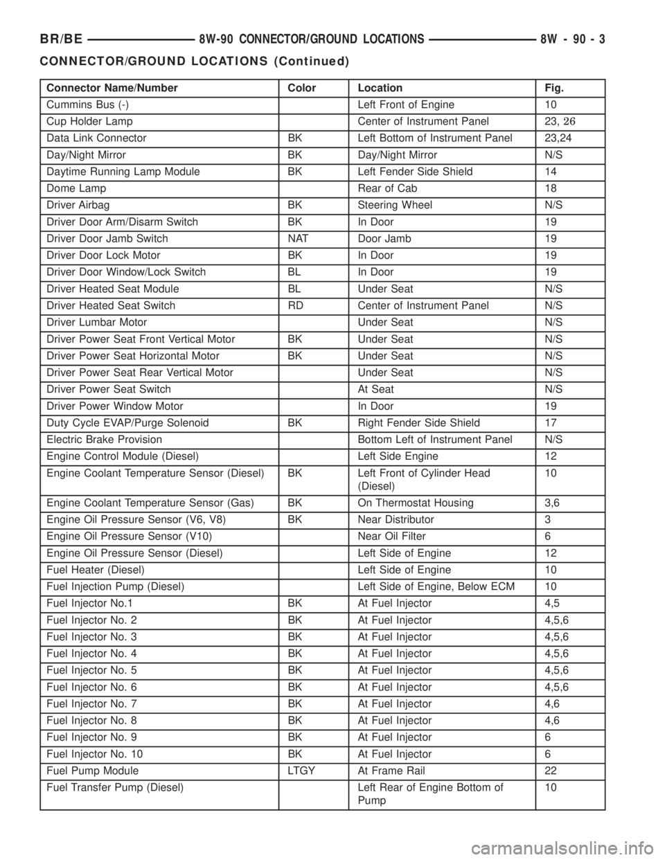
Cummins Bus (-) Left Front of Engine 10
Cup Holder Lamp Center of Instrument Panel 23,26
Data Link Connector BK Left Bottom of Instrument Panel 23,24
Day/Night Mirror BK Day/Night Mirror N/S
Daytime Running Lamp Module BK Left Fender Side Shield 14
Dome Lamp Rear of Cab 18
Driver Airbag BK Steering Wheel N/S
Driver Door Arm/Disarm Switch BK In Door 19
Driver Door Jamb Switch NAT Door Jamb 19
Driver Door Lock Motor BK In Door 19
Driver Door Window/Lock Switch BL In Door 19
Driver Heated Seat Module BL Under Seat N/S
Driver Heated Seat Switch RD Center of Instrument Panel N/S
Driver Lumbar Motor Under Seat N/S
Driver Power Seat Front Vertical Motor BK Under Seat N/S
Driver Power Seat Horizontal Motor BK Under Seat N/S
Driver Power Seat Rear Vertical Motor Under Seat N/S
Driver Power Seat Switch At Seat N/S
Driver Power Window Motor In Door 19
Duty Cycle EVAP/Purge Solenoid BK Right Fender Side Shield 17
Electric Brake Provision Bottom Left of Instrument Panel N/S
Engine Control Module (Diesel) Left Side Engine 12
Engine Coolant Temperature Sensor (Diesel) BK Left Front of Cylinder Head
(Diesel)10
Engine Coolant Temperature Sensor (Gas) BK On Thermostat Housing 3,6
Engine Oil Pressure Sensor (V6, V8) BK Near Distributor 3
Engine Oil Pressure Sensor (V10) Near Oil Filter 6
Engine Oil Pressure Sensor (Diesel) Left Side of Engine 12
Fuel Heater (Diesel) Left Side of Engine 10
Fuel Injection Pump (Diesel) Left Side of Engine, Below ECM 10
Fuel Injector No.1 BK At Fuel Injector 4,5
Fuel Injector No. 2 BK At Fuel Injector 4,5,6
Fuel Injector No. 3 BK At Fuel Injector 4,5,6
Fuel Injector No. 4 BK At Fuel Injector 4,5,6
Fuel Injector No. 5 BK At Fuel Injector 4,5,6
Fuel Injector No. 6 BK At Fuel Injector 4,5,6
Fuel Injector No. 7 BK At Fuel Injector 4,6
Fuel Injector No. 8 BK At Fuel Injector 4,6
Fuel Injector No. 9 BK At Fuel Injector 6
Fuel Injector No. 10 BK At Fuel Injector 6
Fuel Pump Module LTGY At Frame Rail 22
Fuel Transfer Pump (Diesel) Left Rear of Engine Bottom of
Pump10
BR/BE8W-90 CONNECTOR/GROUND LOCATIONS 8W - 90 - 3
CONNECTOR/GROUND LOCATIONS (Continued)
Page 1149 of 2889
INSTALLATION...........................34
CRANKSHAFT OIL SEAL - REAR
DESCRIPTION...........................34
OPERATION.............................34
REMOVAL..............................35
INSTALLATION...........................35
DISTRIBUTOR BUSHING
REMOVAL..............................37
INSTALLATION...........................37
HYDRAULIC LIFTERS (CAM IN BLOCK)
DIAGNOSIS AND TESTING.................38
HYDRAULIC TAPPETS...................38
REMOVAL..............................39
CLEANING..............................39
INSTALLATION...........................39
PISTON & CONNECTING ROD
DESCRIPTION...........................40
STANDARD PROCEDURE..................40
PISTON FITTING.......................40
REMOVAL..............................40
CLEANING..............................41
INSPECTION............................41
INSTALLATION...........................41
PISTON RINGS
STANDARD PROCEDURE..................41
PISTON RING FITTING..................41
VIBRATION DAMPER
REMOVAL..............................42
INSTALLATION...........................42
FRONT MOUNT
REMOVAL..............................43
INSTALLATION...........................43
REAR MOUNT
REMOVAL..............................44
INSTALLATION...........................44
LUBRICATION
DESCRIPTION...........................45
OPERATION.............................45
DIAGNOSIS AND TESTING.................47
ENGINE OIL PRESSURE.................47
ENGINE OIL LEAKS.....................47
OIL
STANDARD PROCEDURE..................47
ENGINE OIL...........................47OIL FILTER
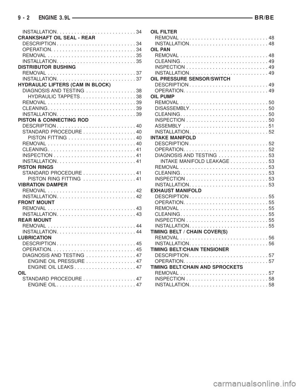
REMOVAL..............................48
INSTALLATION...........................48
OIL PAN
REMOVAL..............................48
CLEANING..............................49
INSPECTION............................49
INSTALLATION...........................49
OIL PRESSURE SENSOR/SWITCH
DESCRIPTION...........................49
OPERATION.............................49
OIL PUMP
REMOVAL..............................50
DISASSEMBLY...........................50
CLEANING..............................50
INSPECTION............................50
ASSEMBLY.............................51
INSTALLATION...........................52
INTAKE MANIFOLD
DESCRIPTION...........................52
OPERATION.............................52
DIAGNOSIS AND TESTING.................53
INTAKE MANIFOLD LEAKAGE.............53
REMOVAL..............................53
CLEANING..............................53
INSPECTION............................53
INSTALLATION...........................53
EXHAUST MANIFOLD
DESCRIPTION...........................55
OPERATION.............................55
REMOVAL..............................55
CLEANING..............................55
INSPECTION............................55
INSTALLATION...........................55
TIMING BELT / CHAIN COVER(S)
REMOVAL..............................56
INSTALLATION...........................56
TIMING BELT/CHAIN TENSIONER
DESCRIPTION...........................57
OPERATION.............................57
TIMING BELT/CHAIN AND SPROCKETS
REMOVAL..............................57
INSPECTION............................58
INSTALLATION...........................58
9 - 2 ENGINE 3.9LBR/BE
Page 1150 of 2889
ENGINE 3.9L
DESCRIPTION
The 3.9 Liter (238 CID) six-cylinder engine is a
V-Type, lightweight, single cam, overhead valve
engine with hydraulic roller tappets. This engine is
designed to use unleaded fuel.
The engine lubrication system consists of a rotor
type oil pump and a full-flow oil filter.
The cylinders are numbered from front to rear; 1,
3, 5 on the left bank and 2, 4, 6 on the right bank.
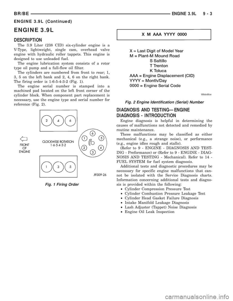
The firing order is 1-6-5-4-3-2 (Fig. 1).
The engine serial number is stamped into a
machined pad located on the left front corner of the
cylinder block. When component part replacement is
necessary, use the engine type and serial number for
reference (Fig. 2).
DIAGNOSIS AND TESTINGÐENGINE
DIAGNOSIS - INTRODUCTION
Engine diagnosis is helpful in determining the
causes of malfunctions not detected and remedied by
routine maintenance.
These malfunctions may be classified as either
mechanical (e.g., a strange noise), or performance
(e.g., engine idles rough and stalls).
(Refer to 9 - ENGINE - DIAGNOSIS AND TEST-
ING - Preformance) or (Refer to 9 - ENGINE - DIAG-
NOSIS AND TESTING - Mechanical). Refer to 14 -
FUEL SYSTEM for fuel system diagnosis.
Additional tests and diagnostic procedures may be
necessary for specific engine malfunctions that can-
not be isolated with the Service Diagnosis charts.
Information concerning additional tests and diagno-
sis is provided within the following:
²Cylinder Compression Pressure Test
²Cylinder Combustion Pressure Leakage Test
²Cylinder Head Gasket Failure Diagnosis
²Intake Manifold Leakage Diagnosis
²Lash Adjuster (Tappet) Noise Diagnosis
²Engine Oil Leak Inspection
Fig. 1 Firing Order
Fig. 2 Engine Identification (Serial) Number
BR/BEENGINE 3.9L 9 - 3
ENGINE 3.9L (Continued)
Page 1154 of 2889
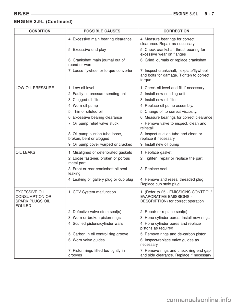
CONDITION POSSIBLE CAUSES CORRECTION
4. Excessive main bearing clearance 4. Measure bearings for correct
clearance. Repair as necessary
5. Excessive end play 5. Check crankshaft thrust bearing for
excessive wear on flanges
6. Crankshaft main journal out of
round or worn6. Grind journals or replace crankshaft
7. Loose flywheel or torque converter 7. Inspect crankshaft, flexplate/flywheel
and bolts for damage. Tighten to correct
torque
LOW OIL PRESSURE 1. Low oil level 1. Check oil level and fill if necessary
2. Faulty oil pressure sending unit 2. Install new sending unit
3. Clogged oil filter 3. Install new oil filter
4. Worn oil pump 4. Replace oil pump assembly.
5. Thin or diluted oil 5. Change oil to correct viscosity.
6. Excessive bearing clearance 6. Measure bearings for correct clearance
7. Oil pump relief valve stuck 7. Remove valve to inspect, clean and
reinstall
8. Oil pump suction tube loose,
broken, bent or clogged8. Inspect suction tube and clean or
replace if necessary
9. Oil pump cover warped or cracked 9. Install new oil pump
OIL LEAKS 1. Misaligned or deteriorated gaskets 1. Replace gasket
2. Loose fastener, broken or porous
metal part2. Tighten, repair or replace the part
3. Front or rear crankshaft oil seal
leaking3. Replace seal
4. Leaking oil gallery plug or cup plug 4. Remove and reseal threaded plug.
Replace cup style plug
EXCESSIVE OIL
CONSUMPTION OR
SPARK PLUGS OIL
FOULED1. CCV System malfunction 1. (Refer to 25 - EMISSIONS CONTROL/
EVAPORATIVE EMISSIONS -
DESCRIPTION) for correct operation
2. Defective valve stem seal(s) 2. Repair or replace seal(s)
3. Worn or broken piston rings 3. Hone cylinder bores. Install new rings
4. Scuffed pistons/cylinder walls 4. Hone cylinder bores and replace
pistons as required
5. Carbon in oil control ring groove 5. Remove rings and de-carbon piston
6. Worn valve guides 6. Inspect/replace valve guides as
necessary
7. Piston rings fitted too tightly in
grooves7. Remove rings and check ring end gap
and side clearance. Replace if necessary
BR/BEENGINE 3.9L 9 - 7
ENGINE 3.9L (Continued)
Page 1155 of 2889
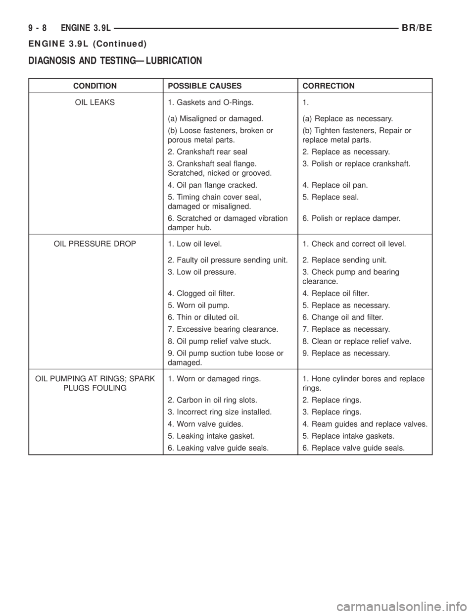
DIAGNOSIS AND TESTINGÐLUBRICATION
CONDITION POSSIBLE CAUSES CORRECTION
OIL LEAKS 1. Gaskets and O-Rings. 1.
(a) Misaligned or damaged. (a) Replace as necessary.
(b) Loose fasteners, broken or
porous metal parts.(b) Tighten fasteners, Repair or
replace metal parts.
2. Crankshaft rear seal 2. Replace as necessary.
3. Crankshaft seal flange.
Scratched, nicked or grooved.3. Polish or replace crankshaft.
4. Oil pan flange cracked. 4. Replace oil pan.
5. Timing chain cover seal,
damaged or misaligned.5. Replace seal.
6. Scratched or damaged vibration
damper hub.6. Polish or replace damper.
OIL PRESSURE DROP 1. Low oil level. 1. Check and correct oil level.
2. Faulty oil pressure sending unit. 2. Replace sending unit.
3. Low oil pressure. 3. Check pump and bearing
clearance.
4. Clogged oil filter. 4. Replace oil filter.
5. Worn oil pump. 5. Replace as necessary.
6. Thin or diluted oil. 6. Change oil and filter.
7. Excessive bearing clearance. 7. Replace as necessary.
8. Oil pump relief valve stuck. 8. Clean or replace relief valve.
9. Oil pump suction tube loose or
damaged.9. Replace as necessary.
OIL PUMPING AT RINGS; SPARK
PLUGS FOULING1. Worn or damaged rings. 1. Hone cylinder bores and replace
rings.
2. Carbon in oil ring slots. 2. Replace rings.
3. Incorrect ring size installed. 3. Replace rings.
4. Worn valve guides. 4. Ream guides and replace valves.
5. Leaking intake gasket. 5. Replace intake gaskets.
6. Leaking valve guide seals. 6. Replace valve guide seals.
9 - 8 ENGINE 3.9LBR/BE
ENGINE 3.9L (Continued)
Page 1157 of 2889
DIAGNOSIS AND TESTINGÐREAR SEAL AREA
LEAKS
Since it is sometimes difficult to determine the
source of an oil leak in the rear seal area of the
engine, a more involved inspection is necessary. The
following steps should be followed to help pinpoint
the source of the leak.
If the leakage occurs at the crankshaft rear oil seal
area:
(1) Disconnect the battery.
(2) Raise the vehicle.
(3) Remove torque converter or clutch housing
cover and inspect rear of block for evidence of oil.
Use a black light to check for the oil leak:
(a) Circular spray pattern generally indicates
seal leakage or crankshaft damage.
(b) Where leakage tends to run straight down,
possible causes are a porous block, distributor seal,
camshaft bore cup plugs, oil galley pipe plugs, oil
filter runoff, and main bearing cap to cylinder
block mating surfaces.
(4) If no leaks are detected, pressurized the crank-
case as outlined in (Refer to 9 - ENGINE/LUBRICA-
TION - DIAGNOSIS AND TESTING)
CAUTION: Do not exceed 20.6 kPa (3 psi).
(5) If the leak is not detected, very slowly turn the
crankshaft and watch for leakage. If a leak is
detected between the crankshaft and seal while
slowly turning the crankshaft, it is possible the
crankshaft seal surface is damaged. The seal area on
the crankshaft could have minor nicks or scratches
that can be polished out with emery cloth.
CAUTION: Use extreme caution when crankshaft
polishing is necessary to remove minor nicks or
scratches. The crankshaft seal flange is specially
machined to complement the function of the rear oil
seal.
(6) For bubbles that remain steady with shaft
rotation, no further inspection can be done until dis-
assembled. Refer to the service DiagnosisÐMechani-
cal, under the Oil Leak row, for components
inspections on possible causes and corrections.
(7) After the oil leak root cause and appropriate
corrective action have been identified, (Refer to 9 -
ENGINE/ENGINE BLOCK/CRANKSHAFT OIL
SEAL - REAR - REMOVAL), for proper replacement
procedures.
STANDARD PROCEDUREÐCYLINDER BORE
HONING
Before honing, stuff plenty of clean shop towels
under the bores and over the crankshaft to keep
abrasive materials from entering the crankshaft
area.
(1) Used carefully, the Cylinder Bore Sizing Hone
C-823, equipped with 220 grit stones, is the best tool
for this job. In addition to deglazing, it will reduce
taper and out-of-round, as well as removing light
scuffing, scoring and scratches. Usually, a few strokes
will clean up a bore and maintain the required lim-
its.
CAUTION: DO NOT use rigid type hones to remove
cylinder wall glaze.
(2) Deglazing of the cylinder walls may be done if
the cylinder bore is straight and round. Use a cylin-
der surfacing hone, Honing Tool C-3501, equipped
with 280 grit stones (C-3501-3810). about 20-60
strokes, depending on the bore condition, will be suf-
ficient to provide a satisfactory surface. Using honing
oil C-3501-3880, or a light honing oil, available from
major oil distributors.
CAUTION: DO NOT use engine or transmission oil,
mineral spirits, or kerosene.
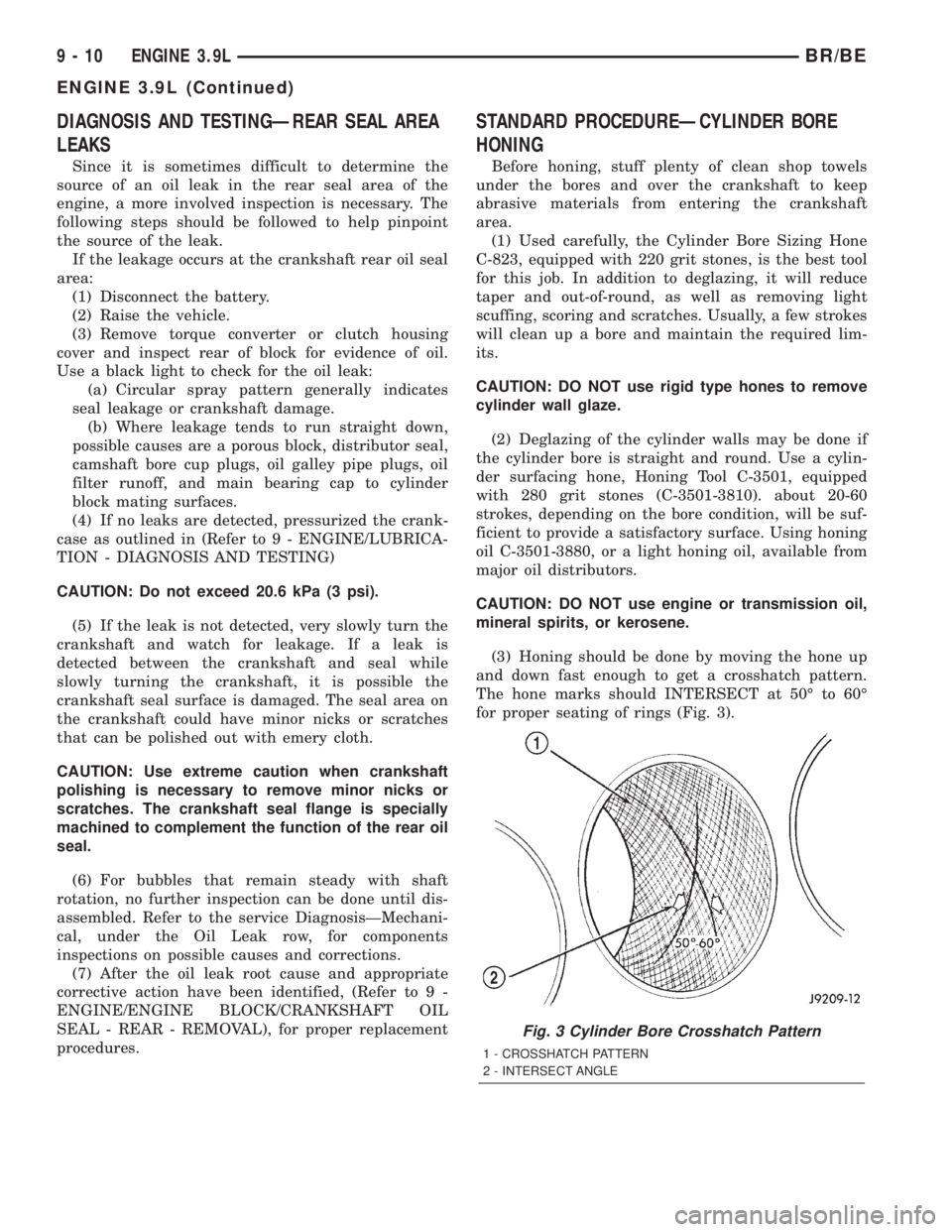
(3) Honing should be done by moving the hone up
and down fast enough to get a crosshatch pattern.
The hone marks should INTERSECT at 50É to 60É
for proper seating of rings (Fig. 3).
Fig. 3 Cylinder Bore Crosshatch Pattern
1 - CROSSHATCH PATTERN
2 - INTERSECT ANGLE
9 - 10 ENGINE 3.9LBR/BE
ENGINE 3.9L (Continued)