2001 DODGE RAM weight
[x] Cancel search: weightPage 1150 of 2889
ENGINE 3.9L
DESCRIPTION
The 3.9 Liter (238 CID) six-cylinder engine is a
V-Type, lightweight, single cam, overhead valve
engine with hydraulic roller tappets. This engine is
designed to use unleaded fuel.
The engine lubrication system consists of a rotor
type oil pump and a full-flow oil filter.
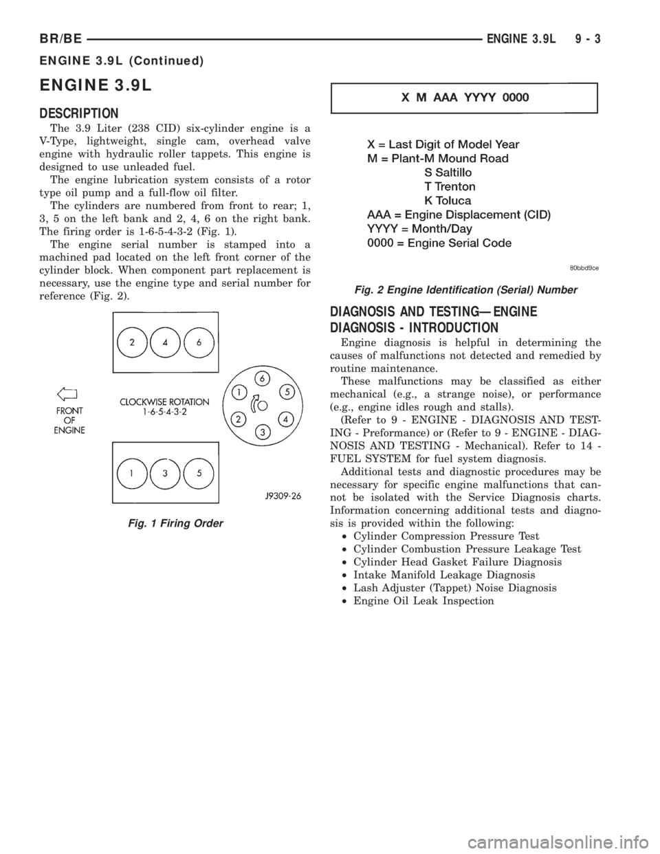
The cylinders are numbered from front to rear; 1,
3, 5 on the left bank and 2, 4, 6 on the right bank.
The firing order is 1-6-5-4-3-2 (Fig. 1).
The engine serial number is stamped into a
machined pad located on the left front corner of the
cylinder block. When component part replacement is
necessary, use the engine type and serial number for
reference (Fig. 2).
DIAGNOSIS AND TESTINGÐENGINE
DIAGNOSIS - INTRODUCTION
Engine diagnosis is helpful in determining the
causes of malfunctions not detected and remedied by
routine maintenance.
These malfunctions may be classified as either
mechanical (e.g., a strange noise), or performance
(e.g., engine idles rough and stalls).
(Refer to 9 - ENGINE - DIAGNOSIS AND TEST-
ING - Preformance) or (Refer to 9 - ENGINE - DIAG-
NOSIS AND TESTING - Mechanical). Refer to 14 -
FUEL SYSTEM for fuel system diagnosis.
Additional tests and diagnostic procedures may be
necessary for specific engine malfunctions that can-
not be isolated with the Service Diagnosis charts.
Information concerning additional tests and diagno-
sis is provided within the following:
²Cylinder Compression Pressure Test
²Cylinder Combustion Pressure Leakage Test
²Cylinder Head Gasket Failure Diagnosis
²Intake Manifold Leakage Diagnosis
²Lash Adjuster (Tappet) Noise Diagnosis
²Engine Oil Leak Inspection
Fig. 1 Firing Order
Fig. 2 Engine Identification (Serial) Number
BR/BEENGINE 3.9L 9 - 3
ENGINE 3.9L (Continued)
Page 1161 of 2889
SPECIFICATIONS
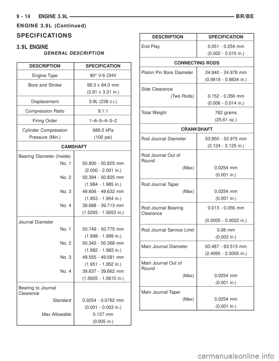
3.9L ENGINE
GENERAL DESCRIPTION
DESCRIPTION SPECIFICATION
Engine Type 90É V-6 OHV
Bore and Stroke 99.3 x 84.0 mm
(3.91 x 3.31 in.)
Displacement 3.9L (238 c.i.)
Compression Ratio 9.1:1
Firing Order 1±6±5±4±3±2
Cylinder Compression 689.5 kPa
Pressure (Min.) (100 psi)
CAMSHAFT
Bearing Diameter (Inside)
No. 1 50.800 - 50.825 mm
(2.000 - 2.001 in.)
No. 2 50.394 - 50.825 mm
(1.984 - 1.985 in.)
No. 3 49.606 - 49.632 mm
(1.953 - 1.954 in.)
No. 4 39.688 - 39.713 mm
(1.5265 - 1.5653 in.)
Journal Diameter
No. 1 50.749 - 50.775 mm
(1.998 - 1.999 in.)
No. 2 50.343 - 50.368 mm
(1.982 - 1.983 in.)
No. 3 49.555 - 49.581 mm
(1.951 - 1.952 in.)
No. 4 39.637 - 39.662 mm
(1.5605 - 1.5615 in.)
Bearing to Journal
Clearance
Standard 0.0254 - 0.0762 mm
(0.001 - 0.003 in.)
Max Allowable 0.127 mm
(0.005 in.)
DESCRIPTION SPECIFICATION
End Play 0.051 - 0.254 mm
(0.002 - 0.010 in.)
CONNECTING RODS
Piston Pin Bore Diameter 24.940 - 24.978 mm
(0.9819 - 0.9834 in.)
Side Clearance
(Two Rods) 0.152 - 0.356 mm
(0.006 - 0.014 in.)
Total Weight 762 grams
(25.61 oz.)
CRANKSHAFT
Rod Journal Diameter 53.950 - 53.975 mm
(2.124 - 2.125 in.)
Rod Journal Out of
Round
(Max) 0.0254 mm
(0.001 in.)
Rod Journal Taper
(Max) 0.0254 mm
(0.001 in.)
Rod Journal Bearing
Clearance0.013 - 0.056 mm
(0.0005 - 0.0022 in.)
Rod Journal Service Limit 0.08 mm
(0.003 in.)
Main Journal Diameter 63.487 - 63.513 mm
(2.4995 - 2.5005 in.)
Main Journal Out of
Round
(Max) 0.0254 mm
(0.001 in.)
Main Journal Taper
(Max) 0.0254 mm
(0.001 in.)
9 - 14 ENGINE 3.9LBR/BE
ENGINE 3.9L (Continued)
Page 1163 of 2889
DESCRIPTION SPECIFICATION
Number of Coils 6.8
Installed Height 41.66 mm
(1.64 in.)
Wire Diameter 4.50 mm
(0.177 in.)
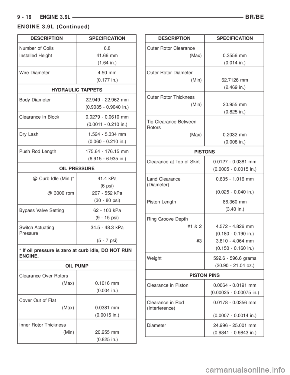
HYDRAULIC TAPPETS
Body Diameter 22.949 - 22.962 mm
(0.9035 - 0.9040 in.)
Clearance in Block 0.0279 - 0.0610 mm
(0.0011 - 0.210 in.)
Dry Lash 1.524 - 5.334 mm
(0.060 - 0.210 in.)
Push Rod Length 175.64 - 176.15 mm
(6.915 - 6.935 in.)
OIL PRESSURE
@ Curb Idle (Min.)* 41.4 kPa
(6 psi)
@ 3000 rpm 207 - 552 kPa
(30 - 80 psi)
Bypass Valve Setting 62 - 103 kPa
(9 - 15 psi)
Switch Actuating
Pressure34.5 - 48.3 kPa
(5 - 7 psi)
* If oil pressure is zero at curb idle, DO NOT RUN
ENGINE.
OIL PUMP
Clearance Over Rotors
(Max) 0.1016 mm
(0.004 in.)
Cover Out of Flat
(Max) 0.0381 mm
(0.0015 in.)
Inner Rotor Thickness
(Min) 20.955 mm
(0.825 in.)DESCRIPTION SPECIFICATION
Outer Rotor Clearance
(Max) 0.3556 mm
(0.014 in.)
Outer Rotor Diameter
(Min) 62.7126 mm
(2.469 in.)
Outer Rotor Thickness
(Min) 20.955 mm
(0.825 in.)
Tip Clearance Between
Rotors
(Max) 0.2032 mm
(0.008 in.)
PISTONS
Clearance at Top of Skirt 0.0127 - 0.0381 mm
(0.0005 - 0.0015 in.)
Land Clearance
(Diameter)0.635 - 1.016 mm
(0.025 - 0.040 in.)
Piston Length 86.360 mm
(3.40 in.)
Ring Groove Depth
#1 & 2 4.572 - 4.826 mm
(0.180 - 0.190 in.)
#3 3.810 - 4.064 mm
(0.150 - 0.160 in.)
Weight 592.6 - 596.6 grams
(20.90 - 21.04 oz.)
PISTON PINS
Clearance in Piston 0.0064 - 0.0191 mm
(0.00025 - 0.00075 in.)
Clearance in Rod
(Interference)0.0178 - 0.0356 mm
(0.0007 - 0.0014 in.)
Diameter 24.996 - 25.001 mm
(0.9841 - 0.9843 in.)
9 - 16 ENGINE 3.9LBR/BE
ENGINE 3.9L (Continued)
Page 1164 of 2889
DESCRIPTION SPECIFICATION
End Play None
Length 75.946 - 76.454 mm
(2.990 - 3.010 in.)
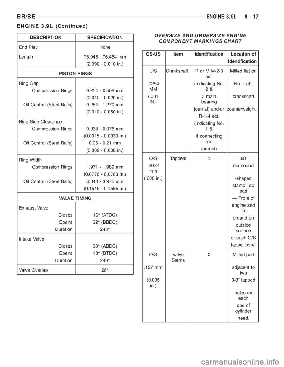
PISTON RINGS
Ring Gap
Compression Rings 0.254 - 0.508 mm
(0.010 - 0.020 in.)
Oil Control (Steel Rails) 0.254 - 1.270 mm
(0.010 - 0.050 in.)
Ring Side Clearance
Compression Rings 0.038 - 0.076 mm
(0.0015 - 0.0030 in.)
Oil Control (Steel Rails) 0.06 - 0.21 mm
(0.002 - 0.008 in.)
Ring Width
Compression Rings 1.971 - 1.989 mm
(0.0776 - 0.0783 in.)
Oil Control (Steel Rails) 3.848 - 3.975 mm
(0.1515 - 0.1565 in.)
VALVE TIMING
Exhaust Valve
Closes 16É (ATDC)
Opens 52É (BBDC)
Duration 248É
Intake Valve
Closes 50É (ABDC)
Opens 10É (BTDC)
Duration 240É
Valve Overlap 26ÉOVERSIZE AND UNDERSIZE ENGINE
COMPONENT MARKINGS CHART
OS-US Item Identification Location of
Identification
U/S Crankshaft R or M M-2-3
ect.Milled flat on
.0254
MM(indicating No.
2&No. eight
(.001
IN.)3 main
bearingcrankshaft
journal) and/or counterweight.
R-1-4 ect.
(indicating No.
1&
4 connecting
rod
journal)
O/S TappetsL3/89
.2032
mmdiamound
(.008 in.) -shaped
stamp Top
pad
Ð Front of
engine and
flat
ground on
outside
surface
of each O/S
tappet bore.
O/S Valve
StemsX Milled pad
.127 mm adjacent to
two
(0.005
in.)3/89tapped
holes on
each
end of
cylinder
head.
BR/BEENGINE 3.9L 9 - 17
ENGINE 3.9L (Continued)
Page 1185 of 2889
HYDRAULIC LIFTERS (CAM IN
BLOCK)
DIAGNOSIS AND TESTINGÐHYDRAULIC
TAPPETS
Before disassembling any part of the engine to cor-
rect tappet noise, check the oil pressure. If vehicle
has no oil pressure gauge, install a reliable gauge at
the pressure sending-unit. The pressure should be
between 207-552 kPa (30-80 psi) at 3,000 RPM.
Check the oil level after the engine reaches normal
operating temperature. Allow 5 minutes to stabilize
oil level, check dipstick. The oil level in the pan
should never be above the FULL mark or below the
ADD OIL mark on dipstick. Either of these two con-
ditions could be responsible for noisy tappets.
OIL LEVEL
HIGH
If oil level is above the FULL mark, it is possible
for the connecting rods to dip into the oil. With the
engine running, this condition could create foam in
the oil pan. Foam in oil pan would be fed to the
hydraulic tappets by the oil pump causing them to
lose length and allow valves to seat noisily.
LOW
Low oil level may allow oil pump to take in air.
When air is fed to the tappets, they lose length,
which allows valves to seat noisily. Any leaks on
intake side of oil pump through which air can be
drawn will create the same tappet action. Check the
lubrication system from the intake strainer to the
pump cover, including the relief valve retainer cap.
When tappet noise is due to aeration, it may be
intermittent or constant, and usually more than one
tappet will be noisy. When oil level and leaks have
been corrected, operate the engine at fast idle. Run
engine for a sufficient time to allow all of the air
inside the tappets to be bled out.
TAPPET NOISE DIAGNOSIS
(1) To determine source of tappet noise, operate
engine at idle with cylinder head covers removed.
(2) Feel each valve spring or rocker arm to detect
noisy tappet. The noisy tappet will cause the affected
spring and/or rocker arm to vibrate or feel rough in
operation.
NOTE: Worn valve guides or cocked springs are
sometimes mistaken for noisy tappets. If such is
the case, noise may be dampened by applying side
thrust on the valve spring. If noise is not apprecia-
bly reduced, it can be assumed the noise is in thetappet. Inspect the rocker arm push rod sockets
and push rod ends for wear.
(3) Valve tappet noise ranges from light noise to a
heavy click. A light noise is usually caused by exces-
sive leak-down around the unit plunger, or by the
plunger partially sticking in the tappet body cylinder.
The tappet should be replaced. A heavy click is
caused by a tappet check valve not seating, or by for-
eign particles wedged between the plunger and the
tappet body. This will cause the plunger to stick in
the down position. This heavy click will be accompa-
nied by excessive clearance between the valve stem
and rocker arm as valve closes. In either case, tappet
assembly should be removed for inspection and clean-
ing.
(4) The valve train generates a noise very much
like a light tappet noise during normal operation.
Care must be taken to ensure that tappets are mak-
ing the noise. If more than one tappet seems to be
noisy, it's probably not the tappets.
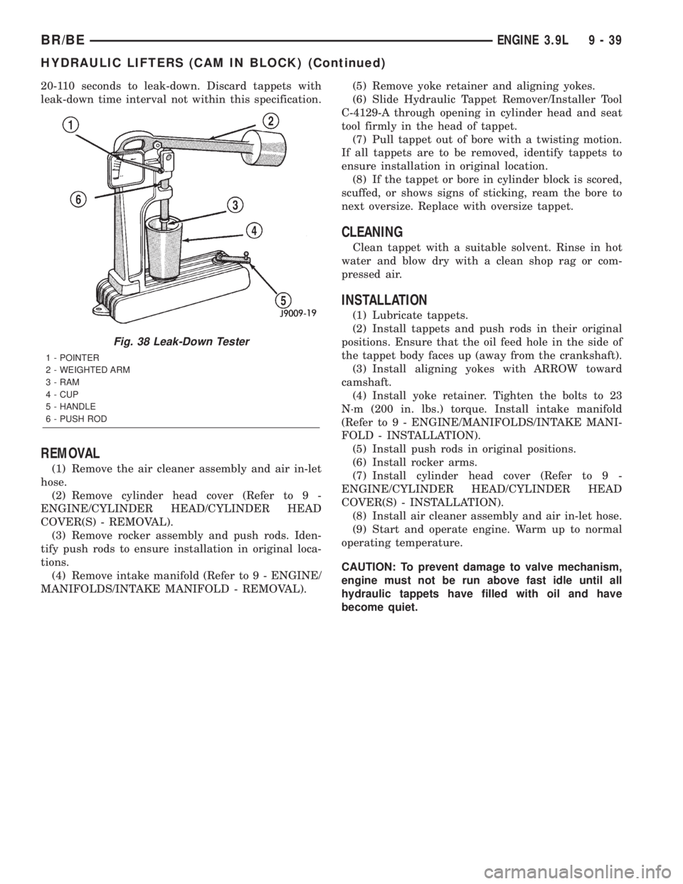
LEAK-DOWN TEST
After cleaning and inspection, test each tappet for
specified leak-down rate tolerance to ensure zero-lash
operation (Fig. 38).
Swing the weighted arm of the hydraulic valve tap-
pet tester away from the ram of the Universal Leak-
Down Tester.
(1) Place a 7.925-7.950 mm (0.312-0.313 inch)
diameter ball bearing on the plunger cap of the tap-
pet.
(2) Lift the ram and position the tappet (with the
ball bearing) inside the tester cup.
(3) Lower the ram, then adjust the nose of the ram
until it contacts the ball bearing. DO NOT tighten
the hex nut on the ram.
(4) Fill the tester cup with hydraulic valve tappet
test oil until the tappet is completely submerged.
(5) Swing the weighted arm onto the push rod and
pump the tappet plunger up and down to remove air.
When the air bubbles cease, swing the weighted arm
away and allow the plunger to rise to the normal
position.
(6) Adjust the nose of the ram to align the pointer
with the SET mark on the scale of the tester and
tighten the hex nut.
(7) Slowly swing the weighted arm onto the push
rod.
(8) Rotate the cup by turning the handle at the
base of the tester clockwise one revolution every 2
seconds.
(9) Observe the leak-down time interval from the
instant the pointer aligns with the START mark on
the scale until the pointer aligns with the 0.125
mark. A normally functioning tappet will require
9 - 38 ENGINE 3.9LBR/BE
Page 1186 of 2889
20-110 seconds to leak-down. Discard tappets with
leak-down time interval not within this specification.
REMOVAL
(1) Remove the air cleaner assembly and air in-let
hose.
(2) Remove cylinder head cover (Refer to 9 -
ENGINE/CYLINDER HEAD/CYLINDER HEAD
COVER(S) - REMOVAL).
(3) Remove rocker assembly and push rods. Iden-
tify push rods to ensure installation in original loca-
tions.
(4) Remove intake manifold (Refer to 9 - ENGINE/
MANIFOLDS/INTAKE MANIFOLD - REMOVAL).(5) Remove yoke retainer and aligning yokes.
(6) Slide Hydraulic Tappet Remover/Installer Tool
C-4129-A through opening in cylinder head and seat
tool firmly in the head of tappet.
(7) Pull tappet out of bore with a twisting motion.
If all tappets are to be removed, identify tappets to
ensure installation in original location.
(8) If the tappet or bore in cylinder block is scored,
scuffed, or shows signs of sticking, ream the bore to
next oversize. Replace with oversize tappet.
CLEANING
Clean tappet with a suitable solvent. Rinse in hot
water and blow dry with a clean shop rag or com-
pressed air.
INSTALLATION
(1) Lubricate tappets.
(2) Install tappets and push rods in their original
positions. Ensure that the oil feed hole in the side of
the tappet body faces up (away from the crankshaft).
(3) Install aligning yokes with ARROW toward
camshaft.
(4) Install yoke retainer. Tighten the bolts to 23
N´m (200 in. lbs.) torque. Install intake manifold
(Refer to 9 - ENGINE/MANIFOLDS/INTAKE MANI-
FOLD - INSTALLATION).
(5) Install push rods in original positions.
(6) Install rocker arms.
(7) Install cylinder head cover (Refer to 9 -
ENGINE/CYLINDER HEAD/CYLINDER HEAD
COVER(S) - INSTALLATION).
(8) Install air cleaner assembly and air in-let hose.
(9) Start and operate engine. Warm up to normal
operating temperature.
CAUTION: To prevent damage to valve mechanism,
engine must not be run above fast idle until all
hydraulic tappets have filled with oil and have
become quiet.
Fig. 38 Leak-Down Tester
1 - POINTER
2 - WEIGHTED ARM
3 - RAM
4 - CUP
5 - HANDLE
6 - PUSH ROD
BR/BEENGINE 3.9L 9 - 39
HYDRAULIC LIFTERS (CAM IN BLOCK) (Continued)
Page 1187 of 2889
PISTON & CONNECTING ROD
DESCRIPTION
The pistons are made of aluminum and have three
ring grooves, the top two grooves are for the compres-
sion rings and the bottom groove is for the oil control
ring. The connecting rods are forged steel and are
coined prior to heat treat. The piston pins are press
fit.
STANDARD PROCEDUREÐPISTON FITTING
Check the cylinder block bore for out-of-round,
taper, scoring, or scuffing.
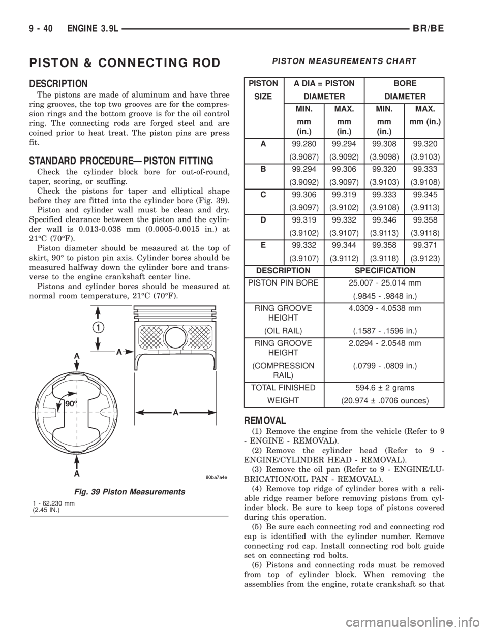
Check the pistons for taper and elliptical shape
before they are fitted into the cylinder bore (Fig. 39).
Piston and cylinder wall must be clean and dry.
Specified clearance between the piston and the cylin-
der wall is 0.013-0.038 mm (0.0005-0.0015 in.) at
21ÉC (70ÉF).
Piston diameter should be measured at the top of
skirt, 90É to piston pin axis. Cylinder bores should be
measured halfway down the cylinder bore and trans-
verse to the engine crankshaft center line.
Pistons and cylinder bores should be measured at
normal room temperature, 21ÉC (70ÉF).
PISTON MEASUREMENTS CHART
PISTON A DIA = PISTON BORE
SIZE DIAMETER DIAMETER
MIN. MAX. MIN. MAX.
mm
(in.)mm
(in.)mm
(in.)mm (in.)
A99.280 99.294 99.308 99.320
(3.9087) (3.9092) (3.9098) (3.9103)
B99.294 99.306 99.320 99.333
(3.9092) (3.9097) (3.9103) (3.9108)
C99.306 99.319 99.333 99.345
(3.9097) (3.9102) (3.9108) (3.9113)
D99.319 99.332 99.346 99.358
(3.9102) (3.9107) (3.9113) (3.9118)
E99.332 99.344 99.358 99.371
(3.9107) (3.9112) (3.9118) (3.9123)
DESCRIPTION SPECIFICATION
PISTON PIN BORE 25.007 - 25.014 mm
(.9845 - .9848 in.)
RING GROOVE
HEIGHT4.0309 - 4.0538 mm
(OIL RAIL) (.1587 - .1596 in.)
RING GROOVE
HEIGHT2.0294 - 2.0548 mm
(COMPRESSION
RAIL)(.0799 - .0809 in.)
TOTAL FINISHED 594.6 2 grams
WEIGHT (20.974 .0706 ounces)
REMOVAL
(1) Remove the engine from the vehicle (Refer to 9
- ENGINE - REMOVAL).
(2) Remove the cylinder head (Refer to 9 -
ENGINE/CYLINDER HEAD - REMOVAL).
(3) Remove the oil pan (Refer to 9 - ENGINE/LU-
BRICATION/OIL PAN - REMOVAL).
(4) Remove top ridge of cylinder bores with a reli-
able ridge reamer before removing pistons from cyl-
inder block. Be sure to keep tops of pistons covered
during this operation.
(5) Be sure each connecting rod and connecting rod
cap is identified with the cylinder number. Remove
connecting rod cap. Install connecting rod bolt guide
set on connecting rod bolts.
(6) Pistons and connecting rods must be removed
from top of cylinder block. When removing the
assemblies from the engine, rotate crankshaft so that
Fig. 39 Piston Measurements
1 - 62.230 mm
(2.45 IN.)
9 - 40 ENGINE 3.9LBR/BE
Page 1207 of 2889
FRONT MOUNT
REMOVAL.............................100
INSTALLATION..........................100
REAR MOUNT
REMOVAL.............................101
INSTALLATION..........................101
LUBRICATION
DESCRIPTION..........................102
OPERATION............................102
DIAGNOSIS AND TESTING................104
ENGINE OIL LEAKS....................104
ENGINE OIL PRESSURE................104
OIL
STANDARD PROCEDURE.................104
ENGINE OIL..........................104
OIL FILTER
REMOVAL.............................105
INSTALLATION..........................105
OIL PAN
REMOVAL.............................105
CLEANING.............................106
INSPECTION...........................106
INSTALLATION..........................106
OIL PUMP
REMOVAL.............................107
DISASSEMBLY..........................107INSPECTION...........................107
ASSEMBLY............................109
INSTALLATION..........................109
INTAKE MANIFOLD
DESCRIPTION..........................109
OPERATION............................109
DIAGNOSIS AND TESTING................110
INTAKE MANIFOLD LEAKAGE............110
REMOVAL.............................110
CLEANING.............................110
INSPECTION...........................110
INSTALLATION..........................111
EXHAUST MANIFOLD
DESCRIPTION..........................112
OPERATION............................112
REMOVAL.............................112
CLEANING.............................112
INSPECTION...........................112
INSTALLATION..........................113
TIMING BELT / CHAIN COVER(S)
REMOVAL.............................113
INSTALLATION..........................113
TIMING BELT/CHAIN AND SPROCKETS
REMOVAL.............................114
INSPECTION...........................114
INSTALLATION..........................115
ENGINE 5.2L
DESCRIPTION
The 5.2 Liter (318 CID) eight-cylinder engine is a
V-Type lightweight, single cam, overhead valve
engine with hydraulic roller tappets. This engine is
designed for unleaded fuel.
Engine lubrication system consists of a rotor type
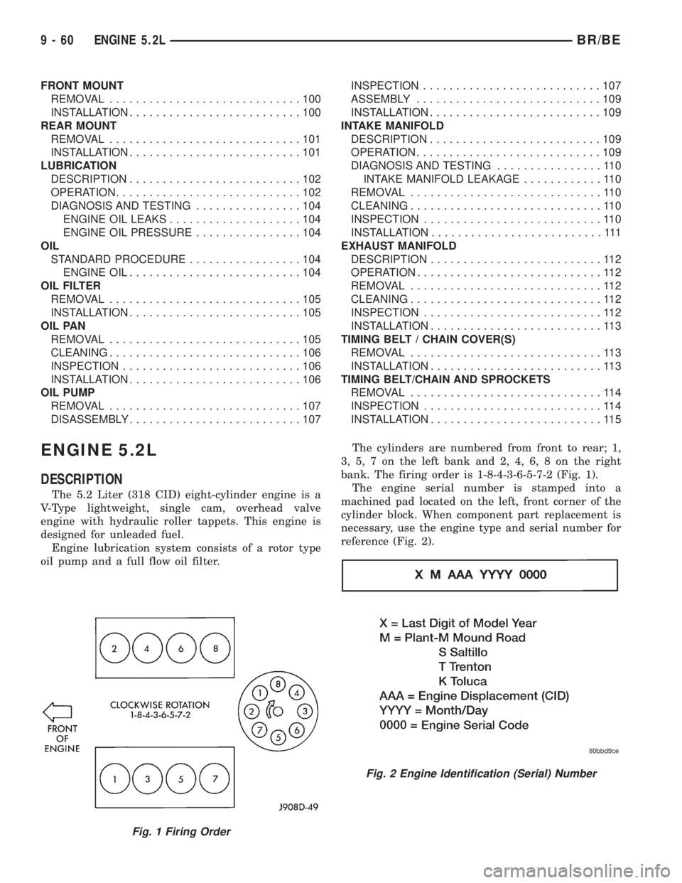
oil pump and a full flow oil filter.The cylinders are numbered from front to rear; 1,
3, 5, 7 on the left bank and 2, 4, 6, 8 on the right
bank. The firing order is 1-8-4-3-6-5-7-2 (Fig. 1).
The engine serial number is stamped into a
machined pad located on the left, front corner of the
cylinder block. When component part replacement is
necessary, use the engine type and serial number for
reference (Fig. 2).
Fig. 1 Firing Order
Fig. 2 Engine Identification (Serial) Number
9 - 60 ENGINE 5.2LBR/BE