2001 DODGE RAM coolant level
[x] Cancel search: coolant levelPage 346 of 2889
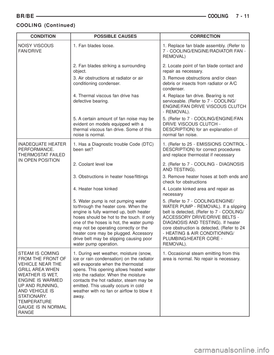
CONDITION POSSIBLE CAUSES CORRECTION
NOISY VISCOUS
FAN/DRIVE1. Fan blades loose. 1. Replace fan blade assembly. (Refer to
7 - COOLING/ENGINE/RADIATOR FAN -
REMOVAL)
2. Fan blades striking a surrounding
object.2. Locate point of fan blade contact and
repair as necessary.
3. Air obstructions at radiator or air
conditioning condenser.3. Remove obstructions and/or clean
debris or insects from radiator or A/C
condenser.
4. Thermal viscous fan drive has
defective bearing.4. Replace fan drive. Bearing is not
serviceable. (Refer to 7 - COOLING/
ENGINE/FAN DRIVE VISCOUS CLUTCH
- REMOVAL).
5. A certain amount of fan noise may be
evident on models equipped with a
thermal viscous fan drive. Some of this
noise is normal.5. (Refer to 7 - COOLING/ENGINE/FAN
DRIVE VISCOUS CLUTCH -
DESCRIPTION) for an explanation of
normal fan noise.
INADEQUATE HEATER
PERFORMANCE.
THERMOSTAT FAILED
IN OPEN POSITION1. Has a Diagnostic trouble Code (DTC)
been set?1. (Refer to 25 - EMISSIONS CONTROL -
DESCRIPTION) for correct procedures
and replace thermostat if necessary
2. Coolant level low 2. (Refer to 7 - COOLING - DIAGNOSIS
AND TESTING).
3. Obstructions in heater hose/fittings 3. Remove heater hoses at both ends and
check for obstructions
4. Heater hose kinked 4. Locate kinked area and repair as
necessary
5. Water pump is not pumping water
to/through the heater core. When the
engine is fully warmed up, both heater
hoses should be hot to the touch. If only
one of the hoses is hot, the water pump
may not be operating correctly or the
heater core may be plugged. Accessory
drive belt may be slipping causing poor
water pump operation.5. (Refer to 7 - COOLING/ENGINE/
WATER PUMP - REMOVAL). If a slipping
belt is detected, (Refer to 7 - COOLING/
ACCESSORY DRIVE/DRIVE BELTS -
DIAGNOSIS AND TESTING). If heater
core obstruction is detected, (Refer to 24
- HEATING & AIR CONDITIONING/
PLUMBING/HEATER CORE -
REMOVAL).
STEAM IS COMING
FROM THE FRONT OF
VEHICLE NEAR THE
GRILL AREA WHEN
WEATHER IS WET,
ENGINE IS WARMED
UP AND RUNNING,
AND VEHICLE IS
STATIONARY.
TEMPERATURE
GAUGE IS IN NORMAL
RANGE1. During wet weather, moisture (snow,
ice or rain condensation) on the radiator
will evaporate when the thermostat
opens. This opening allows heated water
into the radiator. When the moisture
contacts the hot radiator, steam may be
emitted. This usually occurs in cold
weather with no fan or airflow to blow it
away.1. Occasional steam emitting from this
area is normal. No repair is necessary.
BR/BECOOLING 7 - 11
COOLING (Continued)
Page 347 of 2889
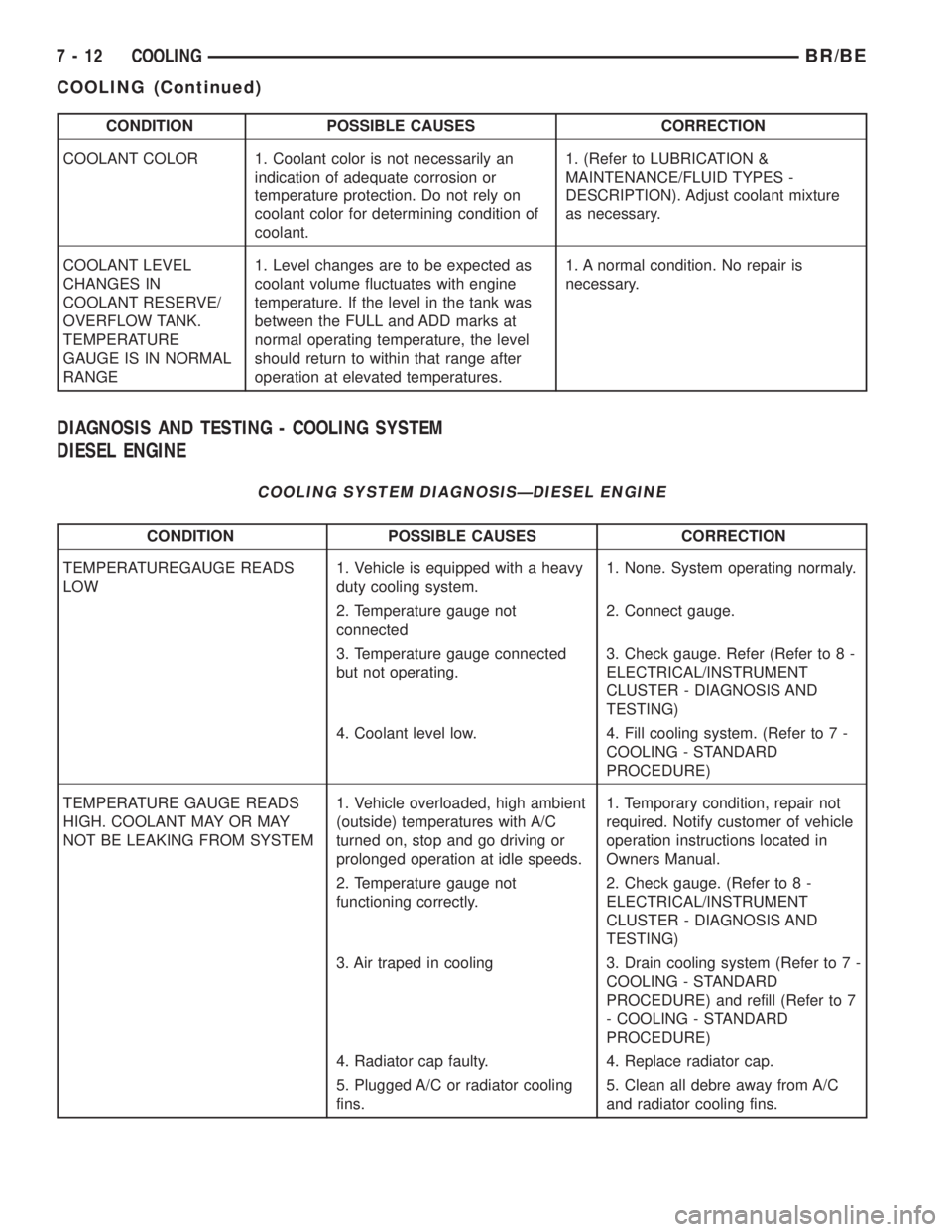
CONDITION POSSIBLE CAUSES CORRECTION
COOLANT COLOR 1. Coolant color is not necessarily an
indication of adequate corrosion or
temperature protection. Do not rely on
coolant color for determining condition of
coolant.1. (Refer to LUBRICATION &
MAINTENANCE/FLUID TYPES -
DESCRIPTION). Adjust coolant mixture
as necessary.
COOLANT LEVEL
CHANGES IN
COOLANT RESERVE/
OVERFLOW TANK.
TEMPERATURE
GAUGE IS IN NORMAL
RANGE1. Level changes are to be expected as
coolant volume fluctuates with engine
temperature. If the level in the tank was
between the FULL and ADD marks at
normal operating temperature, the level
should return to within that range after
operation at elevated temperatures.1. A normal condition. No repair is
necessary.
DIAGNOSIS AND TESTING - COOLING SYSTEM
DIESEL ENGINE
COOLING SYSTEM DIAGNOSISÐDIESEL ENGINE
CONDITION POSSIBLE CAUSES CORRECTION
TEMPERATUREGAUGE READS
LOW1. Vehicle is equipped with a heavy
duty cooling system.1. None. System operating normaly.
2. Temperature gauge not
connected2. Connect gauge.
3. Temperature gauge connected
but not operating.3. Check gauge. Refer (Refer to 8 -
ELECTRICAL/INSTRUMENT
CLUSTER - DIAGNOSIS AND
TESTING)
4. Coolant level low. 4. Fill cooling system. (Refer to 7 -
COOLING - STANDARD
PROCEDURE)
TEMPERATURE GAUGE READS
HIGH. COOLANT MAY OR MAY
NOT BE LEAKING FROM SYSTEM1. Vehicle overloaded, high ambient
(outside) temperatures with A/C
turned on, stop and go driving or
prolonged operation at idle speeds.1. Temporary condition, repair not
required. Notify customer of vehicle
operation instructions located in
Owners Manual.
2. Temperature gauge not
functioning correctly.2. Check gauge. (Refer to 8 -
ELECTRICAL/INSTRUMENT
CLUSTER - DIAGNOSIS AND
TESTING)
3. Air traped in cooling 3. Drain cooling system (Refer to 7 -
COOLING - STANDARD
PROCEDURE) and refill (Refer to 7
- COOLING - STANDARD
PROCEDURE)
4. Radiator cap faulty. 4. Replace radiator cap.
5. Plugged A/C or radiator cooling
fins.5. Clean all debre away from A/C
and radiator cooling fins.
7 - 12 COOLINGBR/BE
COOLING (Continued)
Page 350 of 2889
STANDARD PROCEDUREÐDRAINING
COOLING SYSTEM 3.9L/5.2L/5.9L/8.0L
ENGINES
WARNING: DO NOT REMOVE CYLINDER BLOCK
DRAIN PLUGS OR LOOSEN RADIATOR DRAIN-
COCK WITH SYSTEM HOT AND UNDER PRESSURE.
SERIOUS BURNS FROM COOLANT CAN OCCUR.
DO NOT WASTE reusable coolant. If solution is
clean, drain coolant into a clean container for reuse.
(1) Remove radiator pressure cap.
(2) Loosen radiator petcock.
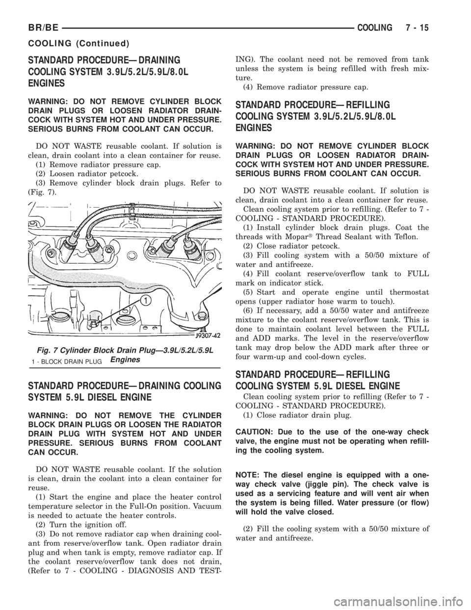
(3) Remove cylinder block drain plugs. Refer to
(Fig. 7).
STANDARD PROCEDUREÐDRAINING COOLING
SYSTEM 5.9L DIESEL ENGINE
WARNING: DO NOT REMOVE THE CYLINDER
BLOCK DRAIN PLUGS OR LOOSEN THE RADIATOR
DRAIN PLUG WITH SYSTEM HOT AND UNDER
PRESSURE. SERIOUS BURNS FROM COOLANT
CAN OCCUR.
DO NOT WASTE reusable coolant. If the solution
is clean, drain the coolant into a clean container for
reuse.
(1) Start the engine and place the heater control
temperature selector in the Full-On position. Vacuum
is needed to actuate the heater controls.
(2) Turn the ignition off.
(3) Do not remove radiator cap when draining cool-
ant from reserve/overflow tank. Open radiator drain
plug and when tank is empty, remove radiator cap. If
the coolant reserve/overflow tank does not drain,
(Refer to 7 - COOLING - DIAGNOSIS AND TEST-ING). The coolant need not be removed from tank
unless the system is being refilled with fresh mix-
ture.
(4) Remove radiator pressure cap.
STANDARD PROCEDUREÐREFILLING
COOLING SYSTEM 3.9L/5.2L/5.9L/8.0L
ENGINES
WARNING: DO NOT REMOVE CYLINDER BLOCK
DRAIN PLUGS OR LOOSEN RADIATOR DRAIN-
COCK WITH SYSTEM HOT AND UNDER PRESSURE.
SERIOUS BURNS FROM COOLANT CAN OCCUR.
DO NOT WASTE reusable coolant. If solution is
clean, drain coolant into a clean container for reuse.
Clean cooling system prior to refilling. (Refer to 7 -
COOLING - STANDARD PROCEDURE).
(1) Install cylinder block drain plugs. Coat the
threads with MopartThread Sealant with Teflon.
(2) Close radiator petcock.
(3) Fill cooling system with a 50/50 mixture of
water and antifreeze.
(4) Fill coolant reserve/overflow tank to FULL
mark on indicator stick.
(5) Start and operate engine until thermostat
opens (upper radiator hose warm to touch).
(6) If necessary, add a 50/50 water and antifreeze
mixture to the coolant reserve/overflow tank. This is
done to maintain coolant level between the FULL
and ADD marks. The level in the reserve/overflow
tank may drop below the ADD mark after three or
four warm-up and cool-down cycles.
STANDARD PROCEDUREÐREFILLING
COOLING SYSTEM 5.9L DIESEL ENGINE
Clean cooling system prior to refilling (Refer to 7 -
COOLING - STANDARD PROCEDURE).
(1) Close radiator drain plug.
CAUTION: Due to the use of the one-way check
valve, the engine must not be operating when refill-
ing the cooling system.
NOTE: The diesel engine is equipped with a one-
way check valve (jiggle pin). The check valve is
used as a servicing feature and will vent air when
the system is being filled. Water pressure (or flow)
will hold the valve closed.
(2) Fill the cooling system with a 50/50 mixture of
water and antifreeze.
Fig. 7 Cylinder Block Drain PlugÐ3.9L/5.2L/5.9L
Engines
1 - BLOCK DRAIN PLUG
BR/BECOOLING 7 - 15
COOLING (Continued)
Page 351 of 2889
(3) Fill coolant reserve/overflow tank to the FULL
mark.
(4) Start and operate engine until thermostat
opens. Upper radiator hose should be warm to touch.
(5) If necessary, add 50/50 water and antifreeze
mixture to the coolant reserve/overflow tank to main-
tain coolant level. This level should be between the
ADD and FULL marks. The level in the reserve/over-
flow tank may drop below the ADD mark after three
or four warm-up and cool-down cycles.
STANDARD PROCEDUREÐADDING
ADDITIONAL COOLANT
Do not remove radiator cap to add coolant to
system.When adding coolant to maintain correct
level, do so at coolant reserve/overflow tank. Use a
50/50 mixture of ethylene glycol antifreeze containing
Alugard 340-2yand low mineral content water.
Remove radiator cap only for testing or when refill-
ing system after service. Removing cap unnecessarily
can cause loss of coolant and allow air to enter sys-
tem, which produces corrosion.
STANDARD PROCEDUREÐCOOLANT LEVEL
CHECK
NOTE: Do not remove radiator cap for routine cool-
ant level inspections. The coolant level can be
checked at coolant recovery bottle .
The coolant reserve/overflow system provides a
quick method for determining coolant level without
removing radiator pressure cap. With engine not run-
ning, open the coolant recovery bottle cap and
remove coolant level indicator dipstick to observe
coolant level in coolant recovery bottle. The coolant
level should be between ADD and FULL marks. If
the coolant level is at or below the ADD mark, fill
the recovery bottle with a 50/50 mixture of antifreeze
and water ONE QUART AT A TIME. Repeat this pro-
cedure until the coolant level is at the FULL mark
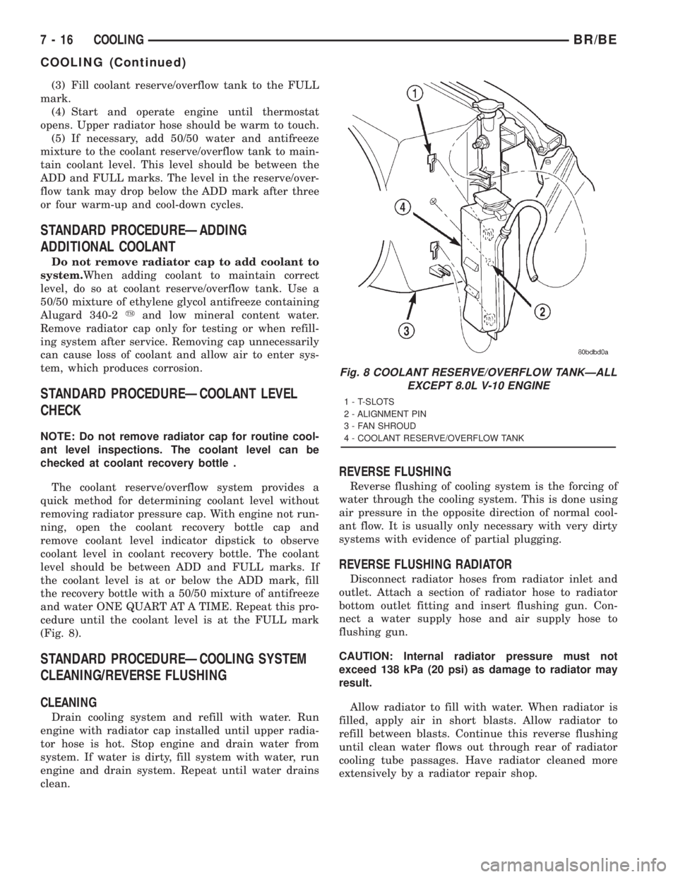
(Fig. 8).
STANDARD PROCEDUREÐCOOLING SYSTEM
CLEANING/REVERSE FLUSHING
CLEANING
Drain cooling system and refill with water. Run
engine with radiator cap installed until upper radia-
tor hose is hot. Stop engine and drain water from
system. If water is dirty, fill system with water, run
engine and drain system. Repeat until water drains
clean.
REVERSE FLUSHING
Reverse flushing of cooling system is the forcing of
water through the cooling system. This is done using
air pressure in the opposite direction of normal cool-
ant flow. It is usually only necessary with very dirty
systems with evidence of partial plugging.
REVERSE FLUSHING RADIATOR
Disconnect radiator hoses from radiator inlet and
outlet. Attach a section of radiator hose to radiator
bottom outlet fitting and insert flushing gun. Con-
nect a water supply hose and air supply hose to
flushing gun.
CAUTION: Internal radiator pressure must not
exceed 138 kPa (20 psi) as damage to radiator may
result.
Allow radiator to fill with water. When radiator is
filled, apply air in short blasts. Allow radiator to
refill between blasts. Continue this reverse flushing
until clean water flows out through rear of radiator
cooling tube passages. Have radiator cleaned more
extensively by a radiator repair shop.
Fig. 8 COOLANT RESERVE/OVERFLOW TANKÐALL
EXCEPT 8.0L V-10 ENGINE
1 - T-SLOTS
2 - ALIGNMENT PIN
3 - FAN SHROUD
4 - COOLANT RESERVE/OVERFLOW TANK
7 - 16 COOLINGBR/BE
COOLING (Continued)
Page 352 of 2889
REVERSE FLUSHING ENGINE
Drain cooling system. Remove thermostat housing
and thermostat. Install thermostat housing. Discon-
nect radiator upper hose from radiator and attach
flushing gun to hose. Disconnect radiator lower hose
from water pump and attach a lead-away hose to
water pump inlet fitting.
CAUTION: On vehicles equipped with a heater water
control valve, be sure heater control valve is closed
(heat off). This will prevent coolant flow with scale
and other deposits from entering heater core.
Connect water supply hose and air supply hose to
flushing gun. Allow engine to fill with water. When
engine is filled, apply air in short blasts, allowing
system to fill between air blasts. Continue until clean
water flows through the lead away hose.
Remove lead away hose, flushing gun, water sup-
ply hose and air supply hose. Remove thermostat
housing and install thermostat. Install thermostat
housing with a replacement gasket. Refer to Thermo-
stat Replacement. Connect radiator hoses. Refill cool-
ing system with correct antifreeze/water mixture.
Refer to Refilling the Cooling System.
CHEMICAL CLEANING
In some instances, use a radiator cleaner (Mopar
Radiator Kleen or equivalent) before flushing. This
will soften scale and other deposits and aid flushing
operation.
CAUTION: Follow manufacturers instructions when
using these products.
STANDARD PROCEDUREÐCOOLANT
SELECTION-ADDITIVES
The presence of aluminum components in the cool-
ing system requires strict corrosion protection. Main-
tain coolant at specified level with a mixture of
ethylene glycol based antifreeze and water. If coolant
becomes contaminated or looses color, drain and flush
cooling system and fill with correctly mixed solution.
CAUTION: Do not use coolant additives that are
claimed to improve engine cooling.
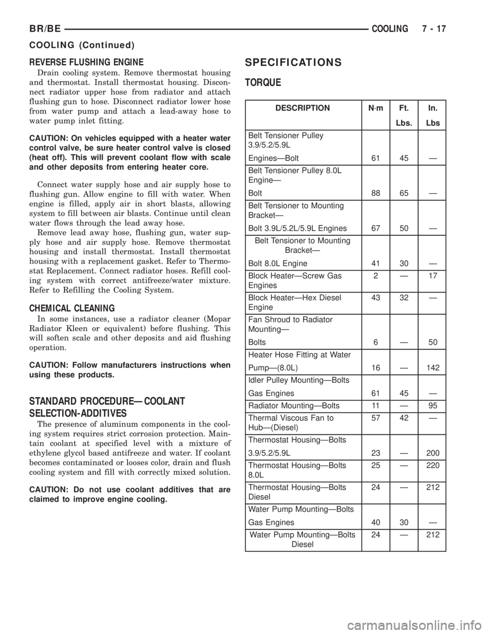
SPECIFICATIONS
TORQUE
DESCRIPTION N´m Ft. In.
Lbs. Lbs
Belt Tensioner Pulley
3.9/5.2/5.9L
EnginesÐBolt 61 45 Ð
Belt Tensioner Pulley 8.0L
EngineÐ
Bolt 88 65 Ð
Belt Tensioner to Mounting
BracketÐ
Bolt 3.9L/5.2L/5.9L Engines 67 50 Ð
Belt Tensioner to Mounting
BracketÐ
Bolt 8.0L Engine 41 30 Ð
Block HeaterÐScrew Gas
Engines2Ð17
Block HeaterÐHex Diesel
Engine43 32 Ð
Fan Shroud to Radiator
MountingÐ
Bolts 6 Ð 50
Heater Hose Fitting at Water
PumpÐ(8.0L) 16 Ð 142
Idler Pulley MountingÐBolts
Gas Engines 61 45 Ð
Radiator MountingÐBolts 11 Ð 95
Thermal Viscous Fan to
HubÐ(Diesel)57 42 Ð
Thermostat HousingÐBolts
3.9/5.2/5.9L 23 Ð 200
Thermostat HousingÐBolts
8.0L25 Ð 220
Thermostat HousingÐBolts
Diesel24 Ð 212
Water Pump MountingÐBolts
Gas Engines 40 30 Ð
Water Pump MountingÐBolts
Diesel24 Ð 212
BR/BECOOLING 7 - 17
COOLING (Continued)
Page 376 of 2889
COOLANT RECOVERY
CONTAINER - 3.9L/5.2L/5.9L/
5.9L DIESEL
DESCRIPTION
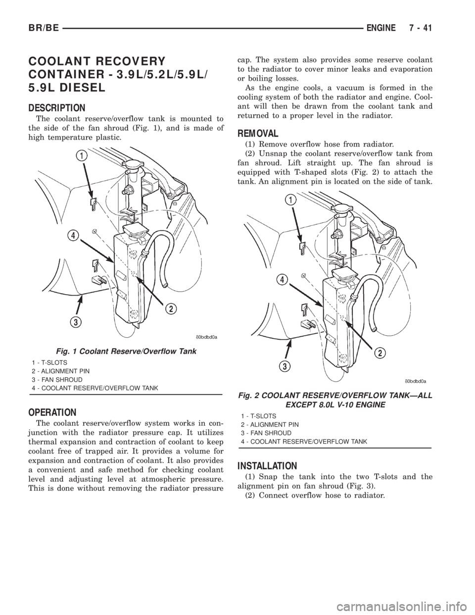
The coolant reserve/overflow tank is mounted to
the side of the fan shroud (Fig. 1), and is made of
high temperature plastic.
OPERATION
The coolant reserve/overflow system works in con-
junction with the radiator pressure cap. It utilizes
thermal expansion and contraction of coolant to keep
coolant free of trapped air. It provides a volume for
expansion and contraction of coolant. It also provides
a convenient and safe method for checking coolant
level and adjusting level at atmospheric pressure.
This is done without removing the radiator pressurecap. The system also provides some reserve coolant
to the radiator to cover minor leaks and evaporation
or boiling losses.
As the engine cools, a vacuum is formed in the
cooling system of both the radiator and engine. Cool-
ant will then be drawn from the coolant tank and
returned to a proper level in the radiator.
REMOVAL
(1) Remove overflow hose from radiator.
(2) Unsnap the coolant reserve/overflow tank from
fan shroud. Lift straight up. The fan shroud is
equipped with T-shaped slots (Fig. 2) to attach the
tank. An alignment pin is located on the side of tank.
INSTALLATION
(1) Snap the tank into the two T-slots and the
alignment pin on fan shroud (Fig. 3).
(2) Connect overflow hose to radiator.
Fig. 1 Coolant Reserve/Overflow Tank
1 - T-SLOTS
2 - ALIGNMENT PIN
3 - FAN SHROUD
4 - COOLANT RESERVE/OVERFLOW TANK
Fig. 2 COOLANT RESERVE/OVERFLOW TANKÐALL
EXCEPT 8.0L V-10 ENGINE
1 - T-SLOTS
2 - ALIGNMENT PIN
3 - FAN SHROUD
4 - COOLANT RESERVE/OVERFLOW TANK
BR/BEENGINE 7 - 41
Page 377 of 2889
COOLANT RECOVERY
CONTAINER - 8.0L
DESCRIPTION
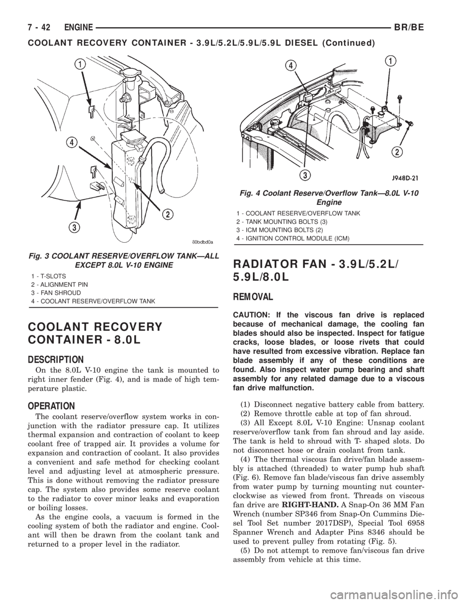
On the 8.0L V-10 engine the tank is mounted to
right inner fender (Fig. 4), and is made of high tem-
perature plastic.
OPERATION
The coolant reserve/overflow system works in con-
junction with the radiator pressure cap. It utilizes
thermal expansion and contraction of coolant to keep
coolant free of trapped air. It provides a volume for
expansion and contraction of coolant. It also provides
a convenient and safe method for checking coolant
level and adjusting level at atmospheric pressure.
This is done without removing the radiator pressure
cap. The system also provides some reserve coolant
to the radiator to cover minor leaks and evaporation
or boiling losses.
As the engine cools, a vacuum is formed in the
cooling system of both the radiator and engine. Cool-
ant will then be drawn from the coolant tank and
returned to a proper level in the radiator.
RADIATOR FAN - 3.9L/5.2L/
5.9L/8.0L
REMOVAL
CAUTION: If the viscous fan drive is replaced
because of mechanical damage, the cooling fan
blades should also be inspected. Inspect for fatigue
cracks, loose blades, or loose rivets that could
have resulted from excessive vibration. Replace fan
blade assembly if any of these conditions are
found. Also inspect water pump bearing and shaft
assembly for any related damage due to a viscous
fan drive malfunction.
(1) Disconnect negative battery cable from battery.
(2) Remove throttle cable at top of fan shroud.
(3) All Except 8.0L V-10 Engine: Unsnap coolant
reserve/overflow tank from fan shroud and lay aside.
The tank is held to shroud with T- shaped slots. Do
not disconnect hose or drain coolant from tank.
(4) The thermal viscous fan drive/fan blade assem-
bly is attached (threaded) to water pump hub shaft
(Fig. 6). Remove fan blade/viscous fan drive assembly
from water pump by turning mounting nut counter-
clockwise as viewed from front. Threads on viscous
fan drive areRIGHT-HAND.A Snap-On 36 MM Fan
Wrench (number SP346 from Snap-On Cummins Die-
sel Tool Set number 2017DSP), Special Tool 6958
Spanner Wrench and Adapter Pins 8346 should be
used to prevent pulley from rotating (Fig. 5).
(5) Do not attempt to remove fan/viscous fan drive
assembly from vehicle at this time.
Fig. 3 COOLANT RESERVE/OVERFLOW TANKÐALL
EXCEPT 8.0L V-10 ENGINE
1 - T-SLOTS
2 - ALIGNMENT PIN
3 - FAN SHROUD
4 - COOLANT RESERVE/OVERFLOW TANK
Fig. 4 Coolant Reserve/Overflow TankÐ8.0L V-10
Engine
1 - COOLANT RESERVE/OVERFLOW TANK
2 - TANK MOUNTING BOLTS (3)
3 - ICM MOUNTING BOLTS (2)
4 - IGNITION CONTROL MODULE (ICM)
7 - 42 ENGINEBR/BE
COOLANT RECOVERY CONTAINER - 3.9L/5.2L/5.9L/5.9L DIESEL (Continued)
Page 384 of 2889

ENGINE COOLANT
THERMOSTAT - 3.9L/5.2L/5.9L
DESCRIPTION
CAUTION: Do not operate an engine without a ther-
mostat, except for servicing or testing.
The thermostat on the 3.9L, 5.2L and 5.9L gas
powered engines is located beneath the thermostat
housing at the front of the intake manifold (Fig. 15).
The thermostat is a wax pellet driven, reverse pop-
pet choke type.
Coolant leakage into the pellet container will cause
the thermostat to fail in the open position. Thermo-
stats very rarely stick. Do not attempt to free a ther-
mostat with a prying device.
The same thermostat is used for winter and sum-
mer seasons. An engine should not be operated with-
out a thermostat, except for servicing or testing.
Operating without a thermostat causes longer engine
warmup time, unreliable warmup performance,
increased exhaust emissions and crankcase condensa-
tion that can result in sludge formation.
OPERATION
The wax pellet is located in a sealed container at
the spring end of the thermostat. When heated, the
pellet expands, overcoming closing spring tension
and water pump pressure to force the valve to open.
DIAGNOSIS AND TESTINGÐTHERMOSTAT
ON-BOARD DIAGNOSTICS
Allgasoline powered modelsare equipped with
On-Board Diagnostics for certain cooling system com-
ponents. Refer to On-Board Diagnostics (OBD) in the
Diagnosis section of this group for additional infor-
mation. If the powertrain control module (PCM)
detects low engine coolant temperature, it will record
a Diagnostic Trouble Code (DTC) in the PCM mem-
ory. Do not change a thermostat for lack of heat as
indicated by the instrument panel gauge or by poor
heater performance unless a DTC is present. Refer to
the Diagnosis section of this group for other probable
causes. For other DTC numbers, (Refer to 25 - EMIS-
SIONS CONTROL - DESCRIPTION).
The DTC can also be accessed through the DRB
scan tool. Refer to the appropriate Powertrain Diag-
nostic Procedures information for diagnostic informa-
tion and operation of the DRB scan tool.
REMOVAL
WARNING: DO NOT LOOSEN RADIATOR DRAIN-
COCK WITH SYSTEM HOT AND PRESSURIZED.
SERIOUS BURNS FROM COOLANT CAN OCCUR.
Do not waste reusable coolant. If solution is clean,
drain coolant into a clean container for reuse.
If thermostat is being replaced, be sure that
replacement is specified thermostat for vehicle model
and engine type.
Factory installed thermostat housings on 3.9L,
5.2L and 5.9L engines are installed on a gasket with
an anti-stick coating. This will aid in gasket removal
and clean-up.
(1) Disconnect negative battery cable at battery.
(2) Drain cooling system until coolant level is
below thermostat (Refer to 7 - COOLING - STAN-
DARD PROCEDURE).
(3) Air Conditioned vehicles: Remove support
bracket (generator mounting bracket-to-intake mani-
fold) located near rear of generator (Fig. 16).
NOTE: On air conditioning equipped vehicles, the
generator must be partially removed.
Fig. 15 ThermostatÐ5.2L and 5.9L Gas Powered
Engines
1 - THERMOSTAT HOUSING
2 - GASKET
3 - INTAKE MANIFOLD
4 - THERMOSTAT
5 - MACHINED GROOVE
BR/BEENGINE 7 - 49