2001 DODGE RAM coolant level
[x] Cancel search: coolant levelPage 2350 of 2889
INSTALLATION
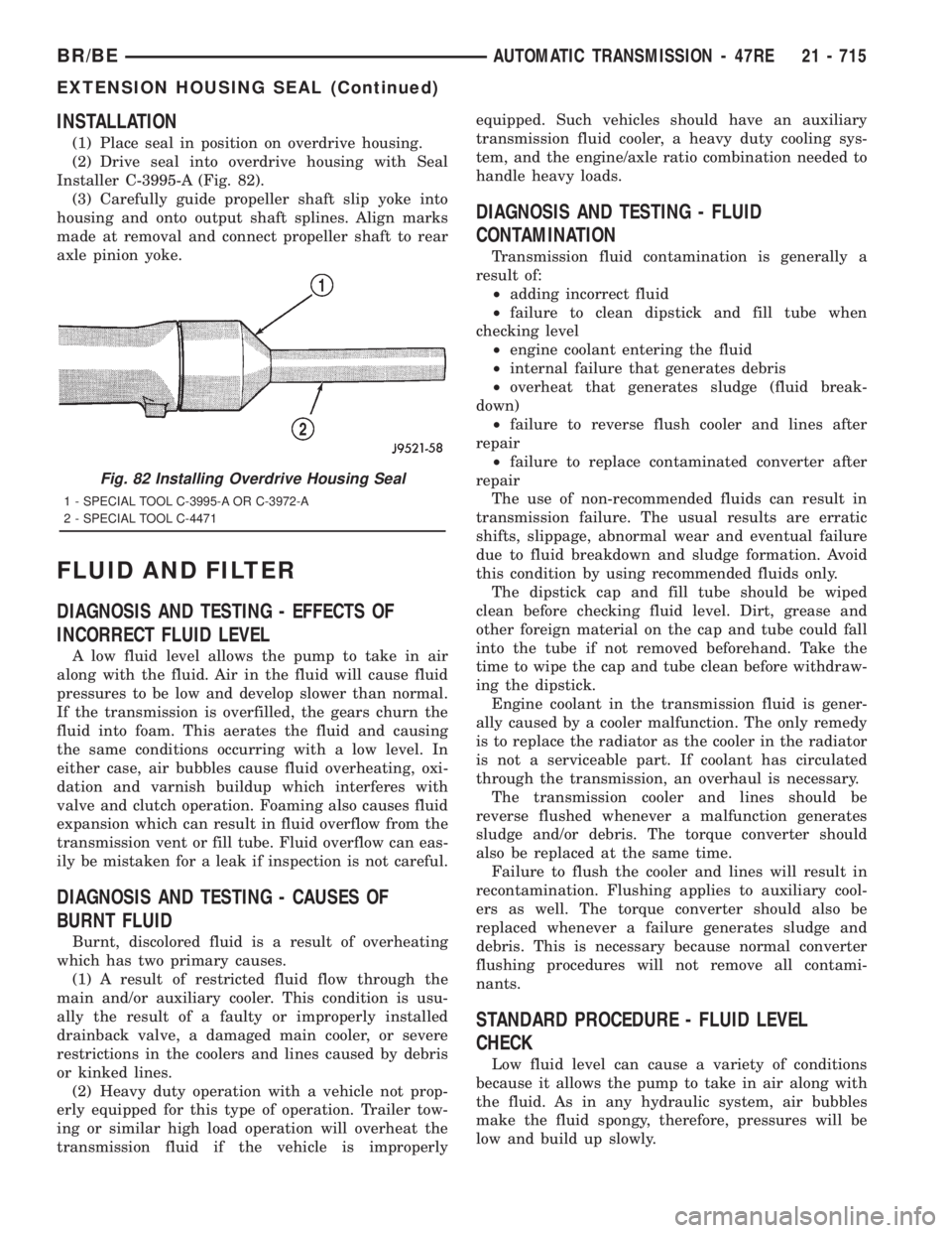
(1) Place seal in position on overdrive housing.
(2) Drive seal into overdrive housing with Seal
Installer C-3995-A (Fig. 82).
(3) Carefully guide propeller shaft slip yoke into
housing and onto output shaft splines. Align marks
made at removal and connect propeller shaft to rear
axle pinion yoke.
FLUID AND FILTER
DIAGNOSIS AND TESTING - EFFECTS OF
INCORRECT FLUID LEVEL
A low fluid level allows the pump to take in air
along with the fluid. Air in the fluid will cause fluid
pressures to be low and develop slower than normal.
If the transmission is overfilled, the gears churn the
fluid into foam. This aerates the fluid and causing
the same conditions occurring with a low level. In
either case, air bubbles cause fluid overheating, oxi-
dation and varnish buildup which interferes with
valve and clutch operation. Foaming also causes fluid
expansion which can result in fluid overflow from the
transmission vent or fill tube. Fluid overflow can eas-
ily be mistaken for a leak if inspection is not careful.
DIAGNOSIS AND TESTING - CAUSES OF
BURNT FLUID
Burnt, discolored fluid is a result of overheating
which has two primary causes.
(1) A result of restricted fluid flow through the
main and/or auxiliary cooler. This condition is usu-
ally the result of a faulty or improperly installed
drainback valve, a damaged main cooler, or severe
restrictions in the coolers and lines caused by debris
or kinked lines.
(2) Heavy duty operation with a vehicle not prop-
erly equipped for this type of operation. Trailer tow-
ing or similar high load operation will overheat the
transmission fluid if the vehicle is improperlyequipped. Such vehicles should have an auxiliary
transmission fluid cooler, a heavy duty cooling sys-
tem, and the engine/axle ratio combination needed to
handle heavy loads.
DIAGNOSIS AND TESTING - FLUID
CONTAMINATION
Transmission fluid contamination is generally a
result of:
²adding incorrect fluid
²failure to clean dipstick and fill tube when
checking level
²engine coolant entering the fluid
²internal failure that generates debris
²overheat that generates sludge (fluid break-
down)
²failure to reverse flush cooler and lines after
repair
²failure to replace contaminated converter after
repair
The use of non-recommended fluids can result in
transmission failure. The usual results are erratic
shifts, slippage, abnormal wear and eventual failure
due to fluid breakdown and sludge formation. Avoid
this condition by using recommended fluids only.
The dipstick cap and fill tube should be wiped
clean before checking fluid level. Dirt, grease and
other foreign material on the cap and tube could fall
into the tube if not removed beforehand. Take the
time to wipe the cap and tube clean before withdraw-
ing the dipstick.
Engine coolant in the transmission fluid is gener-
ally caused by a cooler malfunction. The only remedy
is to replace the radiator as the cooler in the radiator
is not a serviceable part. If coolant has circulated
through the transmission, an overhaul is necessary.
The transmission cooler and lines should be
reverse flushed whenever a malfunction generates
sludge and/or debris. The torque converter should
also be replaced at the same time.
Failure to flush the cooler and lines will result in
recontamination. Flushing applies to auxiliary cool-
ers as well. The torque converter should also be
replaced whenever a failure generates sludge and
debris. This is necessary because normal converter
flushing procedures will not remove all contami-
nants.
STANDARD PROCEDURE - FLUID LEVEL
CHECK
Low fluid level can cause a variety of conditions
because it allows the pump to take in air along with
the fluid. As in any hydraulic system, air bubbles
make the fluid spongy, therefore, pressures will be
low and build up slowly.
Fig. 82 Installing Overdrive Housing Seal
1 - SPECIAL TOOL C-3995-A OR C-3972-A
2 - SPECIAL TOOL C-4471
BR/BEAUTOMATIC TRANSMISSION - 47RE 21 - 715
EXTENSION HOUSING SEAL (Continued)
Page 2735 of 2889
DIAGNOSIS AND TESTING - HEATER
PERFORMANCE
Before performing the following tests, refer to Cool-
ing for the procedures to check the engine coolant
level and flow, engine coolant reserve/recovery sys-
tem operation, accessory drive belt condition and ten-
sion, radiator air flow and the fan drive operation.
Also be certain that the accessory vacuum supply
line is connected at the engine vacuum source.
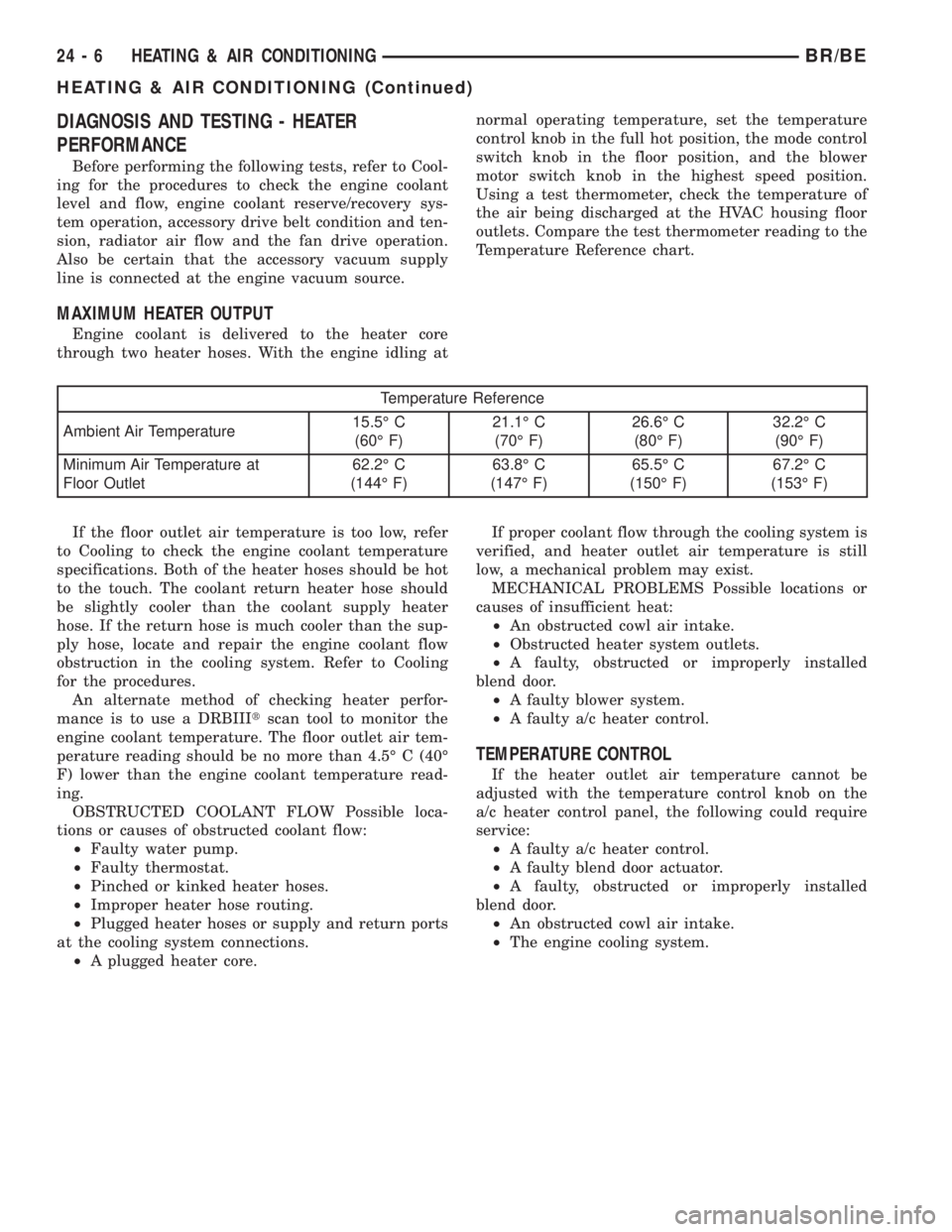
MAXIMUM HEATER OUTPUT
Engine coolant is delivered to the heater core
through two heater hoses. With the engine idling atnormal operating temperature, set the temperature
control knob in the full hot position, the mode control
switch knob in the floor position, and the blower
motor switch knob in the highest speed position.
Using a test thermometer, check the temperature of
the air being discharged at the HVAC housing floor
outlets. Compare the test thermometer reading to the
Temperature Reference chart.
Temperature Reference
Ambient Air Temperature15.5É C
(60É F)21.1É C
(70É F)26.6É C
(80É F)32.2É C
(90É F)
Minimum Air Temperature at
Floor Outlet62.2É C
(144É F)63.8É C
(147É F)65.5É C
(150É F)67.2É C
(153É F)
If the floor outlet air temperature is too low, refer
to Cooling to check the engine coolant temperature
specifications. Both of the heater hoses should be hot
to the touch. The coolant return heater hose should
be slightly cooler than the coolant supply heater
hose. If the return hose is much cooler than the sup-
ply hose, locate and repair the engine coolant flow
obstruction in the cooling system. Refer to Cooling
for the procedures.
An alternate method of checking heater perfor-
mance is to use a DRBIIItscan tool to monitor the
engine coolant temperature. The floor outlet air tem-
perature reading should be no more than 4.5É C (40É
F) lower than the engine coolant temperature read-
ing.
OBSTRUCTED COOLANT FLOW Possible loca-
tions or causes of obstructed coolant flow:
²Faulty water pump.
²Faulty thermostat.
²Pinched or kinked heater hoses.
²Improper heater hose routing.
²Plugged heater hoses or supply and return ports
at the cooling system connections.
²A plugged heater core.If proper coolant flow through the cooling system is
verified, and heater outlet air temperature is still
low, a mechanical problem may exist.
MECHANICAL PROBLEMS Possible locations or
causes of insufficient heat:
²An obstructed cowl air intake.
²Obstructed heater system outlets.
²A faulty, obstructed or improperly installed
blend door.
²A faulty blower system.
²A faulty a/c heater control.
TEMPERATURE CONTROL
If the heater outlet air temperature cannot be
adjusted with the temperature control knob on the
a/c heater control panel, the following could require
service:
²A faulty a/c heater control.
²A faulty blend door actuator.
²A faulty, obstructed or improperly installed
blend door.
²An obstructed cowl air intake.
²The engine cooling system.
24 - 6 HEATING & AIR CONDITIONINGBR/BE
HEATING & AIR CONDITIONING (Continued)
Page 2736 of 2889
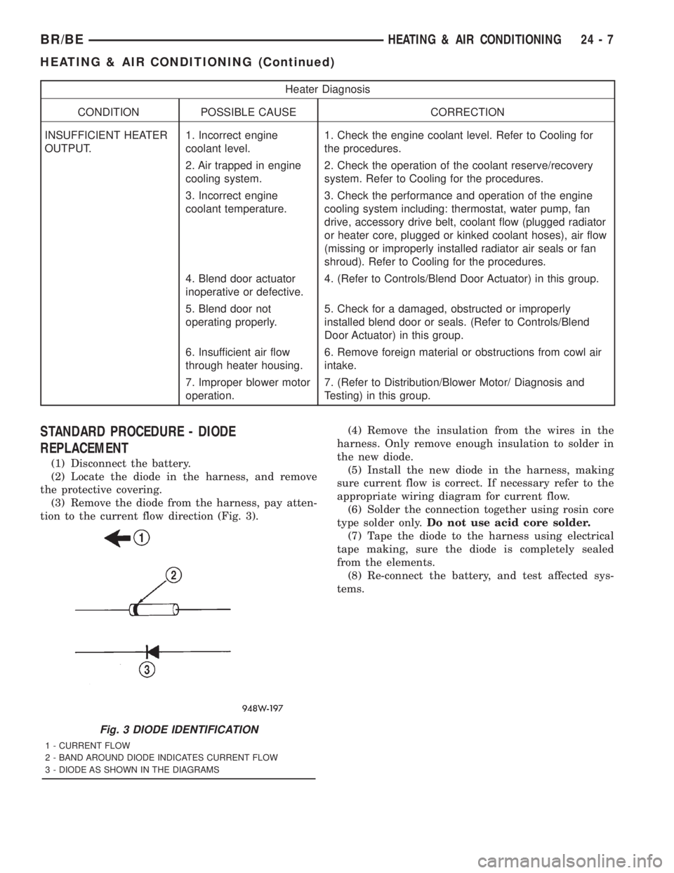
Heater Diagnosis
CONDITION POSSIBLE CAUSE CORRECTION
INSUFFICIENT HEATER
OUTPUT.1. Incorrect engine
coolant level.1. Check the engine coolant level. Refer to Cooling for
the procedures.
2. Air trapped in engine
cooling system.2. Check the operation of the coolant reserve/recovery
system. Refer to Cooling for the procedures.
3. Incorrect engine
coolant temperature.3. Check the performance and operation of the engine
cooling system including: thermostat, water pump, fan
drive, accessory drive belt, coolant flow (plugged radiator
or heater core, plugged or kinked coolant hoses), air flow
(missing or improperly installed radiator air seals or fan
shroud). Refer to Cooling for the procedures.
4. Blend door actuator
inoperative or defective.4. (Refer to Controls/Blend Door Actuator) in this group.
5. Blend door not
operating properly.5. Check for a damaged, obstructed or improperly
installed blend door or seals. (Refer to Controls/Blend
Door Actuator) in this group.
6. Insufficient air flow
through heater housing.6. Remove foreign material or obstructions from cowl air
intake.
7. Improper blower motor
operation.7. (Refer to Distribution/Blower Motor/ Diagnosis and
Testing) in this group.
STANDARD PROCEDURE - DIODE
REPLACEMENT
(1) Disconnect the battery.
(2) Locate the diode in the harness, and remove
the protective covering.
(3) Remove the diode from the harness, pay atten-
tion to the current flow direction (Fig. 3).(4) Remove the insulation from the wires in the
harness. Only remove enough insulation to solder in
the new diode.
(5) Install the new diode in the harness, making
sure current flow is correct. If necessary refer to the
appropriate wiring diagram for current flow.
(6) Solder the connection together using rosin core
type solder only.Do not use acid core solder.
(7) Tape the diode to the harness using electrical
tape making, sure the diode is completely sealed
from the elements.
(8) Re-connect the battery, and test affected sys-
tems.
Fig. 3 DIODE IDENTIFICATION
1 - CURRENT FLOW
2 - BAND AROUND DIODE INDICATES CURRENT FLOW
3 - DIODE AS SHOWN IN THE DIAGRAMS
BR/BEHEATING & AIR CONDITIONING 24 - 7
HEATING & AIR CONDITIONING (Continued)
Page 2828 of 2889
Items found requiring adjustment and/or repair
should be corrected before delivery of the vehicle.
NOTE: It is the dealer's responsibility to protect
new vehicles from damage and deterioration prior
to retail delivery both before and after new vehicle
preparation.
The information includes the following features:
Inspection points are cross-referenced to the New
Vehicle Preparation Form as follows:
²Titles indicate the general area being inspected
or the types of checks being made (i.e., underhood,
body-exterior, road test, etc.).
²Sub-Titles identify the types of items to be
inspected in that area (i.e., lines/hoses, wiring, etc.).
Procedures follow a logical order to prevent dupli-
cation and wasted effort.
Tips to help you do a better job are found as
NOTES.
RECEIVING
INSPECTION
The following procedures are recommended for
your own protection upon receipt of new vehicles.
When a new car is delivered by the carrier, it should
be inspected to ensure that it is in good condition
and to determine if there is any shortage or transpor-
tation damage.
EXTERIOR
Upon receipt of a new vehicle, check immediately
for:
²Under carriage damage
²Chipped or cracked windshield, broken windows,
and loose or missing moldings and name-plates
²Dents, scrapes, scratches, chips, dirt in paints or
other damage to the body exterior
²Damaged or missing side view mirror(s)
²Missing wheel nuts
²Broken or missing lenses
²Chafing, bruises, cuts, or scrapes on tire side-
walls or tread
²Missing underhood items
²Missing fuel filler cap
²Shipped loose items-license plate bracket, spare
tire, jack and tire wrench, radio antenna, floor mats,
wheel covers, cargo nets, fuses and other items²Ensure that IOD fuse is removed
²Check battery test indicator when easily visible,
or use voltmeter (battery must be at 12.4 volts or
greater). Charge to ensure green dot-visibility, per-
manent damage may occur if battery remains in a
discharged state for any length of time.
INTERIOR
Check interior items such as:
²Rearview mirror
²Accessory control knobs
²Smokers package items
²Keys
²Radio
²Special equipment items listed on shipper
²Owner's Manual and Consumer information Bro-
chures (normally stored in the glove box).
²Cuts, abrasions or stains on interior trim.
NOTE: Remember a careful look at new vehicles
when they are received may prevent problems when
preparing vehicles for delivery to your customers.
MAJOR INSPECTION POINTS
(1) Check operation of hood latch and safety catch-
adjust as required.
(2) Check all fluids for proper level and top off
with the proper fluid as required-engine oil, auto-
matic transmission fluid, brake master cylinder,
clutch master cylinder, power steering, windshield
washer, and cooling system. (Vehicle must be at nor-
mal operating temperature for some of these checks.)
(3) Check brake, clutch, fuel, and power steering
lines and hoses for leaks and clearance from moving
and hot objects-reroute to the proper location and
tighten as required.
(4) Check battery state of charge-recharge if neces-
sary, to ensure green dot is visible or instrument
panel voltmeter indicates 12.4 volts or greater.
(5) Check routing and connections of underhood
wiring, vacuum hoses, refrigerant lines and coolant
hoses for leaks, loose connections and clearance from
moving objects reroute and tighten connections as
required. Install IOD fuse on applicable vehicles.
NOTE: Reset radio, clock, compass, etc., after
installing, if vehicle is being delivered.
BR/BENEW VEHICLE PREPARATION 30 - 3
INTRODUCTION (Continued)
Page 2830 of 2889
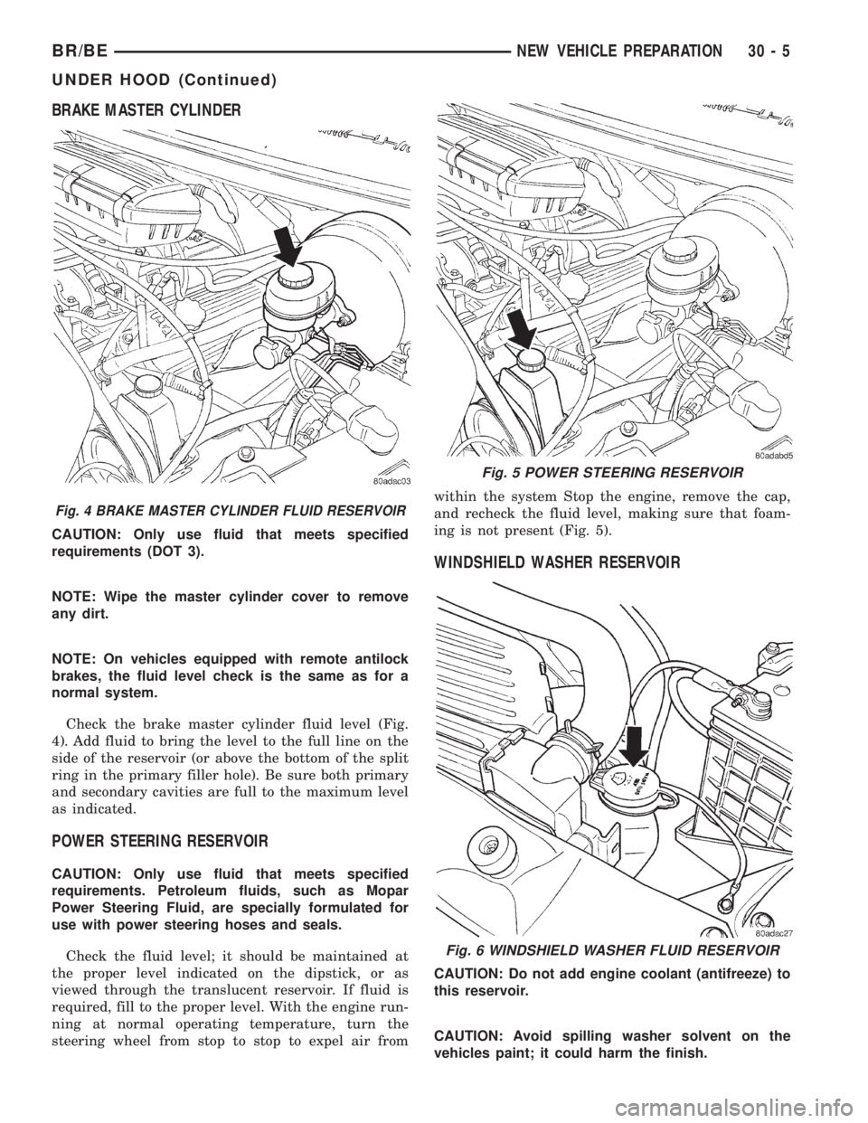
BRAKE MASTER CYLINDER
CAUTION: Only use fluid that meets specified
requirements (DOT 3).
NOTE: Wipe the master cylinder cover to remove
any dirt.
NOTE: On vehicles equipped with remote antilock
brakes, the fluid level check is the same as for a
normal system.
Check the brake master cylinder fluid level (Fig.
4). Add fluid to bring the level to the full line on the
side of the reservoir (or above the bottom of the split
ring in the primary filler hole). Be sure both primary
and secondary cavities are full to the maximum level
as indicated.
POWER STEERING RESERVOIR
CAUTION: Only use fluid that meets specified
requirements. Petroleum fluids, such as Mopar
Power Steering Fluid, are specially formulated for
use with power steering hoses and seals.
Check the fluid level; it should be maintained at
the proper level indicated on the dipstick, or as
viewed through the translucent reservoir. If fluid is
required, fill to the proper level. With the engine run-
ning at normal operating temperature, turn the
steering wheel from stop to stop to expel air fromwithin the system Stop the engine, remove the cap,
and recheck the fluid level, making sure that foam-
ing is not present (Fig. 5).
WINDSHIELD WASHER RESERVOIR
CAUTION: Do not add engine coolant (antifreeze) to
this reservoir.
CAUTION: Avoid spilling washer solvent on the
vehicles paint; it could harm the finish.
Fig. 4 BRAKE MASTER CYLINDER FLUID RESERVOIR
Fig. 5 POWER STEERING RESERVOIR
Fig. 6 WINDSHIELD WASHER FLUID RESERVOIR
BR/BENEW VEHICLE PREPARATION 30 - 5
UNDER HOOD (Continued)
Page 2831 of 2889
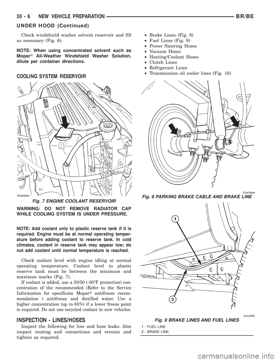
Check windshield washer solvent reservoir and fill
as necessary (Fig. 6).
NOTE: When using concentrated solvent such as
MoparTAll-Weather Windshield Washer Solution,
dilute per container directions.
COOLING SYSTEM RESERVOIR
WARNING: DO NOT REMOVE RADIATOR CAP
WHILE COOLING SYSTEM IS UNDER PRESSURE.
NOTE: Add coolant only to plastic reserve tank if it is
required. Engine must be at normal operating temper-
ature before adding coolant to reserve tank. In cold
climates, coolant in reserve tank may appear low; do
not add coolant until normal temperature is reached.
Check coolant level with engine idling at normal
operating temperature. Coolant level in plastic
reserve tank must be between the minimum and
maximun marks (Fig. 7).
If coolant is added, use a 50/50 (-309F protection) con-
centration of the recommended (Refer to the Service
Information for specificate Mopartantifreeze recom-
mendation ) antifreeze and distilled water. Use a
higher concentration (up to 65%) if a lower freeze point
is required. Do not use recycled coolant in new vehicles.
INSPECTION - LINES/HOSES
Inspect the following for line and hose leaks. Also
inspect routing and connections and reroute and
tighten as required.²Brake Lines (Fig. 8)
²Fuel Lines (Fig. 9)
²Power Steering Hoses
²Vacuum Hoses
²Heating/Coolant Hoses
²Clutch Lines
²Refrigerant Lines
²Transmission oil cooler lines (Fig. 10)
Fig. 7 ENGINE COOLANT RESERVOIRFig. 8 PARKING BRAKE CABLE AND BRAKE LINE
Fig. 9 BRAKE LINES AND FUEL LINES
1 - FUEL LINE
2 - BRAKE LINE
30 - 6 NEW VEHICLE PREPARATIONBR/BE
UNDER HOOD (Continued)
Page 2845 of 2889
STANDARD PROCEDURE - PRE DELIVERY
STORAGE
(1) If possible, store vehicles indoors, in clean, dry
places. If vehicles must be stored outdoors:
²Try to avoid storage locations that are near any
obvious sources of industrial or environmental con-
tamination (e.g., trees, factories, steam or vapor
vents, railroad tracks, etc.)
²Maintain tight security to help prevent pilferage
and vandalism, and inspect each vehicle regularly to
check for such damage
²If the vehicle must be parked on an incline, park
it with the front end higher than the rear; this will
prevent ªhydrostatic lockº caused by fuel draining
into the engine
²Rinse the vehicle at least once a week. Snow
should be washed away more often, since it can trap
harmful contaminants. Dry all horizontal surfaces
(2) The IOD fuse should be removed in order to
prevent battery drain and possible damage.
(3) Check the vehicle's coolant and anti-freeze pro-
tection.
(4) Check the vehicle's battery at least once a
month for a proper charge (at least 12.4 volts).
Charge the battery if necessary. This will help pre-
vent freezing and deterioration.
(5) Check the vehicle's tires and inflate them to
their maximum recommended levels. Move the vehi-
cles periodically to avoid ªflatspottingº the tires.
(6) Do not engage the parking brake; keep it in the
OFF position.
(7) Keep all windows closed, all doors locked, and
all trim covers intact and in place.
(8) Do not use chalks, crayons or any marker con-
taining abrasives on painted, plated or glass sur-
faces.
(9) Always use seat covers when moving a vehicle.
PROGRAMMABLE
ELECTRONIC FEATURES
DESCRIPTION
The programming of electronic features applies to
specific DaimlerChrysler Corporation vehicles. Not
all vehicles are equipped with these electronic fea-
tures, and not all vehicles equipped with electronic
features have all the available features. Programma-
ble electronic features are subject to change and may
be added or deleted from specific vehicle models.
(1) The programmable electronic features that may
be provided on the vehicle are:
²Rolling Power Door Locks
²Horn Chirp (When Doors Locked With Remote
Keyless Entry)²Headlamp Flash (When Doors Locked or
Unlocked With Remote Keyless Entry)
²Low Fuel Chime
²Remote Keyless Entry Door Unlock Sequence
²Headlights On Automatically With Wipers
²Turn Signal Chime
²12V Power Outlet
²Remote Unlock
²Remote Linked To Memory
²Headlamp Delay
²Service Interval
²Easy Exit Seat
(2) Programming any of the above features is to be
performed prior to vehicle delivery to the customer,
depending on customer preference.
NOTE: For all vehicles except Caravan/Town and
Country, the programming must be performed using
the DRB IIITscan tool. On Caravan/Town and Coun-
try vehicles the features can be programmed using
the DRB IIITscan tool or by button pushing
sequences. The customer can perform program-
ming, if desired, by following the instructions out-
lined in the owner manual.
OPERATION
NOTE: The programmable features provided on
vehicles need to be explained to the customer at
the time of sale. The customer's preferences con-
cerning the features should be noted and pro-
grammed accordingly during predelivery.
NOTE: When using the DRB IIITscan tool to enable/
disable any programmable electronic features, go to
the main menu item #9 on the DRB IIITscan tool.
This is ªCustomer Preferencesº. You must choose
ªCustomer Preferencesº on the main menu to pro-
gram the desired features.
ROLLING POWER DOOR LOCKS
With this feature enabled, the vehicle's door lock-
ing mechanisms automatically lock when the vehicle
reaches approximately 24 Km/h (15 mph).
HORN CHIRP
NOTE: This feature can be enabled with or without
the headlamp flash feature.
The horn chirp function is a feature that can be
enabled or disabled on vehicles equipped with
30 - 20 NEW VEHICLE PREPARATIONBR/BE
PRE DELIVERY STORAGE (Continued)
Page 2854 of 2889
CENTER HIGH MOUNTED STOP LAMP -
INSTALLATION........................8L-6
CENTER HIGH MOUNTED STOP LAMP -
REMOVAL...........................8L-6
CENTER HIGH MOUNTED STOP LAMP
UNIT - INSTALLATION..................8L-6
CENTER HIGH MOUNTED STOP LAMP
UNIT - REMOVAL.....................8L-6
CENTER SEAT ARMREST/CONSOLE -
INSTALLATION......................23-132
CENTER SEAT ARMREST/CONSOLE -
REMOVAL.........................23-132
CENTER SEAT ARMREST/LATCH COVER -
INSTALLATION......................23-132
CENTER SEAT ARMREST/LATCH COVER -
REMOVAL.........................23-132
CENTERING - STANDARD PROCEDURE,
CLOCKSPRING......................8O-11
CENTRAL TIMER MODULE - DIAGNOSIS
AND TESTING........................8E-4
CERTIFICATION LABEL - DESCRIPTION,
VEHICLE SAFETY..................Intro.-12
CHAIN COVER(S) - INSTALLATION,
TIMING BELT..........9-113,9-169,9-226,9-56
CHAIN COVER(S) - REMOVAL, TIMING
BELT ................9-113,9-169,9-225,9-56
CHAIN STRETCH - INSPECTION,
MEASURING TIMING....9-114,9-170,9-227,9-58
CHANNEL - INSTALLATION, GLASS RUN . . 23-70
CHANNEL - REMOVAL, GLASS RUN......23-70
CHARGE - STANDARD PROCEDURE,
REFRIGERANT SYSTEM...............24-46
CHARGE AIR COOLER AND PLUMBING -
CLEANING..........................11-18
CHARGE AIR COOLER AND PLUMBING -
DESCRIPTION.......................11-17
CHARGE AIR COOLER AND PLUMBING -
INSPECTION........................11-18
CHARGE AIR COOLER AND PLUMBING -
INSTALLATION.......................11-18
CHARGE AIR COOLER AND PLUMBING -
OPERATION.........................11-17
CHARGE AIR COOLER AND PLUMBING -
REMOVAL..........................11-17
CHARGING - DESCRIPTION.............8F-27
CHARGING - OPERATION..............8F-27
CHARGING - STANDARD PROCEDURE,
BATTERY............................8F-9
CHARGING SYSTEM - DIAGNOSIS AND
TESTING...........................8F-27
CHART, SPECIFICATIONS - TORQUE........5-3
CHART, SPECIFICATIONS -
TORQUE.............19-19,19-39,19-41,19-9
CHART, SPECIFICATIONS -
TORQUE.....................2-15,2-27,2-8
CHART, SPECIFICATIONS - TORQUE......22-11
CHARTS - DIAGNOSIS AND TESTING,
DIAGNOSIS......21-149,21-320,21-492,21-663
CHARTS - DIAGNOSIS AND TESTING,
SMOKE DIAGNOSIS...................9-234
CHASSIS ADAPTER BRACKET -
INSTALLATION, CAB...................13-9
CHASSIS ADAPTER BRACKET -
REMOVAL, CAB.......................13-9
CHECK - INSTALLATION...............23-78
CHECK - REMOVAL...................23-78
CHECK - STANDARD PROCEDURE,
COOLANT LEVEL......................7-16
CHECK - STANDARD PROCEDURE, FLUID
LEVEL..........21-199,21-370,21-545,21-715
CHECK - STANDARD PROCEDURE, OIL
PUMP VOLUME . . . 21-209,21-379,21-554,21-724
CHECK CABLE - INSTALLATION.........23-63
CHECK CABLE - REMOVAL.............23-62
CHECK GAUGES INDICATOR -
DESCRIPTION.......................8J-17
CHECK GAUGES INDICATOR -
OPERATION.........................8J-17
CHECK OUT - STANDARD PROCEDURE,
OWNER............................30-22
CHECK VALVE - DESCRIPTION, ONE WAY . 25-30
CHECK VALVE - DESCRIPTION, VACUUM
. . 24-28
CHECK VALVE - DIAGNOSIS AND
TESTING, ONE-WAY
..................25-30
CHECK VALVE - INSTALLATION, ONE
WAY
...............................25-30
CHECK VALVE - INSTALLATION, VACUUM
. 24-29
CHECK VALVE - OPERATION, ONE WAY
. . . 25-30CHECK VALVE - OPERATION, VACUUM....24-28
CHECK VALVE - REMOVAL, ONE WAY....25-30
CHECK VALVE - REMOVAL, VACUUM.....24-29
CHECKING BATTERY ELECTROLYTE
LEVEL - STANDARD PROCEDURE.........8F-8
CHECKING TRANSMISSION CLUTCH AND
BAND OPERATION - DIAGNOSIS AND
TESTING, AIR................21-147,21-318
CHECKS - DIAGNOSIS AND TESTING,
PRELIMINARY.........................7-4
CHILD TETHER - INSTALLATION..........8O-9
CHILD TETHER - REMOVAL.............8O-9
CHIME WARNING SYSTEM -
DESCRIPTION........................8B-1
CHIME WARNING SYSTEM - DIAGNOSIS
AND TESTING........................8B-2
CHIME WARNING SYSTEM - OPERATION . . . 8B-1
CHOKE RELAY - DESCRIPTION, RADIO....8A-8
CHOKE RELAY - DIAGNOSIS AND
TESTING, RADIO......................8A-8
CHOKE RELAY - INSTALLATION, RADIO....8A-9
CHOKE RELAY - OPERATION, RADIO......8A-8
CHOKE RELAY - REMOVAL, RADIO.......8A-9
CIGAR LIGHTER - DIAGNOSIS &
TESTING.........................8W-97-2
CIGAR LIGHTER OUTLET - DESCRIPTION . 8W-97-2
CIGAR LIGHTER OUTLET -
INSTALLATION....................8W-97-3
CIGAR LIGHTER OUTLET - OPERATION . 8W-97-2
CIGAR LIGHTER OUTLET - REMOVAL....8W-97-3
CIRCUIT ACTUATION TEST MODE -
DESCRIPTION........................25-1
CIRCUIT BREAKER - DESCRIPTION....8W-97-4
CIRCUIT BREAKER - DIAGNOSIS &
TESTING.........................8W-97-4
CIRCUIT SENSE - DESCRIPTION,
IGNITION...........................8E-17
CIRCUIT SENSE - OPERATION, IGNITION . . 8E-19
CIRCUITS - DIESEL - OPERATION,
NON-MONITORED....................25-23
CIRCUITS - GAS ENGINES - OPERATION,
NON-MONITORED....................25-22
CLAMPS - DESCRIPTION, HOSE...........7-2
CLAMPS - OPERATION, HOSE.............7-2
CLASSIFICATION OF LUBRICANTS -
STANDARD PROCEDURE.................0-3
CLEANER ELEMENT - INSTALLATION,
AIR ...............................9-245
CLEANER ELEMENT - REMOVAL, AIR.....9-244
CLEANING AND INSPECTION, OIL
COOLER & LINES....................9-296
CLEANING, APPEARANCE TIPS..........30-21
CLEANING/REVERSE FLUSHING -
STANDARD PROCEDURE, COOLING
SYSTEM............................7-16
CLEARANCE - STANDARD PROCEDURE,
CONNECTING ROD BEARING AND
CRANKSHAFT JOURNAL...............9-274
CLEARANCE - STANDARD PROCEDURE,
MAIN BEARING......................9-275
CLEARANCE LAMP - INSTALLATION.......8L-6
CLEARANCE LAMP - REMOVAL..........8L-6
CLOCKSPRING - DESCRIPTION.........8O-10
CLOCKSPRING - INSTALLATION.........8O-13
CLOCKSPRING - OPERATION...........8O-10
CLOCKSPRING - REMOVAL............8O-11
CLOCKSPRING CENTERING - STANDARD
PROCEDURE........................8O-11
CLOSURE PANEL TRIM - INSTALLATION,
REAR.............................23-121
CLOSURE PANEL TRIM - REMOVAL,
REAR.............................23-120
CLUB/QUAD CAB - INSTALLATION.......8O-20
CLUB/QUAD CAB - REMOVAL...........8O-19
CLUSTER - ASSEMBLY, INSTRUMENT....8J-13
CLUSTER - DESCRIPTION, INSTRUMENT . . . 8J-2
CLUSTER - DIAGNOSIS AND TESTING,
INSTRUMENT........................8J-6
CLUSTER - DISASSEMBLY, INSTRUMENT . . 8J-11
CLUSTER - INSTALLATION, INSTRUMENT . 8J-14
CLUSTER - OPERATION, INSTRUMENT.....8J-3
CLUSTER - REMOVAL, INSTRUMENT
.....8J-10
CLUSTER BEZEL - INSTALLATION
.......23-110
CLUSTER BEZEL - REMOVAL
..........23-109
CLUTCH - 3.9L/5.2L/5.9L/8.0L -
DESCRIPTION, FAN DRIVE VISCOUS
......7-56
CLUTCH - 3.9L/5.2L/5.9L/8.0L -
OPERATION, FAN DRIVE VISCOUS
........7-56CLUTCH - 5.9L DIESEL - DESCRIPTION,
FAN DRIVE VISCOUS...................7-57
CLUTCH - 5.9L DIESEL - OPERATION,
FAN DRIVE VISCOUS...................7-57
CLUTCH - ASSEMBLY, FRONT . . . 21-206,21-376,
21-550,21-721
CLUTCH - ASSEMBLY, REAR....21-248,21-419,
21-593,21-766
CLUTCH - CLEANING, REAR....21-247,21-418,
21-593,21-765
CLUTCH - DESCRIPTION.................6-1
CLUTCH - DESCRIPTION, A/C
COMPRESSOR.......................24-13
CLUTCH - DESCRIPTION, FRONT . 21-202,21-373,
21-548,21-718
CLUTCH - DESCRIPTION, OVERDRIVE . . . 21-214,
21-385,21-560,21-731
CLUTCH - DESCRIPTION, REAR . . 21-246,21-417,
21-591,21-764
CLUTCH - DIAGNOSTIC AND TESTING......6-2
CLUTCH - DISASSEMBLY, FRONT......21-202,
21-373,21-549,21-719
CLUTCH - DISASSEMBLY, REAR . 21-247,21-418,
21-592,21-765
CLUTCH - INSPECTION, A/C
COMPRESSOR.......................24-16
CLUTCH - INSPECTION, FRONT . . 21-205,21-376,
21-550,21-721
CLUTCH - INSPECTION, REAR . . . 21-248,21-419,
21-593,21-765
CLUTCH - INSTALLATION, A/C
COMPRESSOR.......................24-16
CLUTCH - OPERATION....................6-1
CLUTCH - OPERATION, A/C
COMPRESSOR.......................24-13
CLUTCH - OPERATION, FRONT . . 21-202,21-373,
21-548,21-718
CLUTCH - OPERATION, OVERDRIVE....21-214,
21-385,21-560,21-731
CLUTCH - OPERATION, REAR . . . 21-246,21-417,
21-592,21-764
CLUTCH - REMOVAL, A/C COMPRESSOR . . 24-14
CLUTCH - SPECIFICATIONS...............6-7
CLUTCH - WARNING....................6-2
CLUTCH AND BAND OPERATION -
DIAGNOSIS AND TESTING, AIR
CHECKING TRANSMISSION......21-147,21-318
CLUTCH AND BAND OPERATION -
DIAGNOSIS AND TESTING, AIR
TESTING TRANSMISSION.......21-490,21-661
CLUTCH BREAK-IN - STANDARD
PROCEDURE, A/C COMPRESSOR........24-13
CLUTCH CAM/OVERDRIVE PISTON
RETAINER - ASSEMBLY,
OVERRUNNING . . . 21-236,21-406,21-581,21-752
CLUTCH CAM/OVERDRIVE PISTON
RETAINER - CLEANING, OVERRUNNING . 21-236,
21-406,21-580,21-752
CLUTCH CAM/OVERDRIVE PISTON
RETAINER - DESCRIPTION,
OVERRUNNING . . . 21-235,21-405,21-580,21-751
CLUTCH CAM/OVERDRIVE PISTON
RETAINER - DISASSEMBLY,
OVERRUNNING . . . 21-235,21-405,21-580,21-751
CLUTCH CAM/OVERDRIVE PISTON
RETAINER - INSPECTION,
OVERRUNNING . . . 21-236,21-406,21-580,21-752
CLUTCH CAM/OVERDRIVE PISTON
RETAINER - OPERATION,
OVERRUNNING . . . 21-235,21-405,21-580,21-751
CLUTCH COIL - DIAGNOSIS AND
TESTING, A/C COMPRESSOR...........24-13
CLUTCH DISC - DESCRIPTION............6-7
CLUTCH DISC - INSTALLATION............6-9
CLUTCH DISC - OPERATION..............6-8
CLUTCH DISC - REMOVAL...............6-8
CLUTCH HOUSING - DIAGNOSIS AND
TESTING............................6-11
CLUTCH HOUSING - INSTALLATION.......6-13
CLUTCH HOUSING - REMOVAL...........6-13
CLUTCH PEDAL - INSTALLATION
.........6-19
CLUTCH PEDAL - REMOVAL
.............6-18
CLUTCH PEDAL POSITION SWITCH -
DESCRIPTION
........................6-22
CLUTCH PEDAL POSITION SWITCH -
OPERATION
..........................6-22
CLUTCH RELAY - DESCRIPTION, A/C
COMPRESSOR
.......................24-17
BR/BEINDEX 7
Description Group-Page Description Group-Page Description Group-Page