2001 DODGE RAM timing belt
[x] Cancel search: timing beltPage 551 of 2889

filled coils. The rear coil pack contains two indepen-
dent epoxy filled coils.
OPERATION - 3.9L/5.2L/5.9L
The Powertrain Control Module (PCM) opens and
closes the ignition coil ground circuit for ignition coil
operation.
Battery voltage is supplied to the ignition coil pos-
itive terminal from the ASD relay. If the PCM does
not see a signal from the crankshaft and camshaft
sensors (indicating the ignition key is ON but the
engine is not running), it will shut down the ASD cir-
cuit.
Base ignition timing is not adjustable on any
engine.By controlling the coil ground circuit, the
PCM is able to set the base timing and adjust the
ignition timing advance. This is done to meet chang-
ing engine operating conditions.
OPERATION - 8.0L
When one of the 5 independent coils discharges, it
fires two paired cylinders at the same time (one cyl-
inder on compression stroke and the other cylinder
on exhaust stroke).
Coil firing is paired together on cylinders:
²Number 5 and 10
²Number 9 and 8
²Number 1 and 6
²Number 7 and 4
²Number 3 and 2
The ignition system is controlled by the Powertrain
Control Module (PCM) on all engines.
Battery voltage is supplied to all of the ignition
coils positive terminals from the ASD relay. If the
PCM does not see a signal from the crankshaft and
camshaft sensors (indicating the ignition key is ONbut the engine is not running), it will shut down the
ASD circuit.
Base ignition timing is not adjustable on the
8.0L V-10 engine.By controlling the coil ground cir-
cuit, the PCM is able to set the base timing and
adjust the ignition timing advance. This is done to
meet changing engine operating conditions.
The PCM adjusts ignition timing based on inputs it
receives from:
²The engine coolant temperature sensor
²The crankshaft position sensor (engine speed)
²The manifold absolute pressure (MAP) sensor
²The throttle position sensor
²Transmission gear selection
REMOVAL - 3.9L/5.2L/5.9L
The ignition coil is an epoxy filled type. If the coil
is replaced, it must be replaced with the same type.
3.9L V-6 or 5.2/5.9L V-8 LDC-Gas Engines: The coil
is mounted to a bracket that is bolted to the front of
the right engine cylinder head (Fig. 25). This bracket
is mounted on top of the automatic belt tensioner
bracket using common bolts.
5.9L V-8 HDC-Gas Engine: The coil is mounted to
a bracket that is bolted to the air injection pump
(AIR pump) mounting bracket (Fig. 26).
(1) Disconnect the primary wiring from the igni-
tion coil.
(2) Disconnect the secondary spark plug cable from
the ignition coil.
Fig. 24 Ignition Coil PacksÐ8.0L V-10 Engine
Fig. 25 Ignition CoilÐ3.9L V-6 or 5.2/5.9L V-8
LDC-Gas Engines
1 - ACCESSORY DRIVE BELT TENSIONER
2 - COIL CONNECTOR
3 - IGNITION COIL
4 - COIL MOUNTING BOLTS
8I - 14 IGNITION CONTROLBR/BE
IGNITION COIL (Continued)
Page 1149 of 2889
INSTALLATION...........................34
CRANKSHAFT OIL SEAL - REAR
DESCRIPTION...........................34
OPERATION.............................34
REMOVAL..............................35
INSTALLATION...........................35
DISTRIBUTOR BUSHING
REMOVAL..............................37
INSTALLATION...........................37
HYDRAULIC LIFTERS (CAM IN BLOCK)
DIAGNOSIS AND TESTING.................38
HYDRAULIC TAPPETS...................38
REMOVAL..............................39
CLEANING..............................39
INSTALLATION...........................39
PISTON & CONNECTING ROD
DESCRIPTION...........................40
STANDARD PROCEDURE..................40
PISTON FITTING.......................40
REMOVAL..............................40
CLEANING..............................41
INSPECTION............................41
INSTALLATION...........................41
PISTON RINGS
STANDARD PROCEDURE..................41
PISTON RING FITTING..................41
VIBRATION DAMPER
REMOVAL..............................42
INSTALLATION...........................42
FRONT MOUNT
REMOVAL..............................43
INSTALLATION...........................43
REAR MOUNT
REMOVAL..............................44
INSTALLATION...........................44
LUBRICATION
DESCRIPTION...........................45
OPERATION.............................45
DIAGNOSIS AND TESTING.................47
ENGINE OIL PRESSURE.................47
ENGINE OIL LEAKS.....................47
OIL
STANDARD PROCEDURE..................47
ENGINE OIL...........................47OIL FILTER
REMOVAL..............................48
INSTALLATION...........................48
OIL PAN
REMOVAL..............................48
CLEANING..............................49
INSPECTION............................49
INSTALLATION...........................49
OIL PRESSURE SENSOR/SWITCH
DESCRIPTION...........................49
OPERATION.............................49
OIL PUMP
REMOVAL..............................50
DISASSEMBLY...........................50
CLEANING..............................50
INSPECTION............................50
ASSEMBLY.............................51
INSTALLATION...........................52
INTAKE MANIFOLD
DESCRIPTION...........................52
OPERATION.............................52
DIAGNOSIS AND TESTING.................53
INTAKE MANIFOLD LEAKAGE.............53
REMOVAL..............................53
CLEANING..............................53
INSPECTION............................53
INSTALLATION...........................53
EXHAUST MANIFOLD
DESCRIPTION...........................55
OPERATION.............................55
REMOVAL..............................55
CLEANING..............................55
INSPECTION............................55
INSTALLATION...........................55
TIMING BELT / CHAIN COVER(S)
REMOVAL..............................56
INSTALLATION...........................56
TIMING BELT/CHAIN TENSIONER
DESCRIPTION...........................57
OPERATION.............................57
TIMING BELT/CHAIN AND SPROCKETS
REMOVAL..............................57
INSPECTION............................58
INSTALLATION...........................58
9 - 2 ENGINE 3.9LBR/BE
Page 1151 of 2889
DIAGNOSIS AND TESTINGÐPERFORMANCE
PERFORMANCE DIAGNOSIS CHARTÐGASOLINE ENGINES
CONDITION POSSIBLE CAUSES CORRECTION
ENGINE WILL NOT
CRANK1. Weak or dead battery 1. Charge/Replace Battery. (Refer to 8 -
ELECTRICAL/BATTERY SYSTEM/
BATTERY - STANDARD PROCEDURE).
Check charging system. (Refer to 8 -
ELECTRICAL/CHARGING - DIAGNOSIS
AND TESTING).
2. Corroded or loose battery
connections2. Clean/tighten suspect battery/starter
connections
3. Faulty starter or related circuit(s) 3. Check starting system. (Refer to 8 -
ELECTRICAL/STARTING - DIAGNOSIS
AND TESTING)
4. Seized accessory drive component 4. Remove accessory drive belt and
attempt to start engine. If engine starts,
repair/replace seized component.
5. Engine internal mechanical failure or
hydro-static lock5. Refer to (Refer to 9 - ENGINE -
DIAGNOSIS AND TESTING)
ENGINE CRANKS BUT
WILL NOT START1. No spark 1. Check for spark. (Refer to 8 -
ELECTRICAL/IGNITION CONTROL -
DESCRIPTION)
2. No fuel 2. Perform fuel pressure test, and if
necessary, inspect fuel injector(s) and
driver circuits. (Refer to 14 - FUEL
SYSTEM/FUEL DELIVERY/FUEL PUMP
- DIAGNOSIS AND TESTING).
3. Low or no engine compression 3. Perform cylinder compression pressure
test. (Refer to 9 - ENGINE - DIAGNOSIS
AND TESTING).
ENGINE LOSS OF
POWER1. Worn or burned distributor rotor 1. Install new distributor rotor
2. Worn distributor shaft 2. Remove and repair distributor (Refer to
8 - ELECTRICAL/IGNITION CONTROL/
DISTRIBUTOR - REMOVAL).
3. Worn or incorrect gapped spark
plugs3. Clean plugs and set gap. (Refer to 8 -
ELECTRICAL/IGNITION CONTROL/
SPARK PLUG - CLEANING).
4. Dirt or water in fuel system 4. Clean system and replace fuel filter
5. Faulty fuel pump 5. Install new fuel pump
6. Incorrect valve timing 6. Correct valve timing
7. Blown cylinder head gasket 7. Install new cylinder head gasket
8. Low compression 8. Test cylinder compression (Refer to 9 -
ENGINE - DIAGNOSIS AND TESTING).
9. Burned, warped, or pitted valves 9. Install/Reface valves as necessary
10. Plugged or restricted exhaust
system10. Install new parts as necessary
9 - 4 ENGINE 3.9LBR/BE
ENGINE 3.9L (Continued)
Page 1176 of 2889
Bearing Mount Adhesive. Plug should be 54.0 to 57.7
mm (2-1/8 to 2-5/16 in.) from bottom of the block.
CAMSHAFT & BEARINGS (IN
BLOCK)
REMOVALÐCAMSHAFT BEARINGS
(1) With engine completely disassembled, drive out
rear cam bearing core hole plug.
(2) Install proper size adapters and horseshoe
washers (part of Camshaft Bearing Remover/Installer
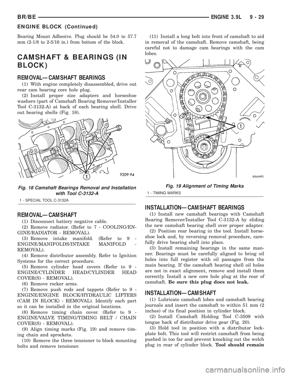
Tool C-3132-A) at back of each bearing shell. Drive
out bearing shells (Fig. 18).
REMOVALÐCAMSHAFT
(1) Disconnect battery negative cable.
(2) Remove radiator. (Refer to 7 - COOLING/EN-
GINE/RADIATOR - REMOVAL).
(3) Remove intake manifold. (Refer to 9 -
ENGINE/MANIFOLDS/INTAKE MANIFOLD -
REMOVAL).
(4) Remove distributor assembly. Refer to Ignition
Systems for the correct procedure.
(5) Remove cylinder head covers (Refer to 9 -
ENGINE/CYLINDER HEAD/CYLINDER HEAD
COVER(S) - REMOVAL).
(6) Remove rocker arms.
(7) Remove push rods and tappets (Refer to 9 -
ENGINE/ENGINE BLOCK/HYDRAULIC LIFTERS
(CAM IN BLOCK) - REMOVAL). Identify each part
so it can be installed in the original locations.
(8) Remove timing chain cover. (Refer to 9 -
ENGINE/VALVE TIMING/TIMING BELT / CHAIN
COVER(S) - REMOVAL).
(9) Align timing marks (Fig. 19) and remove tim-
ing chain and sprockets.
(10) Remove the three tensioner to block mounting
bolts and remove tensioner.(11) Install a long bolt into front of camshaft to aid
in removal of the camshaft. Remove camshaft, being
careful not to damage cam bearings with the cam
lobes.
INSTALLATIONÐCAMSHAFT BEARINGS
(1) Install new camshaft bearings with Camshaft
Bearing Remover/Installer Tool C-3132-A by sliding
the new camshaft bearing shell over proper adapter.
(2) Position rear bearing in the tool. Install horse-
shoe lock and, by reversing removal procedure, care-
fully drive bearing shell into place.
(3) Install remaining bearings in the same man-
ner. Bearings must be carefully aligned to bring oil
holes into full register with oil passages from the
main bearing. If the camshaft bearing shell oil holes
are not in exact alignment, remove and install them
correctly. Install a new core hole plug at the rear of
camshaft.Be sure this plug does not leak.
INSTALLATIONÐCAMSHAFT
(1) Lubricate camshaft lobes and camshaft bearing
journals and insert the camshaft to within 51 mm (2
inches) of its final position in cylinder block.
(2) Install Camshaft Holding Tool C-3509 with
tongue back of distributor drive gear (Fig. 20).
(3) Hold tool in position with a distributor lock-
plate bolt. This tool will restrict camshaft from being
pushed in too far and prevent knocking out the welch
plug in rear of cylinder block.Tool should remain
Fig. 18 Camshaft Bearings Removal and Installation
with Tool C-3132-A
1 - SPECIAL TOOL C-3132A
Fig. 19 Alignment of Timing Marks
1 - TIMING MARKS
BR/BEENGINE 3.9L 9 - 29
ENGINE BLOCK (Continued)
Page 1178 of 2889
(8) Turn crankshaft and camshaft to line up with
keyway location in crankshaft sprocket and in cam-
shaft sprocket.
(9) Lift sprockets and chain (keep sprockets tight
against the chain in position as described).
(10) Slide both sprockets evenly over their respec-
tive shafts and use a straightedge to check alignment
of timing marks (Fig. 22).
(11) Install the camshaft bolt/cup washer. Tighten
bolt to 68 N´m (50 ft. lbs.) torque.
(12) Measure camshaft end play (Fig. 23). (Refer to
9 - ENGINE - SPECIFICATIONS) for proper clear-
ance. If not within limits, install a new timing chain
tensioner.
(13) Each tappet reused must be installed in the
same position at which it was removed.When cam-
shaft is replaced, all of the tappets must be
replaced.Install hydraulic tappets (Refer to 9 -
ENGINE/ENGINE BLOCK/HYDRAULIC LIFTERS
(CAM IN BLOCK) - INSTALLATION).
(14) Install timing chain cover (Refer to 9 -
ENGINE/VALVE TIMING/TIMING BELT / CHAIN
COVER(S) - INSTALLATION).
(15) Install intake manifold (Refer to 9 - ENGINE/
MANIFOLDS/INTAKE MANIFOLD - INSTALLA-
TION).
(16) Install distributor.
(17) Install cylinder head covers (Refer to 9 -
ENGINE/CYLINDER HEAD/CYLINDER HEAD
COVER(S) - INSTALLATION).
(18) Install radiator (Refer to 7 - COOLING/EN-
GINE/RADIATOR - INSTALLATION).
(19) Fill cooling system (Refer to 7 - COOLING -
STANDARD PROCEDURE).
(20) Connect battery negative cable.
(21) Start engine and check for leaks.
CONNECTING ROD BEARINGS
STANDARD PROCEDURE-CONNECTING ROD
BEARING FITTING
Fit all rods on a bank until completed. DO NOT
alternate from one bank to another, because connect-
ing rods and pistons are not interchangeable from
one bank to another.
The bearing caps are not interchangeable and
should be marked at removal to ensure correct
assembly.
Each bearing cap has a small V-groove across the
parting face. When installing the lower bearing shell,
be certain that the V-groove in the shell is in line
with the V-groove in the cap. This provides lubrica-
tion of the cylinder wall in the opposite bank.The bearing shells must be installed so that the
tangs are in the machined grooves in the rods and
caps.
Limits of taper or out-of-round on any crankshaft
journals should be held to 0.025 mm (0.001 in.).
Bearings are available in 0.025 mm (0.001 in.), 0.051
mm (0.002 in.), 0.076 mm (0.003 in.), 0.254 mm
(0.010 in.) and 0.305 mm (0.012 in.) undersize.
Install the bearings in pairs. DO NOT use a new
bearing half with an old bearing half. DO NOT
file the rods or bearing caps.
CRANKSHAFT
DESCRIPTION
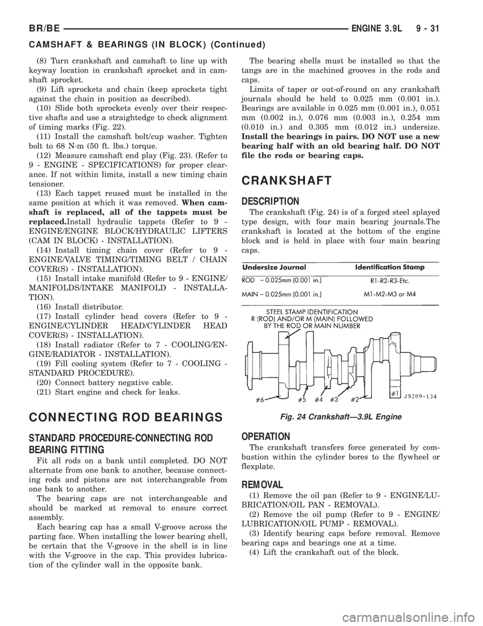
The crankshaft (Fig. 24) is of a forged steel splayed
type design, with four main bearing journals.The
crankshaft is located at the bottom of the engine
block and is held in place with four main bearing
caps.
OPERATION
The crankshaft transfers force generated by com-
bustion within the cylinder bores to the flywheel or
flexplate.
REMOVAL
(1) Remove the oil pan (Refer to 9 - ENGINE/LU-
BRICATION/OIL PAN - REMOVAL).
(2) Remove the oil pump (Refer to 9 - ENGINE/
LUBRICATION/OIL PUMP - REMOVAL).
(3) Identify bearing caps before removal. Remove
bearing caps and bearings one at a time.
(4) Lift the crankshaft out of the block.
Fig. 24 CrankshaftÐ3.9L Engine
BR/BEENGINE 3.9L 9 - 31
CAMSHAFT & BEARINGS (IN BLOCK) (Continued)
Page 1203 of 2889
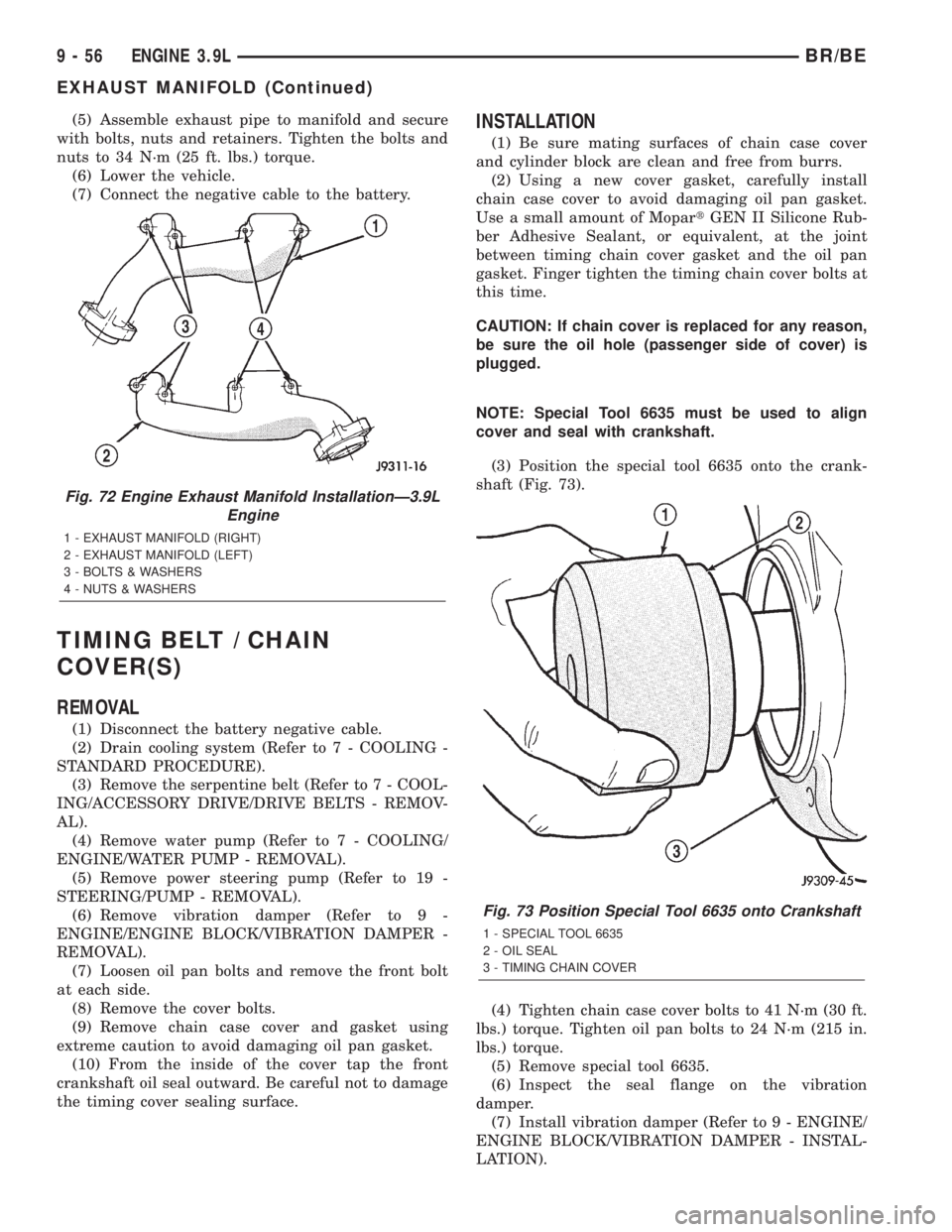
(5) Assemble exhaust pipe to manifold and secure
with bolts, nuts and retainers. Tighten the bolts and
nuts to 34 N´m (25 ft. lbs.) torque.
(6) Lower the vehicle.
(7) Connect the negative cable to the battery.
TIMING BELT / CHAIN
COVER(S)
REMOVAL
(1) Disconnect the battery negative cable.
(2) Drain cooling system (Refer to 7 - COOLING -
STANDARD PROCEDURE).
(3) Remove the serpentine belt (Refer to 7 - COOL-
ING/ACCESSORY DRIVE/DRIVE BELTS - REMOV-
AL).
(4) Remove water pump (Refer to 7 - COOLING/
ENGINE/WATER PUMP - REMOVAL).
(5) Remove power steering pump (Refer to 19 -
STEERING/PUMP - REMOVAL).
(6) Remove vibration damper (Refer to 9 -
ENGINE/ENGINE BLOCK/VIBRATION DAMPER -
REMOVAL).
(7) Loosen oil pan bolts and remove the front bolt
at each side.
(8) Remove the cover bolts.
(9) Remove chain case cover and gasket using
extreme caution to avoid damaging oil pan gasket.
(10) From the inside of the cover tap the front
crankshaft oil seal outward. Be careful not to damage
the timing cover sealing surface.
INSTALLATION
(1) Be sure mating surfaces of chain case cover
and cylinder block are clean and free from burrs.
(2) Using a new cover gasket, carefully install
chain case cover to avoid damaging oil pan gasket.
Use a small amount of MopartGEN II Silicone Rub-
ber Adhesive Sealant, or equivalent, at the joint
between timing chain cover gasket and the oil pan
gasket. Finger tighten the timing chain cover bolts at
this time.
CAUTION: If chain cover is replaced for any reason,
be sure the oil hole (passenger side of cover) is
plugged.
NOTE: Special Tool 6635 must be used to align
cover and seal with crankshaft.
(3) Position the special tool 6635 onto the crank-
shaft (Fig. 73).
(4) Tighten chain case cover bolts to 41 N´m (30 ft.
lbs.) torque. Tighten oil pan bolts to 24 N´m (215 in.
lbs.) torque.
(5) Remove special tool 6635.
(6) Inspect the seal flange on the vibration
damper.
(7) Install vibration damper (Refer to 9 - ENGINE/
ENGINE BLOCK/VIBRATION DAMPER - INSTAL-
LATION).
Fig. 72 Engine Exhaust Manifold InstallationÐ3.9L
Engine
1 - EXHAUST MANIFOLD (RIGHT)
2 - EXHAUST MANIFOLD (LEFT)
3 - BOLTS & WASHERS
4 - NUTS & WASHERS
Fig. 73 Position Special Tool 6635 onto Crankshaft
1 - SPECIAL TOOL 6635
2 - OIL SEAL
3 - TIMING CHAIN COVER
9 - 56 ENGINE 3.9LBR/BE
EXHAUST MANIFOLD (Continued)
Page 1204 of 2889
(8) Install water pump (Refer to 7 - COOLING/EN-
GINE/WATER PUMP - INSTALLATION).
(9) Install power steering pump (Refer to 19 -
STEERING/PUMP - INSTALLATION).
(10) Install the serpentine belt (Refer to 7 - COOL-
ING/ACCESSORY DRIVE/DRIVE BELTS - INSTAL-
LATION).
(11) Install the cooling system fan (Refer to 7 -
COOLING/ENGINE/FAN DRIVE VISCOUS
CLUTCH - INSTALLATION).
(12) Position the fan shroud and install the bolts.
Tighten the bolts to 11 N´m (95 in. lbs.) torque.
(13) Fill cooling system (Refer to 7 - COOLING -
STANDARD PROCEDURE).
(14) Connect the negative cable to the battery.
TIMING BELT/CHAIN
TENSIONER
DESCRIPTION
The timing chain tensioner is a stamped steel con-
stant tension mechanical design. It is mounted to the
front of the engine, behind the timing chain drive.
OPERATION
The timing chain tension is maintained by routing
the timing chain through the tensioner assembly. A
nylon covered spring steel arm presses on the timing
chain maintaining the correct chain tension.
TIMING BELT/CHAIN AND
SPROCKETS
REMOVAL
(1) Disconnect battery negative cable.
(2) Drain cooling system (Refer to 7 - COOLING -
STANDARD PROCEDURE).
(3) Remove timing chain cover (Refer to 9 -
ENGINE/VALVE TIMING/TIMING BELT / CHAIN
COVER(S) - REMOVAL).
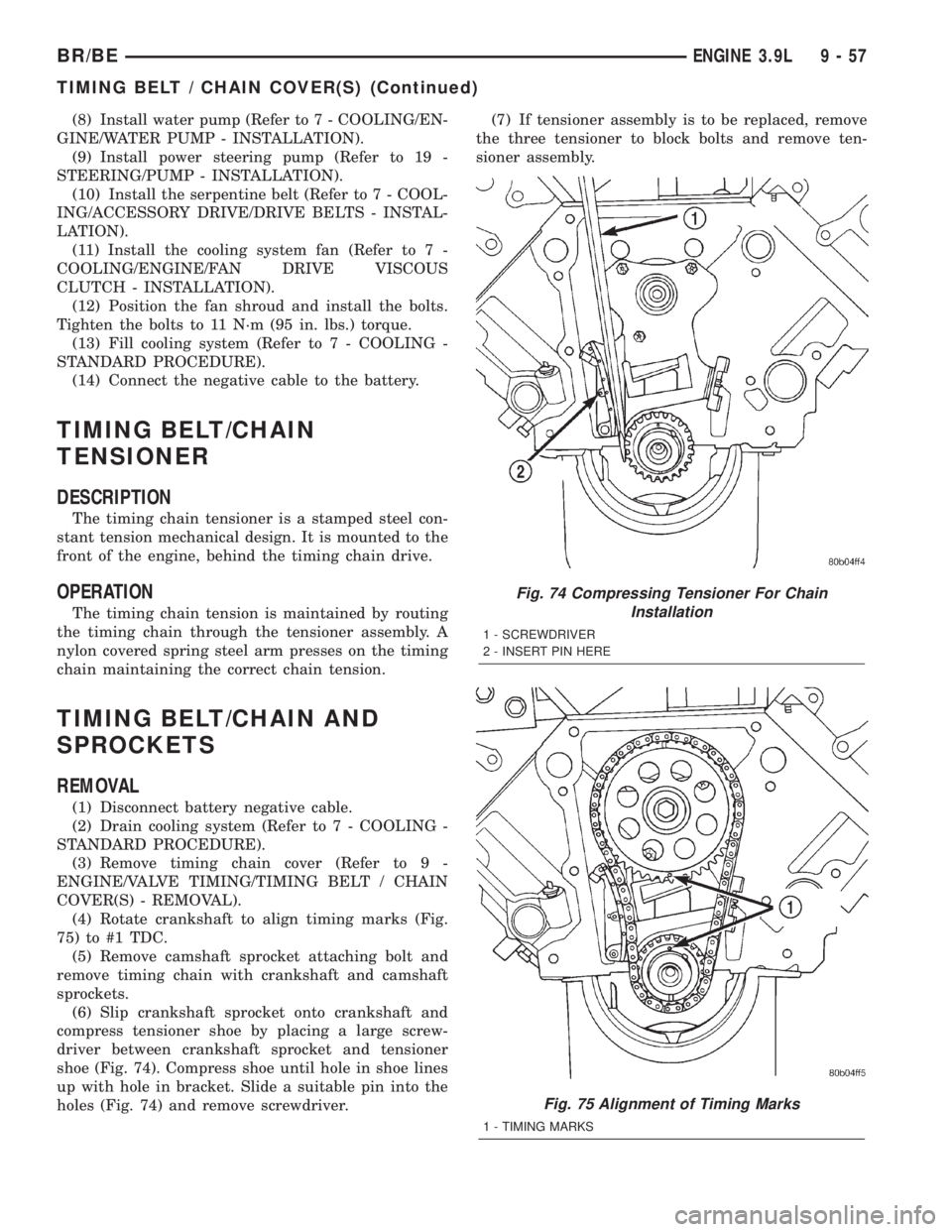
(4) Rotate crankshaft to align timing marks (Fig.
75) to #1 TDC.
(5) Remove camshaft sprocket attaching bolt and
remove timing chain with crankshaft and camshaft
sprockets.
(6) Slip crankshaft sprocket onto crankshaft and
compress tensioner shoe by placing a large screw-
driver between crankshaft sprocket and tensioner
shoe (Fig. 74). Compress shoe until hole in shoe lines
up with hole in bracket. Slide a suitable pin into the
holes (Fig. 74) and remove screwdriver.(7) If tensioner assembly is to be replaced, remove
the three tensioner to block bolts and remove ten-
sioner assembly.
Fig. 74 Compressing Tensioner For Chain
Installation
1 - SCREWDRIVER
2 - INSERT PIN HERE
Fig. 75 Alignment of Timing Marks
1 - TIMING MARKS
BR/BEENGINE 3.9L 9 - 57
TIMING BELT / CHAIN COVER(S) (Continued)
Page 1205 of 2889
INSPECTIONÐMEASURING TIMING CHAIN
STRETCH
NOTE: Timing chain tensioner must be removed for
this operation.
(1) Place a scale next to the timing chain so that
any movement of the chain can be measured.
(2) Place a torque wrench and socket over cam-
shaft sprocket attaching bolt. Apply torque in the
direction of crankshaft rotation to take up slack; 41
N´m (30 ft. lbs.) torque with cylinder head installed
or 20 N´m (15 ft. lbs.) torque with cylinder head
removed. With torque applied to the camshaft
sprocket bolt, crankshaft should not be permitted to
move. It may be necessary to block the crankshaft to
prevent rotation.
(3) Hold a scale with dimensional reading even
with the edge of a chain link. With cylinder heads
installed, apply 14 N´m (30 ft. lbs.) torque in the
reverse direction. With the cylinder heads removed,
apply 20 N´m (15 ft. lbs.) torque in the reverse direc-
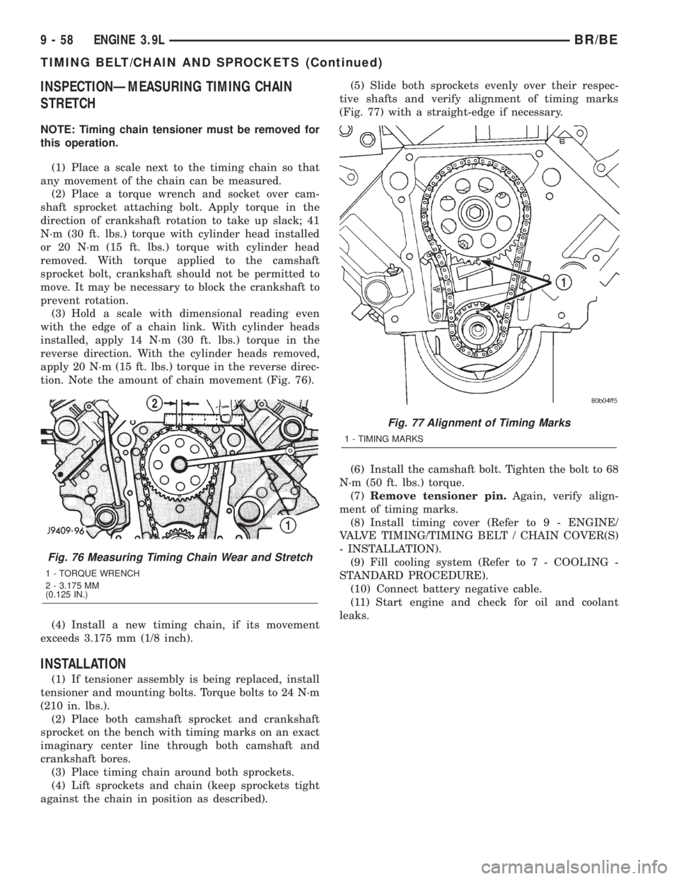
tion. Note the amount of chain movement (Fig. 76).
(4) Install a new timing chain, if its movement
exceeds 3.175 mm (1/8 inch).
INSTALLATION
(1) If tensioner assembly is being replaced, install
tensioner and mounting bolts. Torque bolts to 24 N´m
(210 in. lbs.).
(2) Place both camshaft sprocket and crankshaft
sprocket on the bench with timing marks on an exact
imaginary center line through both camshaft and
crankshaft bores.
(3) Place timing chain around both sprockets.
(4) Lift sprockets and chain (keep sprockets tight
against the chain in position as described).(5) Slide both sprockets evenly over their respec-
tive shafts and verify alignment of timing marks
(Fig. 77) with a straight-edge if necessary.
(6) Install the camshaft bolt. Tighten the bolt to 68
N´m (50 ft. lbs.) torque.
(7)Remove tensioner pin.Again, verify align-
ment of timing marks.
(8) Install timing cover (Refer to 9 - ENGINE/
VALVE TIMING/TIMING BELT / CHAIN COVER(S)
- INSTALLATION).
(9) Fill cooling system (Refer to 7 - COOLING -
STANDARD PROCEDURE).
(10) Connect battery negative cable.
(11) Start engine and check for oil and coolant
leaks.
Fig. 76 Measuring Timing Chain Wear and Stretch
1 - TORQUE WRENCH
2 - 3.175 MM
(0.125 IN.)
Fig. 77 Alignment of Timing Marks
1 - TIMING MARKS
9 - 58 ENGINE 3.9LBR/BE
TIMING BELT/CHAIN AND SPROCKETS (Continued)