2001 DODGE RAM timing belt
[x] Cancel search: timing beltPage 1207 of 2889
FRONT MOUNT
REMOVAL.............................100
INSTALLATION..........................100
REAR MOUNT
REMOVAL.............................101
INSTALLATION..........................101
LUBRICATION
DESCRIPTION..........................102
OPERATION............................102
DIAGNOSIS AND TESTING................104
ENGINE OIL LEAKS....................104
ENGINE OIL PRESSURE................104
OIL
STANDARD PROCEDURE.................104
ENGINE OIL..........................104
OIL FILTER
REMOVAL.............................105
INSTALLATION..........................105
OIL PAN
REMOVAL.............................105
CLEANING.............................106
INSPECTION...........................106
INSTALLATION..........................106
OIL PUMP
REMOVAL.............................107
DISASSEMBLY..........................107INSPECTION...........................107
ASSEMBLY............................109
INSTALLATION..........................109
INTAKE MANIFOLD
DESCRIPTION..........................109
OPERATION............................109
DIAGNOSIS AND TESTING................110
INTAKE MANIFOLD LEAKAGE............110
REMOVAL.............................110
CLEANING.............................110
INSPECTION...........................110
INSTALLATION..........................111
EXHAUST MANIFOLD
DESCRIPTION..........................112
OPERATION............................112
REMOVAL.............................112
CLEANING.............................112
INSPECTION...........................112
INSTALLATION..........................113
TIMING BELT / CHAIN COVER(S)
REMOVAL.............................113
INSTALLATION..........................113
TIMING BELT/CHAIN AND SPROCKETS
REMOVAL.............................114
INSPECTION...........................114
INSTALLATION..........................115
ENGINE 5.2L
DESCRIPTION
The 5.2 Liter (318 CID) eight-cylinder engine is a
V-Type lightweight, single cam, overhead valve
engine with hydraulic roller tappets. This engine is
designed for unleaded fuel.
Engine lubrication system consists of a rotor type
oil pump and a full flow oil filter.The cylinders are numbered from front to rear; 1,
3, 5, 7 on the left bank and 2, 4, 6, 8 on the right
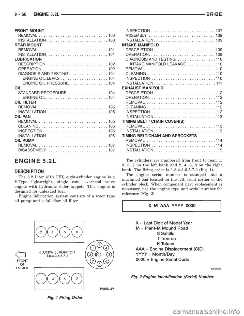
bank. The firing order is 1-8-4-3-6-5-7-2 (Fig. 1).
The engine serial number is stamped into a
machined pad located on the left, front corner of the
cylinder block. When component part replacement is
necessary, use the engine type and serial number for
reference (Fig. 2).
Fig. 1 Firing Order
Fig. 2 Engine Identification (Serial) Number
9 - 60 ENGINE 5.2LBR/BE
Page 1234 of 2889
(1) Remove the radiator (Refer to 7 - COOLING/
ENGINE/RADIATOR - REMOVAL).
(2) Remove the A/C Condenser (if equipped)
(3) Remove the engine cover.
(4) Remove intake manifold (Refer to 9 - ENGINE/
MANIFOLDS/INTAKE MANIFOLD - REMOVAL).
(5) Remove cylinder head covers (Refer to 9 -
ENGINE/CYLINDER HEAD/CYLINDER HEAD
COVER(S) - REMOVAL).
(6) Remove timing case cover (Refer to 9 -
ENGINE/VALVE TIMING/TIMING BELT / CHAIN
COVER(S) - REMOVAL) and timing chain (Refer to 9
- ENGINE/VALVE TIMING/TIMING BELT/CHAIN
AND SPROCKETS - REMOVAL).
(7) Remove rocker arms.
(8) Remove push rods and tappets. Identify each
part so it can be installed in its original location.
(9) Remove distributor and lift out the oil pump
and distributor drive shaft.
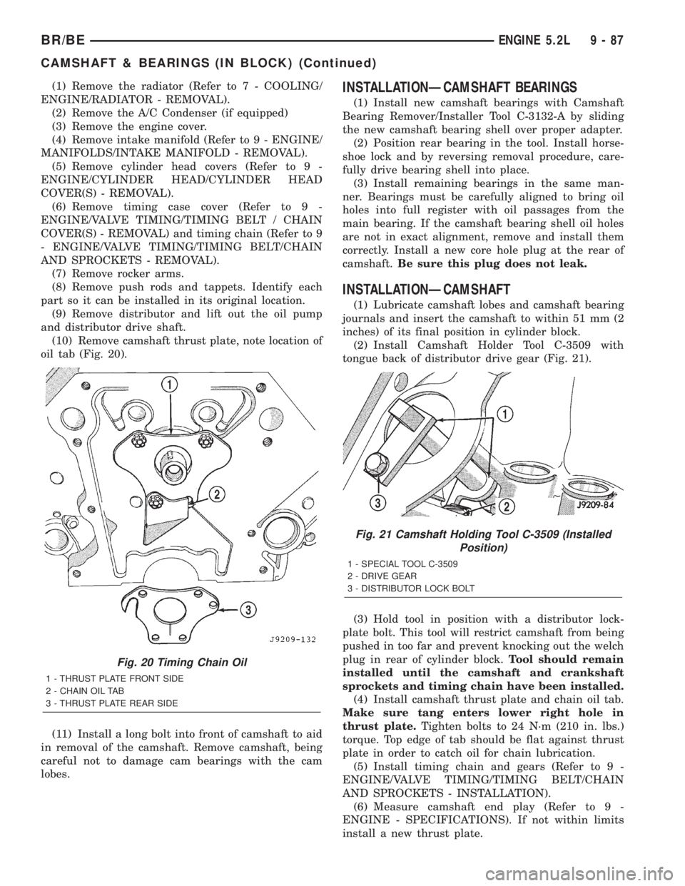
(10) Remove camshaft thrust plate, note location of
oil tab (Fig. 20).
(11) Install a long bolt into front of camshaft to aid
in removal of the camshaft. Remove camshaft, being
careful not to damage cam bearings with the cam
lobes.INSTALLATIONÐCAMSHAFT BEARINGS
(1) Install new camshaft bearings with Camshaft
Bearing Remover/Installer Tool C-3132-A by sliding
the new camshaft bearing shell over proper adapter.
(2) Position rear bearing in the tool. Install horse-
shoe lock and by reversing removal procedure, care-
fully drive bearing shell into place.
(3) Install remaining bearings in the same man-
ner. Bearings must be carefully aligned to bring oil
holes into full register with oil passages from the
main bearing. If the camshaft bearing shell oil holes
are not in exact alignment, remove and install them
correctly. Install a new core hole plug at the rear of
camshaft.Be sure this plug does not leak.
INSTALLATIONÐCAMSHAFT
(1) Lubricate camshaft lobes and camshaft bearing
journals and insert the camshaft to within 51 mm (2
inches) of its final position in cylinder block.
(2) Install Camshaft Holder Tool C-3509 with
tongue back of distributor drive gear (Fig. 21).
(3) Hold tool in position with a distributor lock-
plate bolt. This tool will restrict camshaft from being
pushed in too far and prevent knocking out the welch
plug in rear of cylinder block.Tool should remain
installed until the camshaft and crankshaft
sprockets and timing chain have been installed.
(4) Install camshaft thrust plate and chain oil tab.
Make sure tang enters lower right hole in
thrust plate.Tighten bolts to 24 N´m (210 in. lbs.)
torque. Top edge of tab should be flat against thrust
plate in order to catch oil for chain lubrication.
(5) Install timing chain and gears (Refer to 9 -
ENGINE/VALVE TIMING/TIMING BELT/CHAIN
AND SPROCKETS - INSTALLATION).
(6) Measure camshaft end play (Refer to 9 -
ENGINE - SPECIFICATIONS). If not within limits
install a new thrust plate.
Fig. 20 Timing Chain Oil
1 - THRUST PLATE FRONT SIDE
2 - CHAIN OIL TAB
3 - THRUST PLATE REAR SIDE
Fig. 21 Camshaft Holding Tool C-3509 (Installed
Position)
1 - SPECIAL TOOL C-3509
2 - DRIVE GEAR
3 - DISTRIBUTOR LOCK BOLT
BR/BEENGINE 5.2L 9 - 87
CAMSHAFT & BEARINGS (IN BLOCK) (Continued)
Page 1235 of 2889
(7) Each tappet reused must be installed in the
same position from which it was removed.When
camshaft is replaced, all of the tappets must be
replaced.
(8) Install distributor and distributor drive shaft.
(9) Install push rods and tappets.
(10) Install rocker arms.
(11) Install timing case cover (Refer to 9 -
ENGINE/VALVE TIMING/TIMING BELT / CHAIN
COVER(S) - INSTALLATION).
(12) Install cylinder head covers (Refer to 9 -
ENGINE/CYLINDER HEAD/CYLINDER HEAD
COVER(S) - INSTALLATION).
(13) Install intake manifold (Refer to 9 - ENGINE/
MANIFOLDS/INTAKE MANIFOLD - INSTALLA-
TION).
(14) Install the engine cover.
(15) Install the A/C Condenser (if equipped)
(16) Install the radiator (Refer to 7 - COOLING/
ENGINE/RADIATOR - INSTALLATION).
(17) Start engine check for leaks.
CONNECTING ROD BEARINGS
STANDARD PROCEDUREÐCONNECTING ROD
BEARING FITTING
Fit all rods on a bank until completed. DO NOT
alternate from one bank to another, because connect-
ing rods and pistons are not interchangeable from
one bank to another.
The bearing caps are not interchangeable and
should be marked at removal to ensure correct
assembly.
Each bearing cap has a small V-groove across the
parting face. When installing the lower bearing shell,
be certain that the V-groove in the shell is in line
with the V-groove in the cap. This provides lubrica-
tion of the cylinder wall in the opposite bank.
The bearing shells must be installed so that the
tangs are in the machined grooves in the rods and
caps.
Limits of taper or out-of-round on any crankshaft
journals should be held to 0.025 mm (0.001 in.).
Bearings are available in 0.025 mm (0.001 in.), 0.051
mm (0.002 in.), 0.076 mm (0.003 in.), 0.254 mm
(0.010 in.) and 0.305 mm (0.012 in.) undersize.
Install the bearings in pairs. DO NOT use a new
bearing half with an old bearing half. DO NOT
file the rods or bearing caps.
CRANKSHAFT
DESCRIPTION
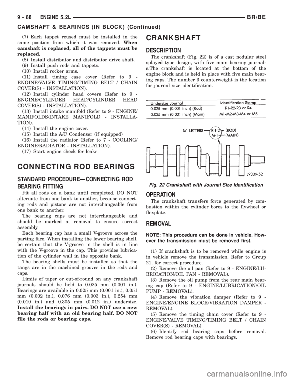
The crankshaft (Fig. 22) is of a cast nodular steel
splayed type design, with five main bearing journal-
s.The crankshaft is located at the bottom of the
engine block and is held in place with five main bear-
ing caps. The number 3 counterweight is the location
for journal size identification.
OPERATION
The crankshaft transfers force generated by com-
bustion within the cylinder bores to the flywheel or
flexplate.
REMOVAL
NOTE: This procedure can be done in vehicle. How-
ever the transmission must be removed first.
(1) If crankshaft is to be removed while engine is
in vehicle remove the transmission. Refer to Group
21, for correct procedure.
(2) Remove the oil pan (Refer to 9 - ENGINE/LU-
BRICATION/OIL PAN - REMOVAL).
(3) Remove the oil pump from the rear main bear-
ing cap (Refer to 9 - ENGINE/LUBRICATION/OIL
PUMP - REMOVAL).
(4) Remove the vibration damper (Refer to 9 -
ENGINE/ENGINE BLOCK/VIBRATION DAMPER -
REMOVAL).
(5) Remove the timing chain cover (Refer to 9 -
ENGINE/VALVE TIMING/TIMING BELT / CHAIN
COVER(S) - REMOVAL).
(6) Identify rod bearing caps before removal.
Remove rod bearing caps with bearings.
Fig. 22 Crankshaft with Journal Size Identification
9 - 88 ENGINE 5.2LBR/BE
CAMSHAFT & BEARINGS (IN BLOCK) (Continued)
Page 1236 of 2889
CAUTION: Support crankshaft before removing
main bearing caps. failure to do so will allow the
crankshaft to fall damaging the crankshaft.
(7) Using a suitable jack, support the crankshaft.
(8) Identify main bearing caps before removal.
Remove main bearing caps and bearings one at a
time.
(9) Lower the crankshaft out of the block.
(10) Remove and discard the crankshaft rear oil
seals.
(11) Remove and discard the front crankshaft oil
seal.
INSTALLATION
(1) Clean Gasket Maker residue and sealant from
the cylinder block and rear cap mating surface. Do
this before applying the MopartGasket Maker and
the installation of rear cap.
(2) Lightly oil the new upper seal lips with engine
oil.
(3) Install the new upper rear bearing oil seal with
the white paint facing towards the rear of the engine.
(4) Position the crankshaft into the cylinder block.
(5) Lightly oil the new lower seal lips with engine
oil.
(6) Install the new lower rear bearing oil seal into
the bearing cap with the white paint facing towards
the rear of the engine.
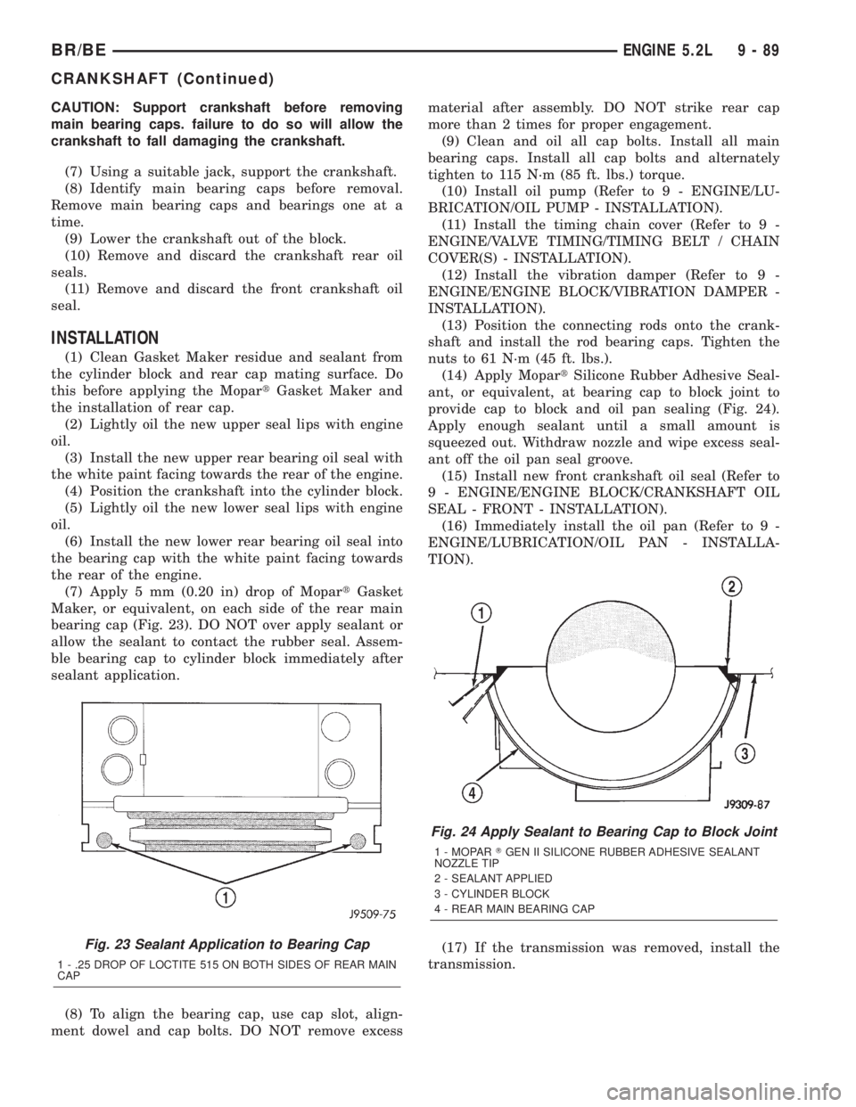
(7) Apply 5 mm (0.20 in) drop of MopartGasket
Maker, or equivalent, on each side of the rear main
bearing cap (Fig. 23). DO NOT over apply sealant or
allow the sealant to contact the rubber seal. Assem-
ble bearing cap to cylinder block immediately after
sealant application.
(8) To align the bearing cap, use cap slot, align-
ment dowel and cap bolts. DO NOT remove excessmaterial after assembly. DO NOT strike rear cap
more than 2 times for proper engagement.
(9) Clean and oil all cap bolts. Install all main
bearing caps. Install all cap bolts and alternately
tighten to 115 N´m (85 ft. lbs.) torque.
(10) Install oil pump (Refer to 9 - ENGINE/LU-
BRICATION/OIL PUMP - INSTALLATION).
(11) Install the timing chain cover (Refer to 9 -
ENGINE/VALVE TIMING/TIMING BELT / CHAIN
COVER(S) - INSTALLATION).
(12) Install the vibration damper (Refer to 9 -
ENGINE/ENGINE BLOCK/VIBRATION DAMPER -
INSTALLATION).
(13) Position the connecting rods onto the crank-
shaft and install the rod bearing caps. Tighten the
nuts to 61 N´m (45 ft. lbs.).
(14) Apply MopartSilicone Rubber Adhesive Seal-
ant, or equivalent, at bearing cap to block joint to
provide cap to block and oil pan sealing (Fig. 24).
Apply enough sealant until a small amount is
squeezed out. Withdraw nozzle and wipe excess seal-
ant off the oil pan seal groove.
(15) Install new front crankshaft oil seal (Refer to
9 - ENGINE/ENGINE BLOCK/CRANKSHAFT OIL
SEAL - FRONT - INSTALLATION).
(16) Immediately install the oil pan (Refer to 9 -
ENGINE/LUBRICATION/OIL PAN - INSTALLA-
TION).
(17) If the transmission was removed, install the
transmission.
Fig. 23 Sealant Application to Bearing Cap
1 - .25 DROP OF LOCTITE 515 ON BOTH SIDES OF REAR MAIN
CAP
Fig. 24 Apply Sealant to Bearing Cap to Block Joint
1 - MOPARTGEN II SILICONE RUBBER ADHESIVE SEALANT
NOZZLE TIP
2 - SEALANT APPLIED
3 - CYLINDER BLOCK
4 - REAR MAIN BEARING CAP
BR/BEENGINE 5.2L 9 - 89
CRANKSHAFT (Continued)
Page 1260 of 2889
Inspect mating surfaces of manifold for flatness
with a straight edge. Gasket surfaces must be flat
within 0.2 mm per 300 mm (0.008 inch per foot).
INSTALLATION
CAUTION: If the studs came out with the nuts when
removing the engine exhaust manifold, install new
studs. Apply sealer on the coarse thread ends.
Water leaks may develop at the studs if this precau-
tion is not taken.
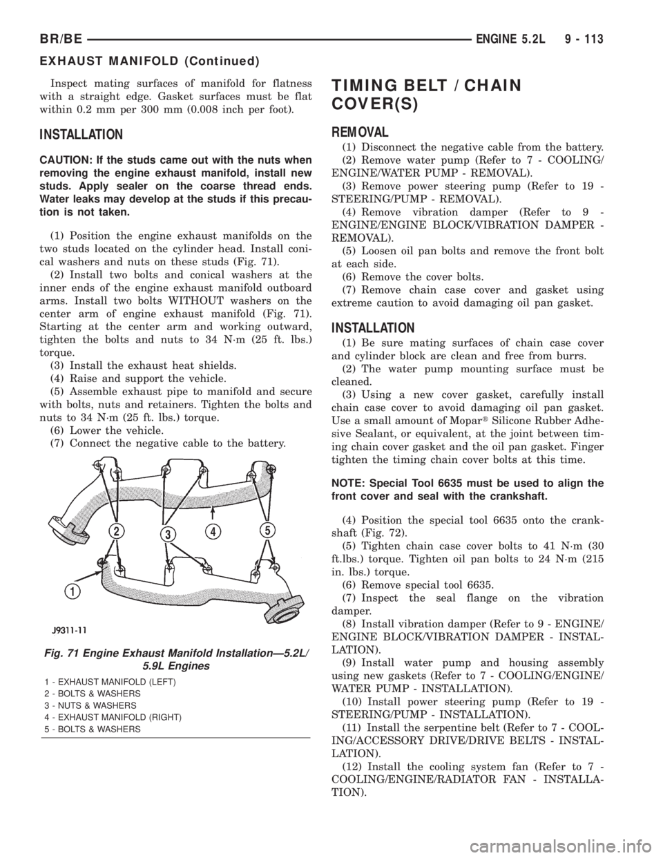
(1) Position the engine exhaust manifolds on the
two studs located on the cylinder head. Install coni-
cal washers and nuts on these studs (Fig. 71).
(2) Install two bolts and conical washers at the
inner ends of the engine exhaust manifold outboard
arms. Install two bolts WITHOUT washers on the
center arm of engine exhaust manifold (Fig. 71).
Starting at the center arm and working outward,
tighten the bolts and nuts to 34 N´m (25 ft. lbs.)
torque.
(3) Install the exhaust heat shields.
(4) Raise and support the vehicle.
(5) Assemble exhaust pipe to manifold and secure
with bolts, nuts and retainers. Tighten the bolts and
nuts to 34 N´m (25 ft. lbs.) torque.
(6) Lower the vehicle.
(7) Connect the negative cable to the battery.
TIMING BELT / CHAIN
COVER(S)
REMOVAL
(1) Disconnect the negative cable from the battery.
(2) Remove water pump (Refer to 7 - COOLING/
ENGINE/WATER PUMP - REMOVAL).
(3) Remove power steering pump (Refer to 19 -
STEERING/PUMP - REMOVAL).
(4) Remove vibration damper (Refer to 9 -
ENGINE/ENGINE BLOCK/VIBRATION DAMPER -
REMOVAL).
(5) Loosen oil pan bolts and remove the front bolt
at each side.
(6) Remove the cover bolts.
(7) Remove chain case cover and gasket using
extreme caution to avoid damaging oil pan gasket.
INSTALLATION
(1) Be sure mating surfaces of chain case cover
and cylinder block are clean and free from burrs.
(2) The water pump mounting surface must be
cleaned.
(3) Using a new cover gasket, carefully install
chain case cover to avoid damaging oil pan gasket.
Use a small amount of MopartSilicone Rubber Adhe-
sive Sealant, or equivalent, at the joint between tim-
ing chain cover gasket and the oil pan gasket. Finger
tighten the timing chain cover bolts at this time.
NOTE: Special Tool 6635 must be used to align the
front cover and seal with the crankshaft.
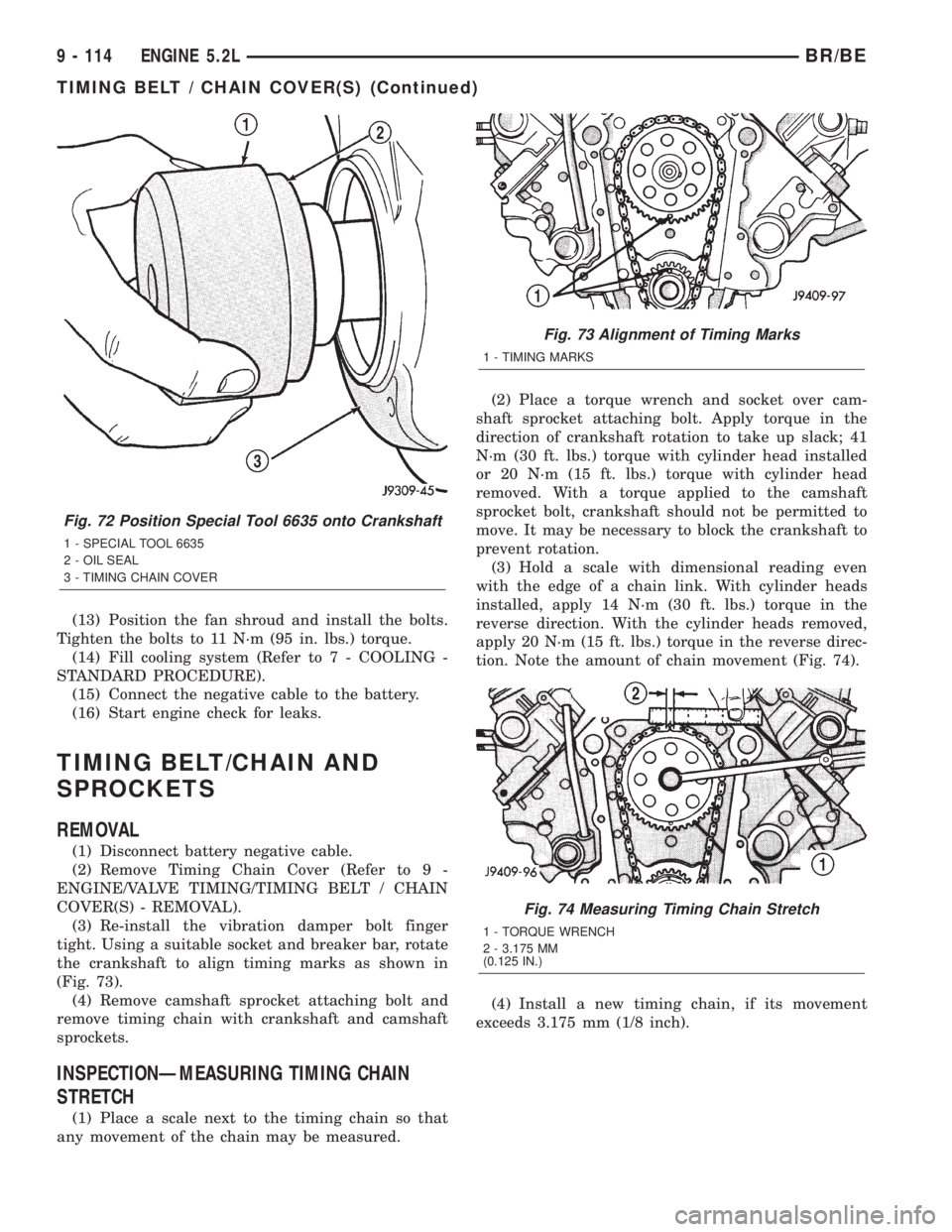
(4) Position the special tool 6635 onto the crank-
shaft (Fig. 72).
(5) Tighten chain case cover bolts to 41 N´m (30
ft.lbs.) torque. Tighten oil pan bolts to 24 N´m (215
in. lbs.) torque.
(6) Remove special tool 6635.
(7) Inspect the seal flange on the vibration
damper.
(8) Install vibration damper (Refer to 9 - ENGINE/
ENGINE BLOCK/VIBRATION DAMPER - INSTAL-
LATION).
(9) Install water pump and housing assembly
using new gaskets (Refer to 7 - COOLING/ENGINE/
WATER PUMP - INSTALLATION).
(10) Install power steering pump (Refer to 19 -
STEERING/PUMP - INSTALLATION).
(11) Install the serpentine belt (Refer to 7 - COOL-
ING/ACCESSORY DRIVE/DRIVE BELTS - INSTAL-
LATION).
(12) Install the cooling system fan (Refer to 7 -
COOLING/ENGINE/RADIATOR FAN - INSTALLA-
TION).
Fig. 71 Engine Exhaust Manifold InstallationÐ5.2L/
5.9L Engines
1 - EXHAUST MANIFOLD (LEFT)
2 - BOLTS & WASHERS
3 - NUTS & WASHERS
4 - EXHAUST MANIFOLD (RIGHT)
5 - BOLTS & WASHERS
BR/BEENGINE 5.2L 9 - 113
EXHAUST MANIFOLD (Continued)
Page 1261 of 2889
(13) Position the fan shroud and install the bolts.
Tighten the bolts to 11 N´m (95 in. lbs.) torque.
(14) Fill cooling system (Refer to 7 - COOLING -
STANDARD PROCEDURE).
(15) Connect the negative cable to the battery.
(16) Start engine check for leaks.
TIMING BELT/CHAIN AND
SPROCKETS
REMOVAL
(1) Disconnect battery negative cable.
(2) Remove Timing Chain Cover (Refer to 9 -
ENGINE/VALVE TIMING/TIMING BELT / CHAIN
COVER(S) - REMOVAL).
(3) Re-install the vibration damper bolt finger
tight. Using a suitable socket and breaker bar, rotate
the crankshaft to align timing marks as shown in
(Fig. 73).
(4) Remove camshaft sprocket attaching bolt and
remove timing chain with crankshaft and camshaft
sprockets.
INSPECTIONÐMEASURING TIMING CHAIN
STRETCH
(1) Place a scale next to the timing chain so that
any movement of the chain may be measured.(2) Place a torque wrench and socket over cam-
shaft sprocket attaching bolt. Apply torque in the
direction of crankshaft rotation to take up slack; 41
N´m (30 ft. lbs.) torque with cylinder head installed
or 20 N´m (15 ft. lbs.) torque with cylinder head
removed. With a torque applied to the camshaft
sprocket bolt, crankshaft should not be permitted to
move. It may be necessary to block the crankshaft to
prevent rotation.
(3) Hold a scale with dimensional reading even
with the edge of a chain link. With cylinder heads
installed, apply 14 N´m (30 ft. lbs.) torque in the
reverse direction. With the cylinder heads removed,
apply 20 N´m (15 ft. lbs.) torque in the reverse direc-
tion. Note the amount of chain movement (Fig. 74).
(4) Install a new timing chain, if its movement
exceeds 3.175 mm (1/8 inch).
Fig. 72 Position Special Tool 6635 onto Crankshaft
1 - SPECIAL TOOL 6635
2 - OIL SEAL
3 - TIMING CHAIN COVER
Fig. 73 Alignment of Timing Marks
1 - TIMING MARKS
Fig. 74 Measuring Timing Chain Stretch
1 - TORQUE WRENCH
2 - 3.175 MM
(0.125 IN.)
9 - 114 ENGINE 5.2LBR/BE
TIMING BELT / CHAIN COVER(S) (Continued)
Page 1262 of 2889
INSTALLATION
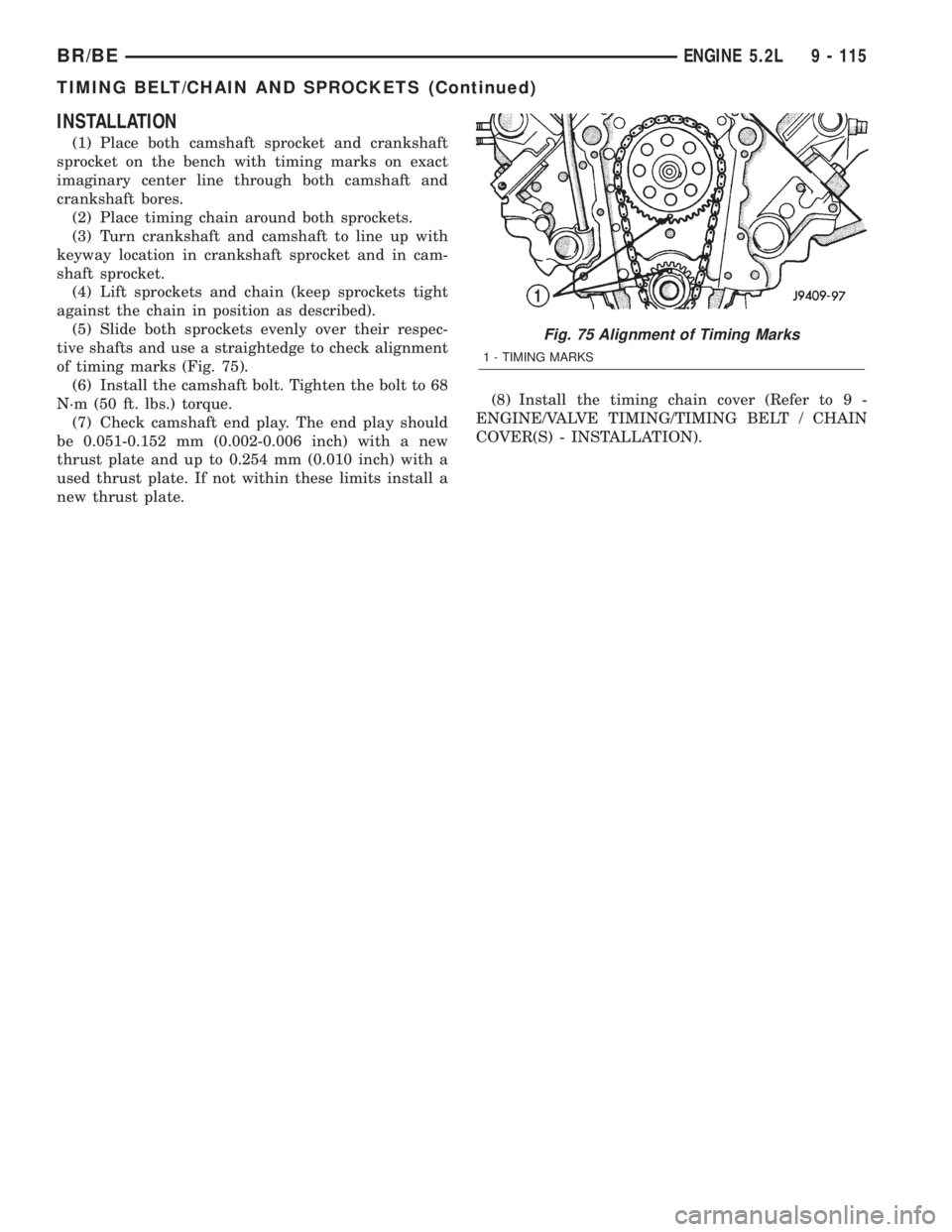
(1) Place both camshaft sprocket and crankshaft
sprocket on the bench with timing marks on exact
imaginary center line through both camshaft and
crankshaft bores.
(2) Place timing chain around both sprockets.
(3) Turn crankshaft and camshaft to line up with
keyway location in crankshaft sprocket and in cam-
shaft sprocket.
(4) Lift sprockets and chain (keep sprockets tight
against the chain in position as described).
(5) Slide both sprockets evenly over their respec-
tive shafts and use a straightedge to check alignment
of timing marks (Fig. 75).
(6) Install the camshaft bolt. Tighten the bolt to 68
N´m (50 ft. lbs.) torque.
(7) Check camshaft end play. The end play should
be 0.051-0.152 mm (0.002-0.006 inch) with a new
thrust plate and up to 0.254 mm (0.010 inch) with a
used thrust plate. If not within these limits install a
new thrust plate.(8) Install the timing chain cover (Refer to 9 -
ENGINE/VALVE TIMING/TIMING BELT / CHAIN
COVER(S) - INSTALLATION).
Fig. 75 Alignment of Timing Marks
1 - TIMING MARKS
BR/BEENGINE 5.2L 9 - 115
TIMING BELT/CHAIN AND SPROCKETS (Continued)
Page 1264 of 2889
FRONT MOUNT
REMOVAL.............................156
INSTALLATION..........................156
REAR MOUNT
REMOVAL.............................157
INSTALLATION..........................158
LUBRICATION
DESCRIPTION..........................158
OPERATION............................158
DIAGNOSIS AND TESTING................160
ENGINE OIL LEAKS....................160
ENGINE OIL PRESSURE................160
OIL
STANDARD PROCEDURE.................160
ENGINE OIL..........................160
OIL FILTER
REMOVAL.............................161
INSTALLATION..........................161
OIL PAN
REMOVAL.............................161
CLEANING.............................162
INSPECTION...........................162
INSTALLATION..........................162
OIL PUMP
REMOVAL.............................162
DISASSEMBLY..........................163INSPECTION...........................163
ASSEMBLY............................165
INSTALLATION..........................165
INTAKE MANIFOLD
DESCRIPTION..........................165
OPERATION............................165
DIAGNOSIS AND TESTING................165
INTAKE MANIFOLD LEAKAGE............165
REMOVAL.............................166
CLEANING.............................166
INSPECTION...........................166
INSTALLATION..........................166
EXHAUST MANIFOLD
DESCRIPTION..........................168
OPERATION............................168
REMOVAL.............................168
CLEANING.............................168
INSPECTION...........................168
INSTALLATION..........................168
TIMING BELT / CHAIN COVER(S)
REMOVAL.............................169
INSTALLATION..........................169
TIMING BELT/CHAIN AND SPROCKETS
REMOVAL.............................170
INSPECTION...........................170
INSTALLATION..........................170
ENGINE 5.9L
DESCRIPTION
The 5.9 Liter (360 CID) eight-cylinder engine is a
V-Type lightweight, single cam, overhead valve
engine with hydraulic roller tappets. This engine is
designed for unleaded fuel.
The engine lubrication system consists of a rotor
type oil pump and a full flow oil filter.
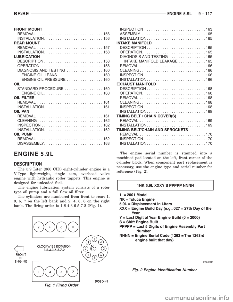
The cylinders are numbered from front to rear; 1,
3, 5, 7 on the left bank and 2, 4, 6, 8 on the right
bank. The firing order is 1-8-4-3-6-5-7-2 (Fig. 1).The engine serial number is stamped into a
machined pad located on the left, front corner of the
cylinder block. When component part replacement is
necessary, use the engine type and serial number for
reference (Fig. 2).
Fig. 1 Firing Order
Fig. 2 Engine Identification Number
BR/BEENGINE 5.9L 9 - 117