2001 DODGE RAM timing belt
[x] Cancel search: timing beltPage 1374 of 2889
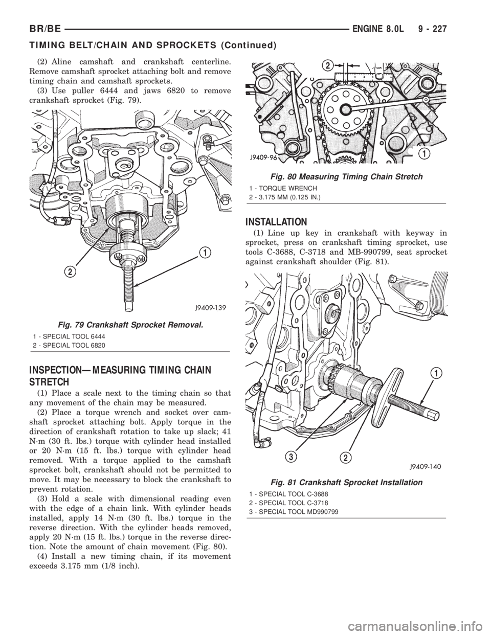
(2) Aline camshaft and crankshaft centerline.
Remove camshaft sprocket attaching bolt and remove
timing chain and camshaft sprockets.
(3) Use puller 6444 and jaws 6820 to remove
crankshaft sprocket (Fig. 79).
INSPECTIONÐMEASURING TIMING CHAIN
STRETCH
(1) Place a scale next to the timing chain so that
any movement of the chain may be measured.
(2) Place a torque wrench and socket over cam-
shaft sprocket attaching bolt. Apply torque in the
direction of crankshaft rotation to take up slack; 41
N´m (30 ft. lbs.) torque with cylinder head installed
or 20 N´m (15 ft. lbs.) torque with cylinder head
removed. With a torque applied to the camshaft
sprocket bolt, crankshaft should not be permitted to
move. It may be necessary to block the crankshaft to
prevent rotation.
(3) Hold a scale with dimensional reading even
with the edge of a chain link. With cylinder heads
installed, apply 14 N´m (30 ft. lbs.) torque in the
reverse direction. With the cylinder heads removed,
apply 20 N´m (15 ft. lbs.) torque in the reverse direc-
tion. Note the amount of chain movement (Fig. 80).
(4) Install a new timing chain, if its movement
exceeds 3.175 mm (1/8 inch).
INSTALLATION
(1) Line up key in crankshaft with keyway in
sprocket, press on crankshaft timing sprocket, use
tools C-3688, C-3718 and MB-990799, seat sprocket
against crankshaft shoulder (Fig. 81).
Fig. 79 Crankshaft Sprocket Removal.
1 - SPECIAL TOOL 6444
2 - SPECIAL TOOL 6820
Fig. 80 Measuring Timing Chain Stretch
1 - TORQUE WRENCH
2 - 3.175 MM (0.125 IN.)
Fig. 81 Crankshaft Sprocket Installation
1 - SPECIAL TOOL C-3688
2 - SPECIAL TOOL C-3718
3 - SPECIAL TOOL MD990799
BR/BEENGINE 8.0L 9 - 227
TIMING BELT/CHAIN AND SPROCKETS (Continued)
Page 1375 of 2889
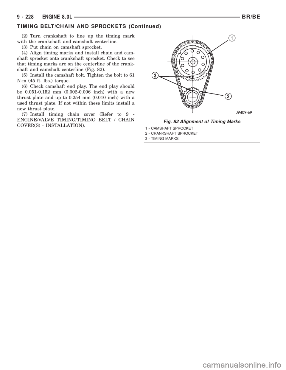
(2) Turn crankshaft to line up the timing mark
with the crankshaft and camshaft centerline.
(3) Put chain on camshaft sprocket.
(4) Align timing marks and install chain and cam-
shaft sprocket onto crankshaft sprocket. Check to see
that timing marks are on the centerline of the crank-
shaft and camshaft centerline (Fig. 82).
(5) Install the camshaft bolt. Tighten the bolt to 61
N´m (45 ft. lbs.) torque.
(6) Check camshaft end play. The end play should
be 0.051-0.152 mm (0.002-0.006 inch) with a new
thrust plate and up to 0.254 mm (0.010 inch) with a
used thrust plate. If not within these limits install a
new thrust plate.
(7) Install timing chain cover (Refer to 9 -
ENGINE/VALVE TIMING/TIMING BELT / CHAIN
COVER(S) - INSTALLATION).
Fig. 82 Alignment of Timing Marks
1 - CAMSHAFT SPROCKET
2 - CRANKSHAFT SPROCKET
3 - TIMING MARKS
9 - 228 ENGINE 8.0LBR/BE
TIMING BELT/CHAIN AND SPROCKETS (Continued)
Page 1380 of 2889
CONDITION POSSIBLE CAUSES CORRECTION
4. Oil cooler leak 4. Check and replace the oil cooler.
5. High blow-by forcing oil out the
breather.5. Check the breather tube area for signs of
oil loss. Perform the required repairs.
6. Turbocharger leaking oil to the air
intake.6. Inspect the air ducts for evidence of oil
transfer. Repair as required.
7. Piston rings not sealing (oil being
consumed by the engine).7. Perform blow-by check. Repair as
required.
COMPRESSION KNOCKS 1. Air in the fuel system. 1. Bleed the fuel system (Refer to 14 -
FUEL SYSTEM/FUEL DELIVERY -
STANDARD PROCEDURE).
2. Poor quality fuel or water/gasoline
contaminated fuel.2. Verify by operating from a temporary
tank with good fuel. Clean and flush the
fuel tank. Replace fuel/water separator filter.
3. Engine overloaded. 3. Verify the engine load rating is not being
exceeded.
4. Incorrect injection pump timing. 4. Check injection pump for proper
installation.
5. Improperly operating injectors. 5. Check and replace inoperative injectors.
EXCESSIVE VIBRATION 1. Loose or broken engine mounts. 1. Replace engine mounts.
2. Damaged fan or improperly
operating accessories.2. Check and replace the vibrating
components.
3. Improperly operating vibration
damper3. Inspect/replace vibration damper.
4. Improperly operating viscous fan
drive.4. Inspect/replace fan drive.
5. Worn or damaged generator
bearing.5. Check/replace generator.
6. Flywheel housing misaligned. 6. Check/correct flywheel alignment.
7. Loose or broken power
component.7. Inspect the crankshaft and rods for
damage that causes an unbalance
condition. Repair/replace as required.
8. Worn or unbalanced driveline
components.8. Check/repair driveline components.
EXCESSIVE ENGINE
NOISES1. Drive belt squeal, insufficient
tension or abnormally high loading.1. Check the automatic tensioner and
inspect the drive belt. Make sure water
pump, tensioner pulley, fan hub and
generator turn freely.
2. Intake air or exhaust leaks. 2. Refer to Excessive Exhaust Smoke
(Refer to 9 - ENGINE - DIAGNOSIS AND
TESTING).
3. Excessive valve lash. 3. Adjust valves. Make sure the push rods
are not bent and rocker arms, adjusting
screws, crossheads, are not severely worn.
Replace bent or severely worn components.
BR/BEENGINE 5.9L DIESEL 9 - 233
ENGINE 5.9L DIESEL (Continued)
Page 1405 of 2889
(6) If adjustment/resetting is required, loosen the
lock nut on rocker arms and turn the adjusting screw
until the desired lash is obtained:
²INTAKE0.254 mm (0.010 in.)
²EXHAUST0.508 mm (0.020 in.)Tighten the lock
nut and re-check the valve lash.
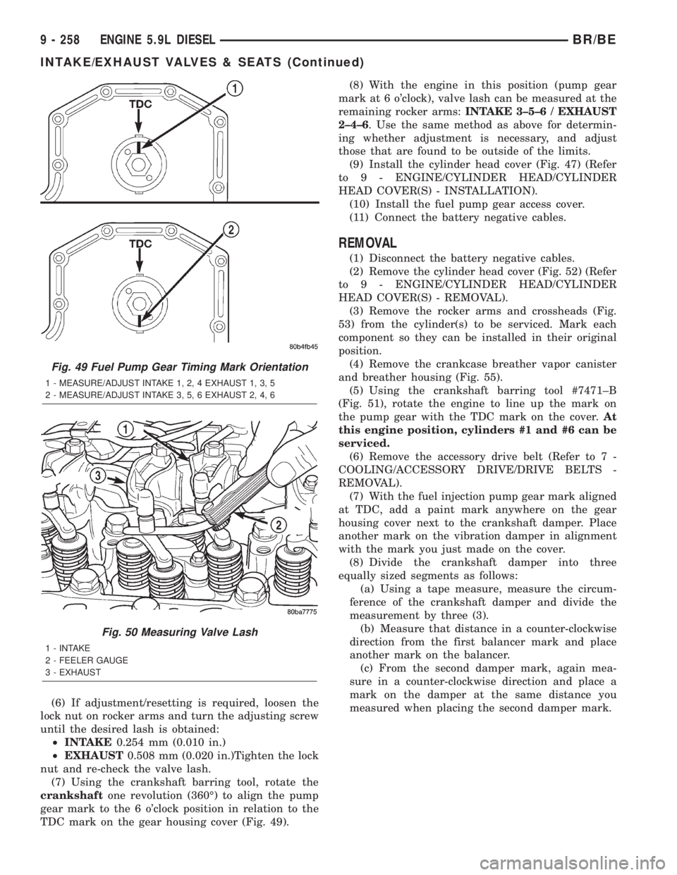
(7) Using the crankshaft barring tool, rotate the
crankshaftone revolution (360É) to align the pump
gear mark to the 6 o'clock position in relation to the
TDC mark on the gear housing cover (Fig. 49).(8) With the engine in this position (pump gear
mark at 6 o'clock), valve lash can be measured at the
remaining rocker arms:INTAKE 3±5±6 / EXHAUST
2±4±6. Use the same method as above for determin-
ing whether adjustment is necessary, and adjust
those that are found to be outside of the limits.
(9) Install the cylinder head cover (Fig. 47) (Refer
to 9 - ENGINE/CYLINDER HEAD/CYLINDER
HEAD COVER(S) - INSTALLATION).
(10) Install the fuel pump gear access cover.
(11) Connect the battery negative cables.
REMOVAL
(1) Disconnect the battery negative cables.
(2) Remove the cylinder head cover (Fig. 52) (Refer
to 9 - ENGINE/CYLINDER HEAD/CYLINDER
HEAD COVER(S) - REMOVAL).
(3) Remove the rocker arms and crossheads (Fig.
53) from the cylinder(s) to be serviced. Mark each
component so they can be installed in their original
position.
(4) Remove the crankcase breather vapor canister
and breather housing (Fig. 55).
(5) Using the crankshaft barring tool #7471±B
(Fig. 51), rotate the engine to line up the mark on
the pump gear with the TDC mark on the cover.At
this engine position, cylinders #1 and #6 can be
serviced.
(6) Remove the accessory drive belt (Refer to 7 -
COOLING/ACCESSORY DRIVE/DRIVE BELTS -
REMOVAL).
(7) With the fuel injection pump gear mark aligned
at TDC, add a paint mark anywhere on the gear
housing cover next to the crankshaft damper. Place
another mark on the vibration damper in alignment
with the mark you just made on the cover.
(8) Divide the crankshaft damper into three
equally sized segments as follows:
(a) Using a tape measure, measure the circum-
ference of the crankshaft damper and divide the
measurement by three (3).
(b) Measure that distance in a counter-clockwise
direction from the first balancer mark and place
another mark on the balancer.
(c) From the second damper mark, again mea-
sure in a counter-clockwise direction and place a
mark on the damper at the same distance you
measured when placing the second damper mark.
Fig. 49 Fuel Pump Gear Timing Mark Orientation
1 - MEASURE/ADJUST INTAKE 1, 2, 4 EXHAUST 1, 3, 5
2 - MEASURE/ADJUST INTAKE 3, 5, 6 EXHAUST 2, 4, 6
Fig. 50 Measuring Valve Lash
1 - INTAKE
2 - FEELER GAUGE
3 - EXHAUST
9 - 258 ENGINE 5.9L DIESELBR/BE
INTAKE/EXHAUST VALVES & SEATS (Continued)
Page 1421 of 2889
(10)Verify valve lash adjustment (Refer to 9 -
ENGINE/CYLINDER HEAD/INTAKE/EXHAUST
VALVES & SEATS - STANDARD PROCEDURE).
(11)
Install the cylinder head cover and reusable gas-
ket (Fig. 85) (Refer to 9 - ENGINE/CYLINDER HEAD/
CYLINDER HEAD COVER(S) - INSTALLATION).
(12) Install gear housing cover (Refer to 9 -
ENGINE/VALVE TIMING/GEAR HOUSING COVER
- INSTALLATION).
(13) Install the crankshaft damper (Fig. 83) (Refer
to 9 - ENGINE/ENGINE BLOCK/VIBRATION
DAMPER - INSTALLATION).
(14) Install the fan support/hub assembly (Fig. 82)
and tighten bolts to 24 N´m (18 ft. lbs.) torque.
(15) Install the crankcase breather housing (Refer
to 9 - ENGINE - INSTALLATION).
(16) Install the charge air cooler (with a/c con-
denser and auxiliary transmission oil cooler, if
equipped) and tighten the mounting bolts to 2 N´m
(17 in. lbs.) torque.
(17) Connect charge air cooler inlet and outlet
pipes. Tighten clamps to 10 N´m (100 in. lbs.) torque.
(18) Install the radiator upper support panel.
(19) Close radiator petcock and lower the radiator
into the engine compartment. Tighten the mounting
bolts to 11 N´m (95 in. lbs.) torque.
(20) Raise vehicle on hoist.
(21)
Connect radiator lower hose and install clamp.
(22) Connect transmission auxiliary oil cooler lines
(if equipped).
(23) Lower vehicle.
(24) Install the fan shroud and tighten the mount-
ing screws to 6 N´m (50 in. lbs.) torque.(25) Install the viscous fan/drive assembly (Refer
to 7 - COOLING/ENGINE/RADIATOR FAN -
INSTALLATION).
(26) Install the coolant recovery and windshield
washer fluid reservoirs to the fan shroud.
(27) Connect the coolant recovery hose to the radi-
ator filler neck.
(28) Install the accessory drive belt (Refer to 7 -
COOLING/ACCESSORY DRIVE/DRIVE BELTS -
INSTALLATION).
(29) Install the front bumper assembly (Refer to 13
- FRAMES & BUMPERS/BUMPERS/FRONT
BUMPER - INSTALLATION).
(30) Add engine coolant (Refer to 7 - COOLING -
STANDARD PROCEDURE).
(31) Charge A/C system with refrigerant (if A/C
equipped) (Refer to 24 - HEATING & AIR CONDI-
TIONING/PLUMBING - STANDARD PROCEDURE).
(32) Connect the battery negative cables.
(33) Start engine and check for engine oil and cool-
ant leaks.
CONNECTING ROD BEARINGS
STANDARD PROCEDUREÐCONNECTING ROD
BEARING AND CRANKSHAFT JOURNAL
CLEARANCE
Measure the connecting rod bore with the bearings
installed and the bolts tightened to 100 N´m (73 ft.
lbs.) torque.
Record the smaller diameter.
Measure the diameter of the rod journal at the
location shown (Fig. 99). Calculate the average diam-
eter for each side of the journal.
The clearance is the difference between the con-
necting rod bore (smallest diameter) and the average
diameter for each side of the crankshaft journal.
CONNECTING ROD JOURNAL DIAMETER
LIMITS CHART
DESCRIPTION MEASUREMENT
CRANKSHAFT ROD
JOURNAL DIAMETERMINIMUM 68.962 mm
(2.715 in.)
MAXIMUM 69.013 mm
(2.717 in.)
OUT-OF-ROUND MAXIMUM 0.050 mm
(0.002 in.)
TAPER MAXIMUM 0.013 mm
(0.0005 in.)
BEARING CLEARANCE MAXIMUM 0.089 mm
(0.0035 in.)
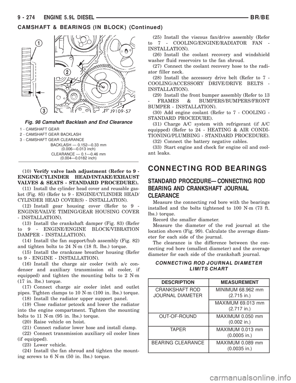
Fig. 98 Camshaft Backlash and End Clearance
1 - CAMSHAFT GEAR
2 - CAMSHAFT GEAR BACKLASH
3 - CAMSHAFT GEAR CLEARANCE
BACKLASH Ð 0.152Ð0.33 mm
(0.006Ð0.013 inch)
CLEARANCE Ð 0.1Ð0.46 mm
(0.004Ð0.0182 inch)
9 - 274 ENGINE 5.9L DIESELBR/BE
CAMSHAFT & BEARINGS (IN BLOCK) (Continued)
Page 1446 of 2889
INSTALLATION
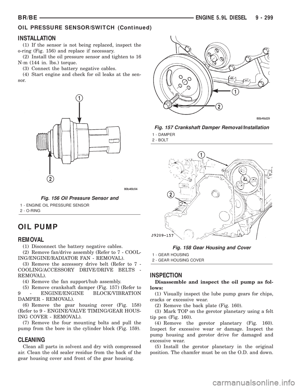
(1) If the sensor is not being replaced, inspect the
o-ring (Fig. 156) and replace if necessary.
(2) Install the oil pressure sensor and tighten to 16
N´m (144 in. lbs.) torque.
(3) Connect the battery negative cables.
(4) Start engine and check for oil leaks at the sen-
sor.
OIL PUMP
REMOVAL
(1) Disconnect the battery negative cables.
(2) Remove fan/drive assembly (Refer to 7 - COOL-
ING/ENGINE/RADIATOR FAN - REMOVAL).
(3) Remove the accessory drive belt (Refer to 7 -
COOLING/ACCESSORY DRIVE/DRIVE BELTS -
REMOVAL).
(4) Remove the fan support/hub assembly.
(5) Remove crankshaft damper (Fig. 157) (Refer to
9 - ENGINE/ENGINE BLOCK/VIBRATION
DAMPER - REMOVAL).
(6) Remove the gear housing cover (Fig. 158)
(Refer to 9 - ENGINE/VALVE TIMING/GEAR HOUS-
ING COVER - REMOVAL).
(7) Remove the four mounting bolts and pull the
pump from the bore in the cylinder block (Fig. 159).
CLEANING
Clean all parts in solvent and dry with compressed
air. Clean the old sealer residue from the back of the
gear housing cover and front of the gear housing.
INSPECTION
Disassemble and inspect the oil pump as fol-
lows:
(1) Visually inspect the lube pump gears for chips,
cracks or excessive wear.
(2) Remove the back plate (Fig. 160).
(3) Mark TOP on the gerotor planetary using a felt
tip pen (Fig. 160).
(4) Remove the gerotor planetary (Fig. 160).
Inspect for excessive wear or damage. Inspect the
pump housing and gerotor drive for damaged and
excessive wear.
(5) Install the gerotor planetary in the original
position. The chamfer must be on the O.D. and down.
Fig. 156 Oil Pressure Sensor and
1 - ENGINE OIL PRESSURE SENSOR
2 - O-RING
Fig. 157 Crankshaft Damper Removal/Installation
1 - DAMPER
2 - BOLT
Fig. 158 Gear Housing and Cover
1 - GEAR HOUSING
2 - GEAR HOUSING COVER
BR/BEENGINE 5.9L DIESEL 9 - 299
OIL PRESSURE SENSOR/SWITCH (Continued)
Page 1448 of 2889
(7) Apply a bead of MopartSilicone Rubber Adhe-
sive Sealant or equivalent to the gear housing cover
sealing surface.(8) Install the gear housing cover (Refer to 9 -
ENGINE/VALVE TIMING/GEAR HOUSING COVER
- INSTALLATION).
(9) Install the vibration damper (Refer to 9 -
ENGINE/ENGINE BLOCK/VIBRATION DAMPER -
INSTALLATION).
(10) Install the fan support/hub assembly and
torque bolts to 24 N´m (18 ft. lbs.).
(11) Install the accessory drive belt (Refer to 7 -
COOLING/ACCESSORY DRIVE/DRIVE BELTS -
INSTALLATION).
(12) Install the cooling fan (Refer to 7 - COOLING/
ENGINE/RADIATOR FAN - INSTALLATION).
(13) Connect battery negative cables.
(14) Start engine and check for oil leaks.
INTAKE MANIFOLD
REMOVAL
(1) Disconnect the battery negative cables.
(2) Remove the charge air cooler outlet tube from
the air inlet housing (Fig. 167).
(3) Remove the engine oil dipstick tube mounting
bolt (Fig. 167). Position dipstick tube to the side.
(4) Disconnect the air grid heater power cables at
the cable mounting studs (Fig. 168).
(5) Remove the four (4) air inlet housing mounting
bolts (Fig. 168) and remove the housing from top of
the heater elements.
(6) Remove the intake air grid heater from the
manifold (Fig. 169).
(7) Remove the high pressure fuel lines.(Refer to
14 - FUEL SYSTEM/FUEL DELIVERY/FUEL LINES
- REMOVAL).
(8) Remove the remaining intake manifold cover-
to-cylinder head bolts.
(9) Remove the intake manifold cover and gasket.
Keep the gasket material and any other material out
of the air intake.
(10) Clean the intake manifold cover and cylinder
head sealing surface.
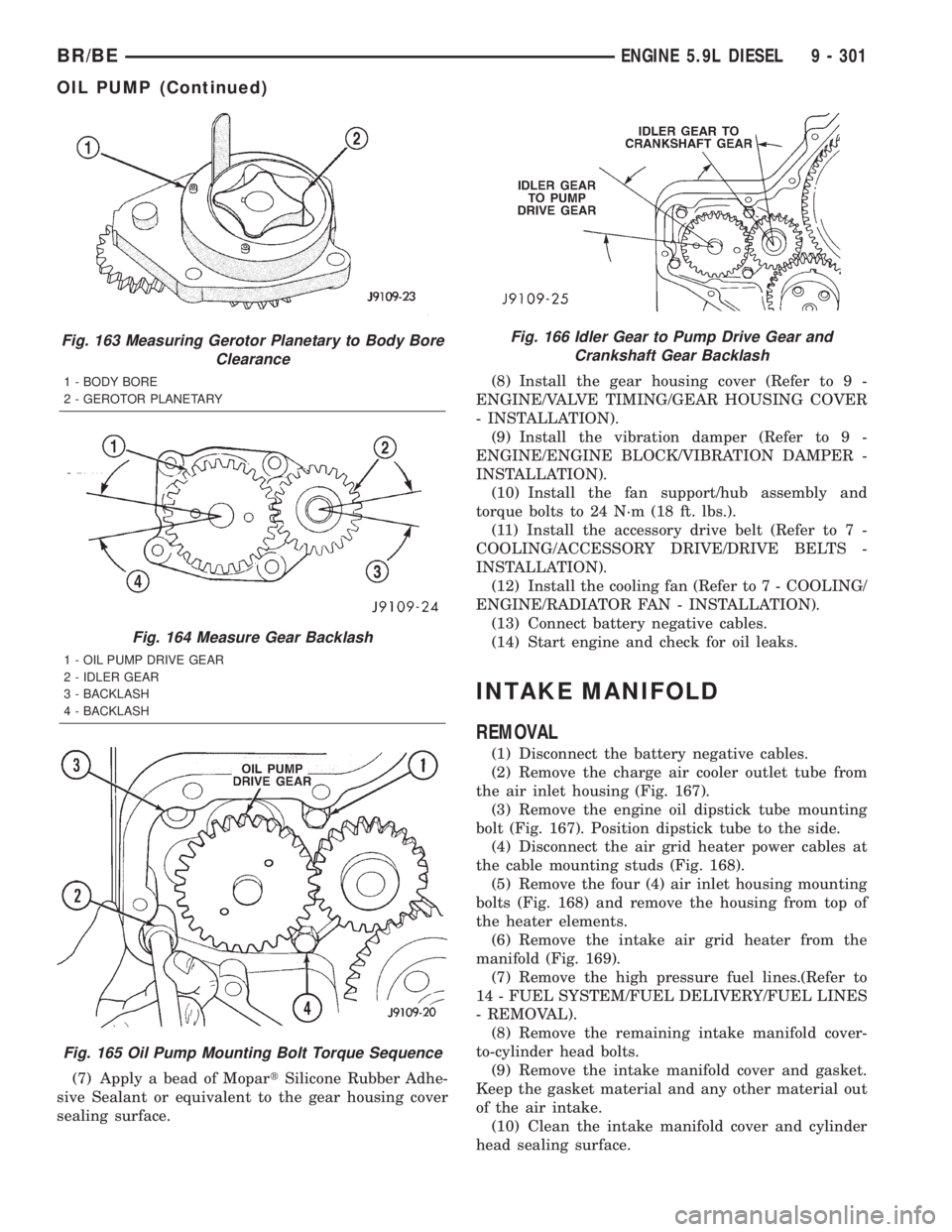
Fig. 163 Measuring Gerotor Planetary to Body Bore
Clearance
1 - BODY BORE
2 - GEROTOR PLANETARY
Fig. 164 Measure Gear Backlash
1 - OIL PUMP DRIVE GEAR
2 - IDLER GEAR
3 - BACKLASH
4 - BACKLASH
Fig. 165 Oil Pump Mounting Bolt Torque Sequence
Fig. 166 Idler Gear to Pump Drive Gear and
Crankshaft Gear Backlash
BR/BEENGINE 5.9L DIESEL 9 - 301
OIL PUMP (Continued)
Page 2798 of 2889
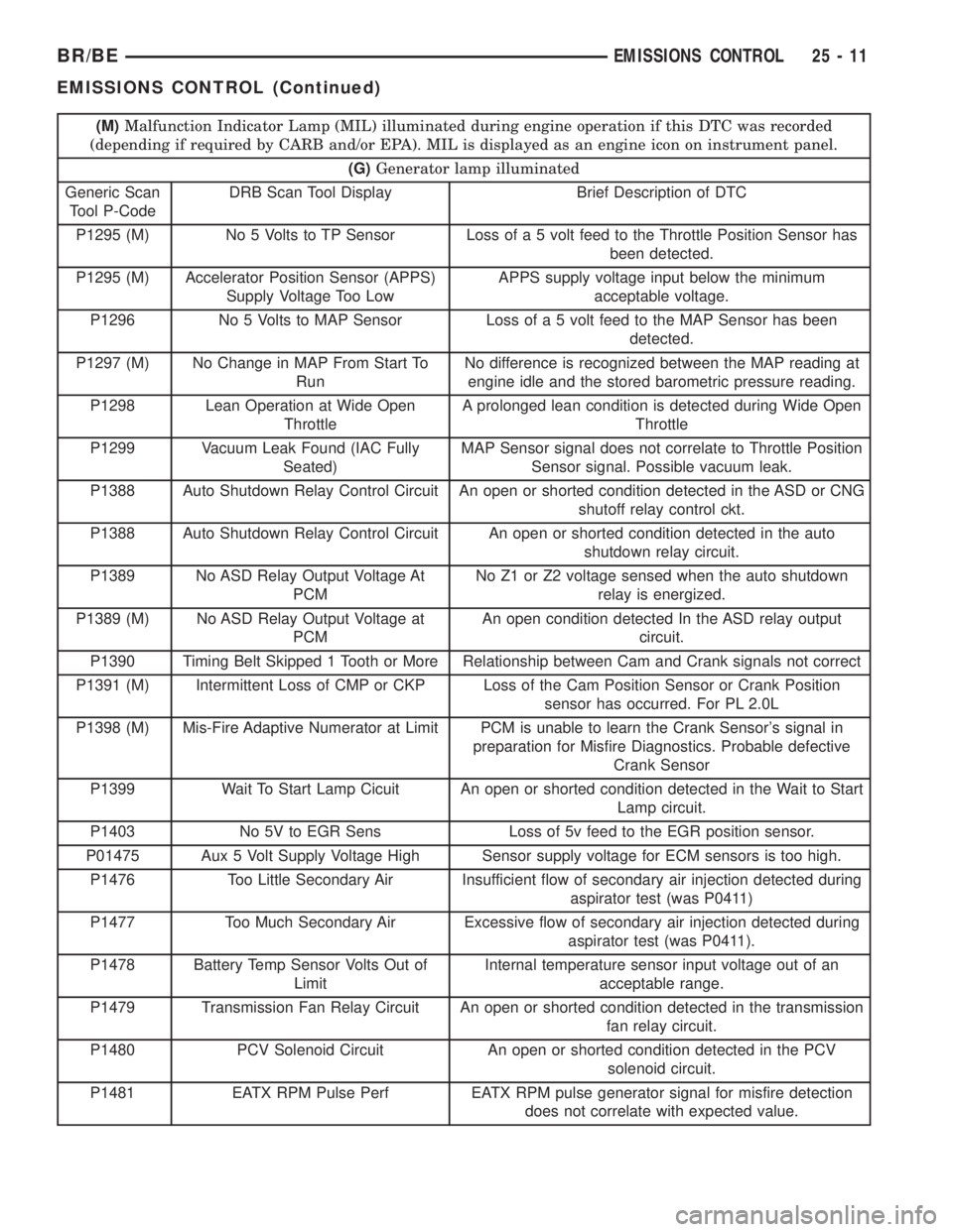
(M)Malfunction Indicator Lamp (MIL) illuminated during engine operation if this DTC was recorded
(depending if required by CARB and/or EPA). MIL is displayed as an engine icon on instrument panel.
(G)Generator lamp illuminated
Generic Scan
Tool P-CodeDRB Scan Tool Display Brief Description of DTC
P1295 (M) No 5 Volts to TP Sensor Loss of a 5 volt feed to the Throttle Position Sensor has
been detected.
P1295 (M) Accelerator Position Sensor (APPS)
Supply Voltage Too LowAPPS supply voltage input below the minimum
acceptable voltage.
P1296 No 5 Volts to MAP Sensor Loss of a 5 volt feed to the MAP Sensor has been
detected.
P1297 (M) No Change in MAP From Start To
RunNo difference is recognized between the MAP reading at
engine idle and the stored barometric pressure reading.
P1298 Lean Operation at Wide Open
ThrottleA prolonged lean condition is detected during Wide Open
Throttle
P1299 Vacuum Leak Found (IAC Fully
Seated)MAP Sensor signal does not correlate to Throttle Position
Sensor signal. Possible vacuum leak.
P1388 Auto Shutdown Relay Control Circuit An open or shorted condition detected in the ASD or CNG
shutoff relay control ckt.
P1388 Auto Shutdown Relay Control Circuit An open or shorted condition detected in the auto
shutdown relay circuit.
P1389 No ASD Relay Output Voltage At
PCMNo Z1 or Z2 voltage sensed when the auto shutdown
relay is energized.
P1389 (M) No ASD Relay Output Voltage at
PCMAn open condition detected In the ASD relay output
circuit.
P1390 Timing Belt Skipped 1 Tooth or More Relationship between Cam and Crank signals not correct
P1391 (M) Intermittent Loss of CMP or CKP Loss of the Cam Position Sensor or Crank Position
sensor has occurred. For PL 2.0L
P1398 (M) Mis-Fire Adaptive Numerator at Limit PCM is unable to learn the Crank Sensor's signal in
preparation for Misfire Diagnostics. Probable defective
Crank Sensor
P1399 Wait To Start Lamp Cicuit An open or shorted condition detected in the Wait to Start
Lamp circuit.
P1403 No 5V to EGR Sens Loss of 5v feed to the EGR position sensor.
P01475 Aux 5 Volt Supply Voltage High Sensor supply voltage for ECM sensors is too high.
P1476 Too Little Secondary Air Insufficient flow of secondary air injection detected during
aspirator test (was P0411)
P1477 Too Much Secondary Air Excessive flow of secondary air injection detected during
aspirator test (was P0411).
P1478 Battery Temp Sensor Volts Out of
LimitInternal temperature sensor input voltage out of an
acceptable range.
P1479 Transmission Fan Relay Circuit An open or shorted condition detected in the transmission
fan relay circuit.
P1480 PCV Solenoid Circuit An open or shorted condition detected in the PCV
solenoid circuit.
P1481 EATX RPM Pulse Perf EATX RPM pulse generator signal for misfire detection
does not correlate with expected value.
BR/BEEMISSIONS CONTROL 25 - 11
EMISSIONS CONTROL (Continued)